

Page 1

Jetstream
Garage Fan
See page 2
ENGLISH
Vea la página 13
ESPAÑOL
Model 9020X
READ AND SAVE THESE INSTRUCTIONS
www.hunterfan.com
42727-01
04/25/2007
Page 2
Table of Contents
Safety Instructions .......................................................... 2
Garage Fan Components ................................................... 4
Site Selection & Preparation ............................................. 4
Installation & Operation ................................................... 5
Ceiling Mount ............................................................... 5
Horizontal Surface Use .................................................. 9
Maintenance .................................................................... 9
Troubleshooting
Problems and Solutions ................................................10
SAFETY INSTRUCTIONS
When using electrical appliances, basic precautions should always be
Read & Save These Instructions
taken to reduce the risk of re, electric shock and personal injury.
WARNING - To reduce the risk of re or electrical shock, DO NOT
use this fan with any solid-state speed control device.
1. Read all instructions before using this fan.
2. Improper assembly may result in the risk of re, electric shock or
personal injury.
3. To prevent the risk of re and electric shock, DO NOT use the unit
near windows. Rain and moisture may create an electrical hazard.
4. The power plug must be removed from the power socket when not
in use, before cleaning, servicing, maintenance and before moving
to another location.
5. DO NOT put fan in a damp place or where humidity is high—such as
a bathroom.
6. When used on the oor or on a table, place the fan on a at, dry,
stable surface to avoid tipping over.
7. Use fan only for intended use, as described in this instruction manual.
8. To protect against electrical shock, DO NOT immerse unit, plug, or
cord in water or spray with liquids.
9. NEVER insert ngers, pencils or any other objects through the grille.
42727-01
Continued
2
Page 3

SAFETY INSTRUCTIONS Continued
10. DO NOT operate this fan:
• if the cord is damaged
• if the fan malfunctions
• if the fan has been dropped or damaged in any way
11. To disconnect, grip plug and pull from wall outlet. NEVER yank on
the cord.
12. This product is intended for household use only and not for commercial or industrial use.
13. DO NOT operate fan in the presence of explosive and/or ammable
fumes.
14. DO NOT place fan or any parts near an open ame, cooking or any
other heating appliances.
15. DO NOT use near curtains, plants, window treatments, etc.
16. Never operate the fan if the grills are not properly installed. Operating the fan without the grills could result in serious injury.
17. The appliance is not intended for use by young children or inrm
persons without supervision. Young children should be supervised to
ensure that they do not play with the appliance.
18. This appliance has a grounded three-prong plug and is suitable for
grounded receptacle use only. An adapter is available for connecting
three-blade grounding-type plugs to two-slot receptacles. The
adapter must be properly grounded. DO NOT attempt to defeat the
purpose of this safely feature.
3
42727-01
Page 4

Garage Fan Components
Stationary Leg
Split Sleeve
Adjustable Leg
Split Sleeve
Adjustable
Leg
Leg Adjust
Lever
Site Selection & Preparation
Downrod
Stationary
Leg
Speed Control
Switch
Downrod Cup
Snake Lamp
(Available on
select models)
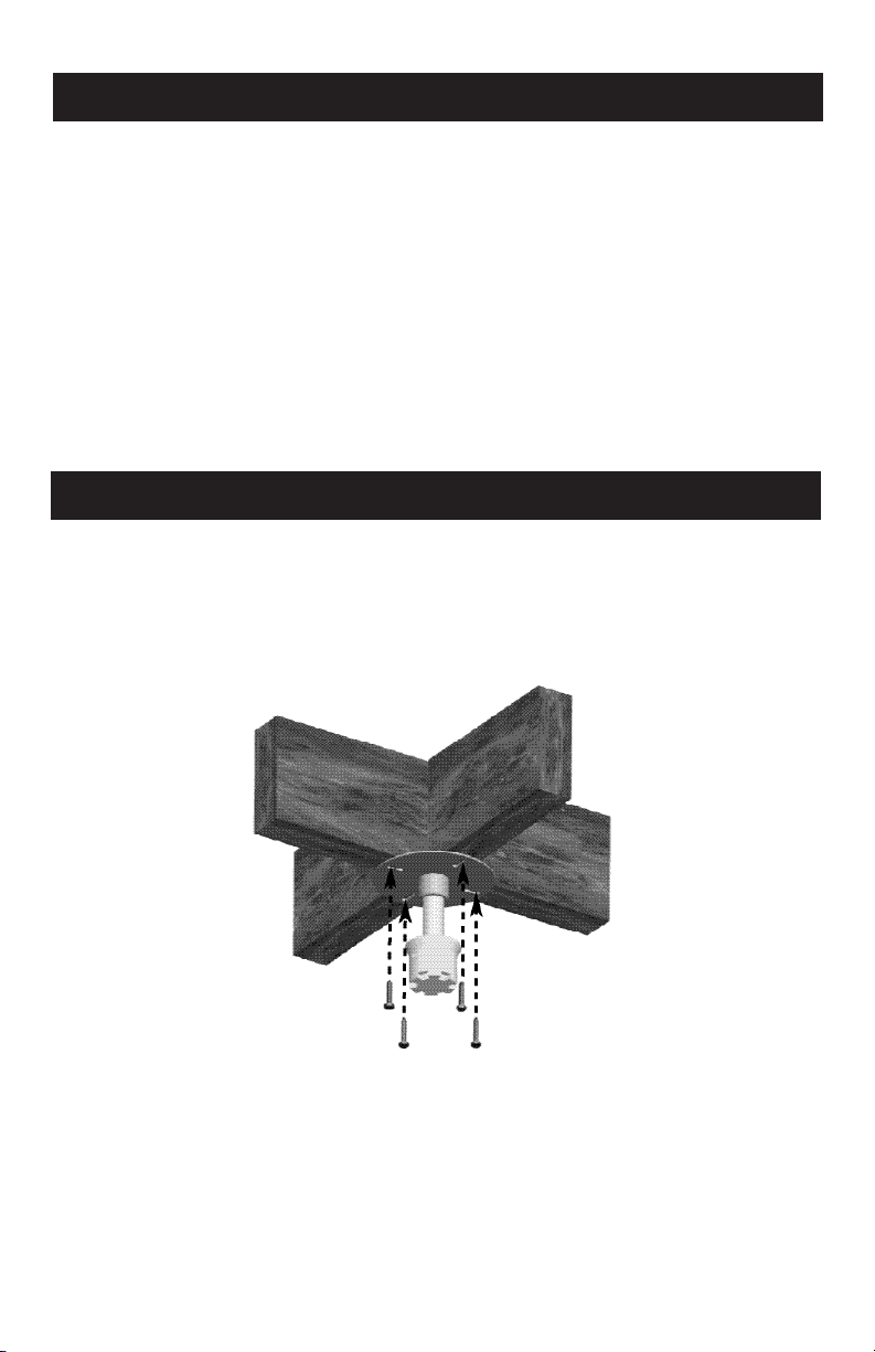
NOTE: Your Garage Fan is intended for mounting at the intersec-
tion of a joist and two braces. See Figure 1. If the location you’ve
selected does not have such a conguration, then securely install
two pieces of framing material between the joists to form the
intesection.
NOTE: Electrical work and electrical wiring must be done by a
qualied electrician, and must be in compliance with all applicable codes and standards, including re-rated construction codes
and standards.
1. Select the location on the ceiling from which you wish to hang
your Garage Fan. Ensure the location you’ve selected has 120V
60 Hz power available within the reach of your Garage Fan’s 6’
Power Cord, such as the outlet on most garage door openers. If
no power outlet is available within the reach of your Garage Fan’s
Power Cord, then run the proper cabling and an outlet to within
reach of your Garage Fan’s Power Cord.
2. Select a location on the ceiling that will not interfere with the
opening and closing of the garage door.
42727-01
4
Continued
Page 5
Site Selection and Preparation
3. Hang your Garage Fan from a location such that people can
not bump their heads against the fan.
4. Hang your Garage Fan at a height that will allow you to 1)
easily remove it from the Downrod Assembly for Horizontal
Surface use, and 2) easily reach the Snake Lamp (available
on select models). Longer Downrods can be purchased by
calling Hunter Fan Customer Service at 1-888-830-1326.
5. Remove your Garage Fan from its box, and remove all plastic
wrapping and packing materials from the fan.
Continued
Installation & Operation
Ceiling Mount
1. Use the four provided Mounting Screws to secure the Mounting
Flange/Downrod Assembly to two intersecting joists. Refer to
Site Selection & Preparation, pg. 4. See Figure 1.
Figure 1
5
NOTE: For clarity, ceiling
drywall or sheetrock has
been omitted.
42727-01
Page 6
Installation & Operation
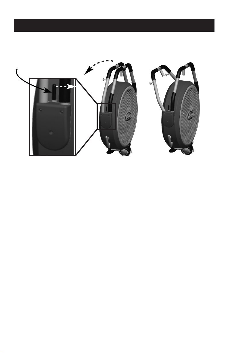
2. Move the Leg Adjust Lever toward the front of the fan, then tilt
back the Adjustable Leg. See Figure 2.
Leg Adjust
Lever
Figure 2
3. Push the entire Adjustable Leg/Stationary Leg Assembly back so
the Stationary Split Sleeve clears the top of the fan.
42727-01
6
Page 7
Installation & Operation
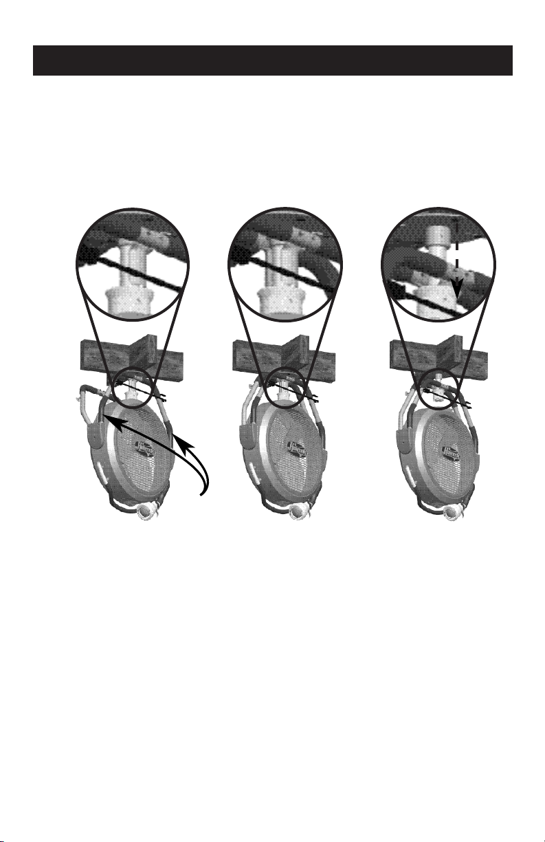
4. Grasp the Stationary Leg and position the Stationary Leg Split
Sleeve onto the Downrod, over the Downrod Cup. See Figure 3a.
While maintaining your grasp on the Stationary Leg, bring the Ad-
justable Leg forward, positioning the Adjustable Leg Split Sleeve
around the Downrod Cup. See Figure 3b. Lower the Split Sleeve
into the Downrod Cup. See Figure 3c
Stationary
Leg
Figure 3a
5. FOR MODELS WITH THE SNAKE LAMP - Open the Snake Lamp
Cage. Install an R20 50W max. light bulb (not supplied). NOTE:
Use ONLY an R20 50W max. light bulb in your Garage Fan Snake
Lamp. Shut the Snake Lamp Cage.
6. Plug your fan’s Power Cord into a 120V 60Hz outlet.
Figure 3b
7
Figure 3c
42727-01
Page 8

Installation & Operation
7. Use the Speed Control Knob to select your fan’s speed. See Figure
4.
Medium
Low
Off
Figure 4
8. While your Garage Fan is mounted to the ceiling, you can turn it
and tilt it to direct the airow. To turn the fan, raise the fan so the
Split Sleeve clears the Downrod Cup, turn the fan to your desired
position, and lower the fan so the Split Sleeve goes back into the
Downrod Cup. To tilt your fan, simply move the bottom of the fan
to direct the airow.
9. FOR MODELS WITH THE SNAKE LAMP - Position the exible Snake
Lamp to shed light on your work area. Use the Snake Lamp Switch
to to turn the lamp on and off. See Figure 5.
High
42727-01
Snake Lamp
Switch
Figure 5
8
Page 9

Installation & Operation
Horizontal Surface Use
1. Tilt the fan so the top of the fan clears the Downrod Cup.
2. Lift the fan so the Split Sleeve clears the Downrod Cup. Move
the Leg Adjust Lever toward the front of the fan, then tilt back
the Adjustable Leg. See Figure 2.
3. Remove your Garage Fan from the Downrod.
4. Turn your Garage Fan over and let it rest on the horizontal surface
of your choosing.
5. Tilt the fan so the Speed Control Switch is on top. See Figure
6.
Speed Control
Switch
Figure 6
6. Use the Speed Control Switch to select your fan’s speed. See
Figure 4.
7. FOR MODELS WITH THE SNAKE LAMP - Position the exible
Snake Lamp to shed light on your work area. Use the Snake
Lamp Switch to to turn the lamp on and off. See Figure 5.
8. While your Garage Fan is on a Horizontal Surface, you can tilt it
to direct the airow.
9
42727-01
Page 10

Maintenance
This fan is permanently lubricated and will not require additional lubrication (oil) for the life of the fan.
This fan requires little maintenance and contains no user serviceable
parts. DO NOT try to x it yourself. Contact qualied service personnel if
servicing is needed.
TO CLEAN:
1. Before cleaning, turn the fan off and remove the plug from electrical
outlet.
2. Wipe off excess dust with a lint-free cloth. To ensure adequate air
circulation to the motor, keep the vents located at the rear of the
motor housing free from dust accumulation. A vacuum cleaner can
be used to clean these vents.
3. DO NOT immerse the fan in water or any other liquid.
CLEANING THE GRILLES AND BLADES:
1. Turn the fan off and remove the plug from the electrical outlet.
2. Remove the Front Grille (with the Hunter logo plate) by removing
the eight screws that hold it to the Fan.
3. The Grilles and the Blade Assembly may be cleaned with a damp
lint-free cloth.
4. DO NOT allow water or any other liquid to get into the motor housing.
5. When the Grilles and Fan Blades have dried completely, reassemble
the Front Grille to the Fan.
6. DO NOT plug fan into an electrical outlet until it has been fully reassembled.
42727-01
10
Page 11

Troubleshooting
PROBLEM
• Garage Fan will not work.
SOLUTION
• Make sure the Garage Fan is properly plugged in and the electrical
outlet has power.
• The Power Cord may be damaged. Inspect the Power Cord. If the
Power Cord is damaged, contact a qualied repair person.
PROBLEM
• Can not turn the Garage Fan while it is hanging from the ceiling.
SOLUTION
• Make sure you are lifting the Split Sleeve completely out of the Down-
rod Cup before you try to turn it.
If you have tried these troubleshooting solutions and still have
trouble, or if you encounter any other problem with your Garage Fan,
call Customer Service at 1-888-830-1326, or visit our Web site at
http://www.hunterfan.com.
Hunter Fan Company
2500 Frisco Avenue
Memphis, TN 38114, USA
© 2007 Hunter Fan Company
11
Printed in China
42727-01
Page 12

Page 13

Ventilador para
garaje Jetstream
Modelo 9020X
ESPAÑOL
LEA Y GUARDE ESTAS INSTRUCCIONES
42727-02
www.hunterfan.com
13
04/25/2007
Page 14

Tabla de contenido
Instrucciones de seguridad .............................................. 2
Componentes del ventilador para garaje ........................... 4
Selección y preparación del sitio ....................................... 4
Instalación y operación ..................................................... 5
Montaje en techo .......................................................... 5
Uso en supercie horizontal ............................................ 9
Mantenimiento ................................................................. 9
Localización de fallas .......................................................10
Problemas y soluciones .................................................10
PRECAUCIÓN
Lea y guarde estas instrucciones
Al utilizar aparatos eléctricos, siempre deben tomarse precauciones
básicas para reducir el peligro de incendio, choque eléctrico y lesiones
personales:
1. Lea todas las instrucciones antes de usar este ventilador.
2. Un ensamblaje incorrecto puede causar el riesgo de incendio, choque eléctrico o de lesiones personales.
3. Para evitar el riesgo de incendio y choque eléctrico, NO use la unidad cerca de ventanas. La lluvia y la humedad pueden producir un
riesgo eléctrico.
4. Debe retirarse el enchufe de la toma de alimentación cuando no esté
en uso, antes de la limpieza, servicio o mantenimiento, y antes de
mover el ventilador a otra ubicación.
5. NO coloque el ventilador en un lugar húmedo o donde haya alta humedad—como en un baño.
6. Coloque el ventilador en una supercie plana, seca y estable para
evitar que se vuelque.
7. Emplee el ventilador sólo para su uso previsto, tal como se describe
en el manual de instrucciones.
8. Para protegerse contra choque eléctrico, NO sumerja la unidad, el
enchufe ni el cordón en agua, ni le rocíe líquidos.
9. JAMÁS introduzca los dedos, ni lápices u otros objetos por la rejilla.
11
42727-02
Continuado
14
Page 15

PRECAUCIÓN
10. NO opere este ventilador:
• Si el cordón está dañado
• Si el ventilador falla
• Si el ventilador se ha caído o
dañado de alguna manera
11. Para desconectarlo, tome el enchufe y tire de él para retirarlo de la
toma de corriente de pared. NUNCA tire bruscamente del cordón.
12. Este producto está diseñado para uso doméstico solamente y no
para uso comercial ni industrial.
13. NO opere el ventilador en presencia de vapores explosivos y/o inamables.
14. NO coloque el ventilador ni ninguno de sus componentes cerca de
algún fuego abierto, una cocina o algún otro aparato calefactor.
15. NO lo use cerca de cortinas, plantas, persianas, etc.
16. Jamás opere el ventilador si las rejillas no están instaladas correctamente. La operación del ventilador sin las rejillas puede producir
lesiones graves.
17. Este artefacto no está diseñado para ser usado por niños o personas
enfermas sin supervisión. Los niños deben ser supervisados para
asegurarse que no jueguen con el artefacto.
18. Este aparato tiene un enchufe de tres clavijas para conexión a tierra
y sólo se puede usar en un tomacorriente conectado a tierra. Existen
adaptadores disponibles para conectar un enchufe de tres clavijas a
un tomacorriente de dos ranuras. Estos adaptadores deben estar conectados a tierra correctamente. NO trate de usar un adaptador que
elimine la seguridad de una buena conexión a tierra.
Continuado
15
42727-02
Page 16

Componentes del ventilador para garaje
Manguito
separado
del soporte
ajustable
Soporte
ajustable
Palanca de
ajuste de
soporte
Manguito separado del soporte
estacionario
Varilla
Soporte
estacionario
Interruptor
para control de
velocidad
Varilla Copa
Lámpara exible
(Disponible en ciertos modelos)
Selección y Preparación del Sitio
NOTA: Su ventilador para garaje está diseñado para montarse en
la intersección de una viga y dos soportes. Vea la Figura 1. Si la instalación que ha elegido no tiene dicha conguración, instale rmemente dos piezas de material de marco entre las vigas para formar
la intersección.
NOTA: Los trabajos eléctricos y de cableado deben ser realizados por
personas calicadas de acuerdo con todos los códigos y las normas
aplicables, incluyendo los códigos y normas de construcción contra
incendio.
1. Seleccione la ubicación en el techo de donde desea suspender su
ventilador de garaje. Asegúrese de que la ubicación seleccionada
cuente con energía eléctrica de 120V, 60 Hz dentro del alcance del
cordón de alimentación de 1.8 m (6 pies) de su ventilador de garaje, tal como la toma de corriente de la mayoría de dispositivos que
abren y cierran puertas de garaje. Si no hay una toma de corriente
disponible dentro del alcance del cordón de su ventilador, instale el
cableado apropiado y una toma de corriente dentro del alcance del
cordón de su ventilador de garaje.
2. Retire su ventilador de garaje de la caja, así como todo el envoltorio
de plástico y los materiales de embalaje del ventilador.
42727-02
16
Page 17

Selección y preparación del sitio
3. Cuelgue su ventilador para garaje en una ubicación que no permita que las personas se golpeen la cabeza.
4. Cuelgue su ventilador para garaje a una altura que le permita 1)
retirar fácilmente el conjunto de varilla para uso en una supercie
horizontal y 2) alcanzar fácilmente la lámpara de brazo exible
(disponible en los modelos seleccionados). Puede adquirir varillas
más largas llamando al Servicio al cliente de Hunter Fan al 1-888-
830-1326.
5. Retire su ventilador para garaje de la caja y retire el envoltorio
plástico y material de embalaje del ventilador.
Instalación y operación
Montaje en techo
1. Use los cuatro tornillos de montaje incluidos para asegurar el
conjunto de varilla y brida para montaje a dos vigas entrecruzadas. Consulte la página sobre Selección y preparación del sitio 4.
Vea la Figura 1.
Figura 1
17
NOTA: Para mayor
claridad, se ha omitido la
plancha de yeso o panel
de yeso para techo.
Page 18

Instalación y operación
2. Mueva la palanca de ajuste de soporte hacia la parte frontal del
ventilador, luego incline hacia atrás el soporte ajustable. Vea la
Figura 2.
Palanca de ajuste
de soporte
Figura 2
42727-02
18
Page 19

Instalación y operación
3. Presione el soporte estacionario hacia atrás de manera que el
manguito separado estacionario despeje la parte superior del ventilador.
4. Tome el soporte estacionario y coloque el manguito separado del
soporte estacionario en la varilla, sobre el tapón decorativo. Vea
la gura 3a. Mientras mantiene jo el soporte estacionario, deslice
hacia adelante el soporte ajustable, colocando el manguito separado de éste alrededor del tapón decorativo. Vea la Figura 3b. Baje
el manguito separado y colóquelo en el tapón decorativo. Vea la
Figura 3c.
Stationary
Leg
Figura 3a
5. PARA MODELOS CON LÁMPARA DE BRAZO FLEXIBLE - Abra la rejilla de la lámpara exible. Instale una bombilla R20 de 50 vatios
como máximo (no incluida). NOTA: Use SÓLO una bombilla R20
de 50 vatios como máximo en la lámpara exible de su ventilador
de garaje. Cierre el armazón de la lámpara exible.
6. Conecte el cordón de alimentación de su ventilador en un tomacorriente de 120V, 60Hz.
Figura 3b
19
Figura 3c
42727-02
Page 20

Instalación y operación
7. Use la perilla de control de velocidad para seleccionar la velocidad
del ventilador. Vea la Figura 4.
Apagado
Figura 4
8. Siempre que su ventilador de garaje se encuentre montado en el
techo, puede girarlo o inclinarlo para dirigir el ujo de aire. Para girar
el ventilador, levántelo de manera que el manguito separado despeje
el tapón decorativo, gire el ventilador hacia la posición que desee,
y bájelo para que el manguito separado se coloque nuevamente en
el tapón decorativo. Para inclinar su ventilador, simplemente mueva
la parte inferior para dirigir el ujo de aire.
9. PARA MODELOS CON LÁMPARA DE BRAZO FLEXIBLE - Ubique la
lámpara exible para iluminar su área de trabajo. Use el interruptor
de la lámpara exible para encender y apagar la lámpara. Vea la
Figura 5.
Baja
Media
Alta
42727-02
Interruptor de
la lámpara
exible
Figura 5
20
Page 21

Instalación y operación
Usoensuperciehorizontal
1. Levante el ventilador de manera que el manguito separado
despeje el tapón decorativo. Mueva la palanca de ajuste de
soporte hacia la parte frontal del ventilador, luego incline hacia
atrás el soporte ajustable. Vea la Figura 2
2. Retire su ventilador para garaje de la varilla.
3. Voltee su ventilador para garaje y apóyelo en la supercie horizontal que desee.
4. Incline el ventilador de manera que el interruptor para control de
velocidad se encuentre en la parte superior. Vea la Figura 6.
Interruptor para
control de velocidad
Figure 6
5. Use el interruptor para control de velocidad para seleccionar la
velocidad de su ventilador. Vea la Figura 4.
6. PARA MODELOS CON LÁMPARA DE BRAZO FLEXIBLE - Ubique la
lámpara exible para iluminar su área de trabajo. Use el interruptor de la lámpara exible para encender y apagar la lámpara.
Vea la Figura 5.
7. Si su ventilador de garaje se encuentra en una supercie horizontal, puede inclinarlo para dirigir el ujo de aire.
21
42727-02
Page 22

Mantenimiento
Este ventilador está lubricado permanentemente y no necesitará lubricación adicional (aceite) durante la vida del ventilador.
Este ventilador necesita poco mantenimiento y no contiene componentes reparables por el usuario. NO trate de repararlo usted mismo. Contacte personal de servicio calicado si requiere mantenimiento.
PARA LIMPIAR:
1. Antes de limpiarlo, apague el ventilador y desconéctelo de la toma
de corriente.
2. Limpie el exceso de polvo con un paño que no deje pelusas. Para
asegurar la circulación de aire al motor, mantenga los conductos de
ventilación ubicados en la parte posterior del alojamiento del motor
libres de la acumulación de polvo. Puede usar una aspiradora para
limpiar estos conductos.
3. NO sumerja el ventilador en agua ni en ningún otro líquido.
LIMPIEZA DE LAS REJILLAS Y ASPAS:
1. Apague el ventilador y desconéctelo de la toma de corriente.
2. Retire la rejilla delantera (con la placa del logotipo Hunter) retirando
los ocho tornillos que la sostienen al ventilador.
42727-02
22
Page 23

Mantenimiento
3. Las rejillas y el conjunto del aspa deben ser limpiadas con un paño
húmedo que no deje pelusas.
4. NO permita que ingrese agua ni ningún otro líquido al alojamiento
del motor.
5. Cuando las rejillas y las aspas del ventilador hayan secado por completo, ensamble nuevamente la rejilla delantera al ventilador.
6. NO conecte el ventilador en una toma de corriente hasta que se
haya ensamblado por completo nuevamente.
Localización de fallas
PROBLEMA
• El ventilador para garaje no funciona.
SOLUCIÓN
• Asegúrese que el ventilador para garaje se encuentre debidamente
conectado y que la toma de corriente funcione.
• El cordón de alimentación podría estar dañado. Verique el cordón de
alimentación. Si el cordón de alimentación está dañado, contacte una
persona calicada para su reparación.
PROBLEMA
• No puede girar el ventilador para garaje mientras está suspendido en
el techo.
SOLUCIÓN
• Asegúrese que ha levantado el manguito separado por completo fuera
del tapón decorativo antes de intentar girarlo.
Si ha aplicado esta guía de solución de problemas, y el problema persiste, o si experimenta cualquier otro problema con su ventilador para
garaje, llame al Servicio al cliente al 1-888-830-1326, o visite nuestro
sitio Web en http://www.hunterfan.com.
Hunter Fan Company
2500 Frisco Avenue
Memphis, TN 38114, USA
© 2007 Hunter Fan Company
23
Impreso en China
42727-02
 Loading...