


The
SUMMER BREEZE
Collection
Indoor/Outdoor Pedestal Fan
ENGLISH
See page 1
Vea la página 15
ESPAÑOL
42729-01 12/20/2006
OWNER’S GUIDE
FOR MODELS 9015X & 9017X
Consulter la page 29
FRANÇAIS
Important Safety InformatIon
Read & Save These Instructions
CautIon
When using electrical appliances, basic
precautions should always be taken to
reduce the risk of fire, electric shock
and personal injury:
1. Read all instructions before using
this fan.
2. Improper assembly may result in
the risk of fire, electric shock or
personal injury.
3. The power plug must be removed
from the power socket when not
ENGLISH
in use, before cleaning, servicing,
maintenance and before moving to
another location.
4. Place the fan on a flat, dry, stable
surface to avoid tipping over.
5. Use fan only for intended use,
as described in this instruction
manual.
6. To protect against electrical shock,
use fan with only GFCI protected
receptacles when using the fan in
damp or outdoor locations.
7. NEVER insert fingers, pencils
or any other objects through
the grille.
8. DO NOT operate this fan:
• if the cord is damaged
• if the fan malfunctions
• if the fan has been dropped or
damaged in any way
9. To disconnect, grip plug and pull
from wall outlet. NEVER yank on
cord.
10. This product is intended for house
hold use only and not for commercial or industrial use.
11. DO NOT operate fan in the presence of explosive and/or flammable fumes.
12. DO NOT place fan or any parts
near an open flame, cooking or any
other heating appliances.
13. DO NOT use near curtains, plants,
window treatments, etc.
14. Never operate the fan if the grills
are not properly installed. Operating the fan without the grills could
result in serious injury.
15. The appliance is not intended for
use by young children or infirm
persons without supervision.
Young children should be supervised to ensure that they do not
play with the appliance.
-
16. This appliance has a grounded
three-prong plug and is suitable
for grounded receptacle use only.
An adapter is available for connecting three-blade groundingtype plugs to two-slot receptacles.
The adapter must be properly
grounded. DO NOT attempt to
defeat the purpose of this safely
feature.
2 42729-01 12/20/2006

WelCome unpaCkIng
Thank you for choosing a Hunter
Pedestal Fan. This manual gives you
complete instructions for using your
fan. Here are some the features you
will enjoy with your fan:
• An attractive design that enhances
any decor
• A powerful Hunter motor for max
imum air flow
• Three speeds to adjust your com
-
fort level
Before using your fan, record the following information for your records
and for warranty assistance.
Model Name____________________
Date Code _____________________
Date Purchased _________________
Where Purchased ________________
_______________________________
As you unpack the fan, save the
carton and packing materials in case
you want to move or ship the unit in
the future.
Carefully remove all items from
the box.
NOTE: It is best to have someone
-
hold the box while you lift the fan
and the protective packaging out of
the carton.
Make sure all shipping materials are
removed from fan before operating.
TOOLS NEEDED
• Adjustable wrench
• Phillips screwdriver
ENGLISH
Please attach your
receipt or a copy of your
receipt to this manual
for future reference.
42729-01 12/20/2006 3
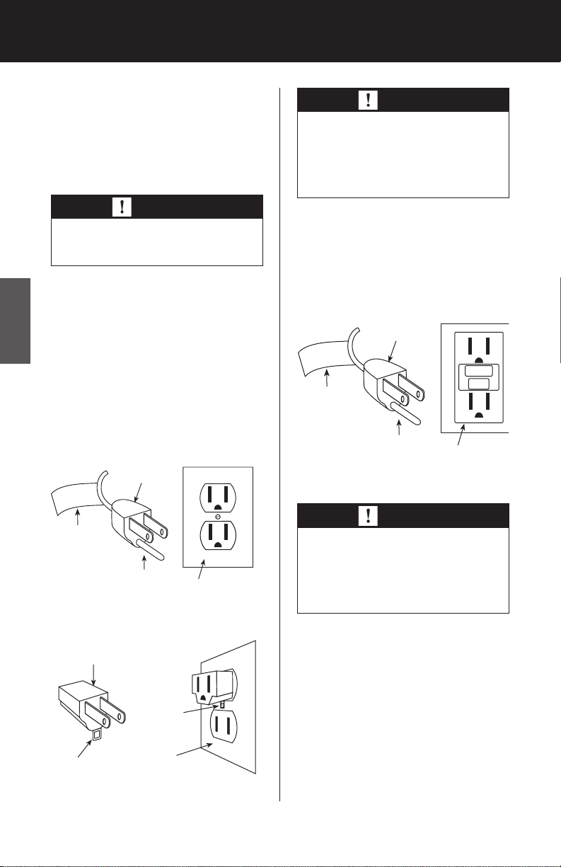
groundIng InStruCtIonS
Grounded Outlet
Grounded
Plug
Grounding Pin
GFCI Tag
Grounded Outlet
Box Cover
Metal
Screw
Adapter
Grounding
Means
GFCI Receptacle
Grounded
Plug
Grounding Pin
GFCI Tag
This appliance is for household use
only and may be plugged into any
120-volt AC electrical outlet (ordinary household current). DO NOT
use any other type of outlet.
WarnIng
This unit is suitable for grounded receptacle use only.
The power cord has a grounded plug
as shown in Figure 1A. The fan must
be plugged into an electrical outlet
ENGLISH
that can accommodate the grounding pin. If your electrical outlet can
not accommodate the grounding
pin, then you must purchase and install one of the two types of adapters shown in Figure 1B.
WarnIng
If this fan is to be used outdoors
or in a damp or wet location, then
it must be plugged into a Ground
Fault Circuit Interrupter (GFCI) receptacle.
When the fan is used outdoors or in
a damp or wet location, it must be
plugged into a Ground Fault Circuit
Interruptor (GFCI) receptacle. See
Figure 1C.
FIGURE 1C
WarnIng
To reduce the risk of fire or
electric shock, do not use this
fan with any solid-state speed
control device.
FIGURE 1A
FIGURE 1B
4 42729-01 12/20/2006
aSSembly
LINE CORD SAFETY TIPS
1. NEVER pull or yank on the cord
or the appliance.
2. To insert plug, grasp it firmly
and guide it into the outlet.
3. To disconnect the appliance,
grasp the plug and remove it
from the outlet.
4. Before each use, inspect the line
cord for cuts and/or abrasion
marks. If any are found, the appliance should be serviced and
the line cord replaced. Please
return it to our Service Department or to an authorized service
representative.
5. NEVER wrap the cord tightly
around the appliance, as this
could place undue stress on the
cord where it enters the appliance and could cause it to fray
and break.
6. DO NOT operate appliance if
the line cord shows any damage, if the appliance works
intermittently or stops working
entirely.
DO NOT use an extension cord
7.
with this fan.
note:
Assembly of this fan will
be easier if performed by two
people.
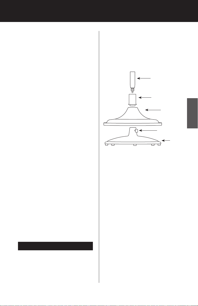
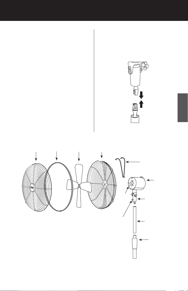
1. Slide the Cover Support Cap
over the bottom of the Telescoping Pole. See Figure 1.
Telescoping Pole
Cover Support Cap
Base Cover
Pole Setscrew
(pre-installed,
tagged)
FIGURE 1
2. Insert the bottom of the Telescoping Pole through the Base
Cover. See Figure 1.
3. Place the bottom of the Tele
scoping Pole into the Cast Iron
Base, making sure the plug connector from the bottom of the
Telescoping Pole goes through
the Cast Iron Base. Twist the
Telescoping Pole clockwise to
secure it into the Cast Iron Base.
Cast
Iron
Base
-
ENGLISH
4. Locate the Pole Setscrew (preinstalled, tagged) in the neck of
preparatIon
1. For Model 9017X, remove the
plastic sleeve from the bottom
of the Telescoping Pole.
the Cast Iron Base. See Figure 1.
5. Use an adjustable wrench to
tighten the Pole Setscrew (preinserted, tagged) until it seats
firmly against the Telescoping
Pole. See Figure 1.
42729-01 12/20/2006 5
aSSembly ContInued
6. Lower the Base Cover over the
Cast Iron Base. See Figure 1.
7. Twist the Cover Support Cap
clockwise into the Cast Iron
Base until it is tight. See Figure
1.
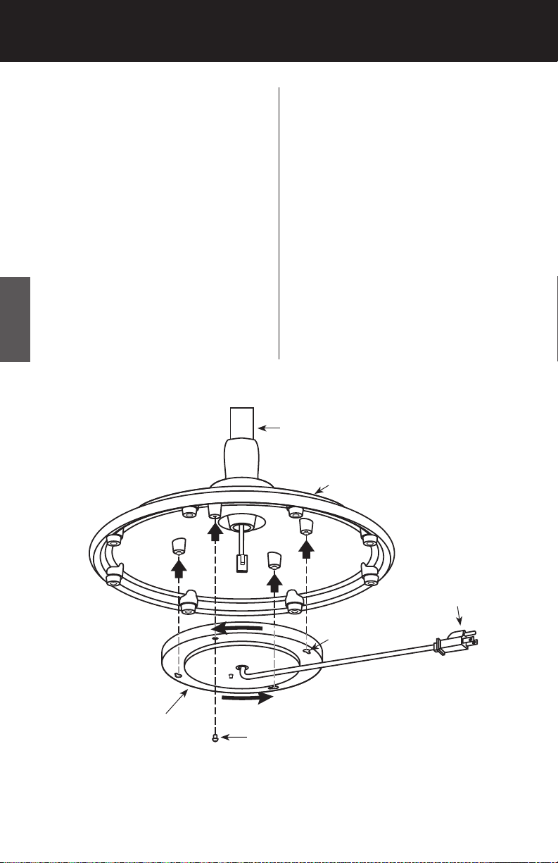
8. Carefully lean the entire assem
bly over so it rests on its side on
the floor.
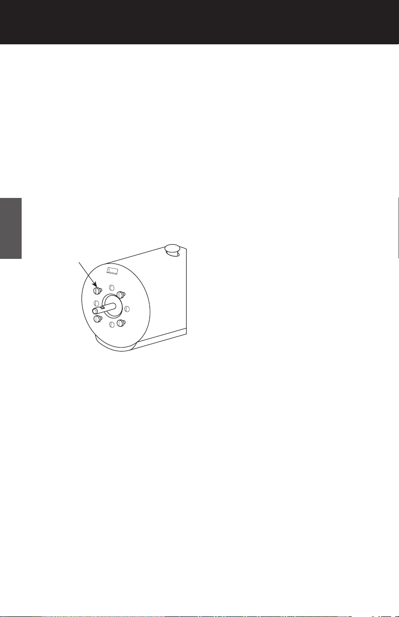
9. Remove one of the four Cover
Assembly Screws from the bottom of the Cast Iron Base and
ENGLISH
loosen the three remaining Cover Assembly Screws. See Figure
2.
-
10. Connect the plugs coming from
the bottom of the Telescoping
Pole and the insdie of the Electrical Cover.
11.
Place the Electrical Cover
against the bottom of the Cast
Iron Base and align the Keyslots
in the Electrical Cover with the
three loosened Cover Assembly
Screws. Rotate the Electrical
Cover counterclockwise. See
Figure 2.
12. Install the fourth Cover Assem
bly Screw. Tighten all four Cover
Assembly Screws to attach the
Electrical Cover to the bottom
of the Cast Iron Base.
Telescoping Pole
Base
-
Wall
Plug
Keyslots
Electrical
Cover
6 42729-01 12/20/2006
Cover Assembly Screw
FIGURE 2
13. Hold the wall plug out of the
way and stand the fan upright.
14. Loosen the Height Adjustment
Grip on the Telescoping Pole by
turning it counterclockwise. See
Figure 3. Raise theTelescoping
Pole approximately 10 inches.
Turn the Height Adjustment
Grip clockwise to set the height
of the Telescoping Pole.
16. Connect the plugs coming from
the bottom of the Motor Mount
and the top of the Telescoping
Pole. See Figure 4.
15. Remove the Motor Mount Set
screw (pre-loaded and tagged)
and set it aside for later reinstallation. See Figure 3.
Front
Grille
Grille
Ring
Blade
Assembly
-
ENGLISH
FIGURE 4
Back
Grille
Interlock Bracket
Fan
Motor
Motor
Motor Mount
Setscrew
(pre-loaded
and tagged)
Face
Motor
Mount
Telescoping
Pole
Height
Adjustment
Grip
FIGURE 3
42729-01 12/20/2006 7
aSSembly ContInued
ENGLISH
Upper
8 42729-01 12/20/2006
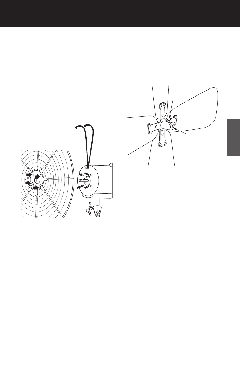
20. Align the three keyhole slots in
the Back Grille with the three remaining Grille Mounting Screws
in the Motor Face, and place the
Back Grille onto the Motor Face,
ensuring that the Grille Mounting Screw washers are between
the screw head and the Back
Grille. If necessary, loosen the
three remaining Grille Mounting
Screws. See Figure 7.
23. Loosen the Blade Assembly
Setscrew so that it does not
protrude into the inside of the
Blade Assembly Sleeve. See Figure 8.
Blade
Assembly
Setscrew
Blade
Assembly
Sleeve
FIGURE 8
ENGLISH
FIGURE 7
21. Rotate the Back Grille clockwise
to situate the screws in the narrow ends of the keyhole slots.
22. Reinstall and tighten the Up
per Left Grille Mounting Screw
and tighten the remaing three
remaining Grille Mounting
Screws.
42729-01 12/20/2006 9
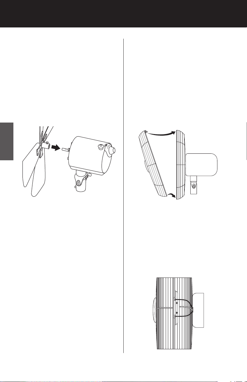
24. Slide the Blade Assembly Sleeve
over the Motor Shaft, ensuring
the Blade Assembly Screw is positioned over the Flat Portion of
the Motor Shaft. See Figure 9.
Tighten the Blade Assembly Setscrew so that it seats against the
Flat Portion of the Motor Shaft.
gently pull the Blade Assembly
to ensure it is secure on the Motor Shaft.
ENGLISH
25. With the Hunter logo facing forward and upright, engage the
tabs on the lower part of the
Front Grille into the rim of the
Back Grille, as shown in Figure
10, arrow 1. Then, move the
top of the Front Grille as shown
in Figure 10, arrow 2, so that
the tab at the top of the Front
Grille snaps under the rim of the
Back Grille.
2
FIGURE 9
NOTE: For clarity, the Back Grille
and Interlock Bracket have been
removed from Figure 9 to show the
Blade Assembly Sleeve/Motor Shaft
installation.
26. Align the two ends of the Inter
lock Bracket with the two notches
in the tab on top of the Front
Grille. Press the two ends of the
Interlock Bracket into the two
1
FIGURE 10
-
notches of the tab on the top of
the Front Grille. See Figure 11.
FIGURE 11
10 42729-01 12/20/2006
operatIon
27. Place the Grille Ring over the
Front and Back Grille rims, positioning the opening of the
Grille Ring at the bottom of the
Front and Back Grille rims. Bring
the two ends of the Grille Ring
together, and secure them with
Grille Ring Latch. See Figure 12.
This appliance is for household use
only.
1. Place the fan on a dry, safe, flat
surface where it cannot fall or
be pulled by the cord.
2.
The Power/Speed Control
should always be OFF before
plugging or unplugging the fan.
Plug the fan into a grounded
120-volt AC electrical outlet
(ordinary household current).
DO NOT use any other type of
outlet. Make sure that the rated
voltage of the fan is the same as
the power source before plugging it into the power source.
3.
Use the Power/Speed Control
to turn the fan “ON” or “OFF”.
See Figure 13.
4. To select the speed, move the
Power/Speed Control from OFF
to the desired speed setting:
O (off), I (low), II (medium), III
(High). See Figure 13.
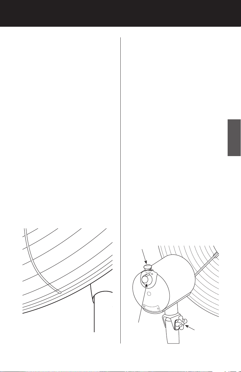
ENGLISH
Oscillation Pin
Power/Speed
Control
FIGURE 13
42729-01 12/20/2006 11
Angle
Adjustment
Knob

5. To adjust the upward or down
ward flow of air, loosen the Angle Adjustment Knob beneath
the Fan Motor. See Figure 13.
Position the fan to the desired
angle, and tighten the Angle
Adjust knob.
6. To make the fan oscillate, push
the Oscillation Pin down. To
stop the fan from oscillating,
pull the Oscillation Pin up. See
Figure 13.
7. To adjust the height of your
ENGLISH
fan, hold the Telescoping Pole
securely with one hand, and
twist the Height Adjustment
Grip counterclockwise. While
supporting the fan motor, raise
or lower the Telescoping Pole to
the desired height, then tighten
the Height Adjustment Grip.
maIntenanCe
This fan is permanently lubricated
and will not require additional lubrication (oil) for the life of the fan.
This fan requires little maintenance
and contains no user serviceable
parts. DO NOT try to fix it yourself.
Contact qualified service personnel if
servicing is needed.
-
2. DO NOT immerse the fan in wa
ter or any other liquid.
CLEANING GRILLE AND BLADES
1. Turn the fan off and remove the
plug from the electrical outlet.
2. To disassemble the Grille, un
latch the Grille Ring Latch,
remove the Grille Ring and the
Interlock Bracket.
3. Loosen the Blade Assembly
Setscrew and slide the Blade Assembly off of the Motor Shaft.
4. The Grilles and the Blade Assem
bly may be cleaned with mild
soap and water.
5. Use a soft, slightly damp cloth
to wipe the remaining fan parts.
6. When the Blade Assembly and
Grilles have dried completely,
reassemble the fan following
assembly steps 18 - 27 of this
manual.
7. DO NOT plug fan into an elec
trical outlet until it has been
fully reassembled.
-
-
-
-
TO CLEAN:
1. Before cleaning, turn the fan
off and remove the plug from
electrical outlet. Wipe off excess
dust with a lint-free cloth.
12 42729-01 12/20/2006

Storage
troubleShootIng
1. To store the fan, disassemble
the Front and Back Grilles,
remove the Blade Assembly,
and clean the entire fan with a
damp cloth.
2. ALWAYS store the fan in a dry
place.
3. NEVER store the fan while it is
still plugged in.
4. NEVER wrap the cord tightly
around the fan.
5. DO NOT put any stress on the
cord where it enters the fan, as
it could cause the cord to break.
PROBLEM
• Fan will not work.
SOLUTION
• Make sure the Interlock Bracket is
properly installed as directed in the
assembly instructions. See page 9.
PROBLEM
• Fan will not oscillate.
ENGLISH
SOLUTION
• Push down the Oscillation Pin on
top of motor housing to activate
oscillation. See page 11.
PROBLEM
• Can not adjust the angle of the
fan.
SOLUTION
• Loosen the Angle Adjustment
Knob on the side of the fan neck.
Adjust to the desired angle and
tighten the knob. See page 11.
If you have tried these troubleshooting solutions and still have
trouble, visit our Web site at http:
//www.hunterfan.com.
HUN TE R FA N COM PAN Y
2 50 0 F R IS CO A V EN U E
MEMPHIS, TN 38114, USA
©
42729-01 12/20/2006 13
2006 Hunter Fan Co.
Printed in China
 Loading...