

Page 1
I n s t a l l a t i o n G u i d e
ENG LISH
See page 2
Vea la página 19
ESpañoL
Energy Star Bath Fan Models 82043
READ and SAVE THESE INSTRUCTIONS
1
43045-01 10/15/2009
Page 2
W A R N I N G
TO REDUCE THE RISK OF ELECTRIC SHOCK OR INJURY, OBSERVE THE FOLLOWING:
1) Read all instructions before attempting to install or use this appliance. This appliance is for general ventilating
use only. Do not use this appliance for ventilating hazardous or explosive materials. Follow the heating equipment
manufacturer’s guideline and safety standards, such as those published by the National Fire Prevention Association
(NFPA), and the American Society for Heating, Refrigeration and Air-Conditioning Engineers (ASHRAE), and the
local code authorities.
by the manufacturer may cause fire, electric shock, or injury to persons. SAVE THESE INSTRUCTIONS.
2)
Before installing, servicing, or cleaning the unit, disconnect the power by turning off the circuit breakers to the
outlet box and associated wall switch location. If you cannot lock the circuit breakers in the off position, securely
attach a prominent warning device, such as a tag, to the service panel.
3)
This unit must be grounded.
4)
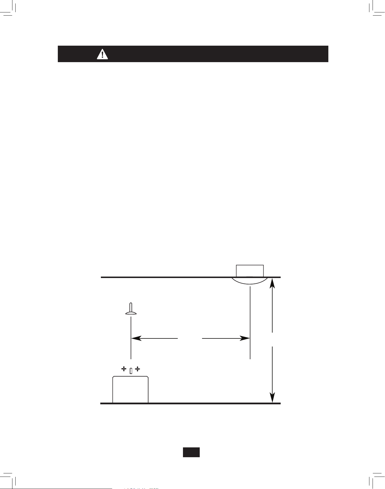
This appliance is not suitable for tub or shower installation, and must not be installed within a minimum of 3 feet
from the tub or shower opening. See Figure A.
5)
Do not install this appliance lower than 7 feet (2.13 m) above the floor in the ceiling. See Figure A.
Use this appliance only as described in this manual. Any other use not recommended
NOTE: This illustration is not
to scale
3 ft. min.
(0.91 m)
Tub or Shower area
Figure A
Bath Fan
7 ft. min.
(2.13 m)
Continued
2
43045-01 10/15/2009
Page 3
6)
Never place a switch where it can be reached from a tub or shower. Do not install this appliance in a tub or
shower enclosure.
7)
Installation work and electrical wiring must be done by qualified person(s) in accordance with all applicable codes
and standards, including fire-rated construction codes and standards.
8)
When cutting or drilling into wall(s) or ceiling, do not damage electrical wiring or other hidden utilities.
9) Do not install this product in a wall. This product is designed for installation in ceilings up to a 12/12
pitch (45 degrees). Ductwork must point upward.
10)
Ducted fans must always be vented to the outdoors. Keep ducting as short and as straight as possible.
11) Extreme caution is necessary when any is used by or near children or invalids and whenever the is
left operating and unattended.
12) To avoid motor bearing damage and noisy/unbalanced blower wheel, keep drywall spray, construction
dust, etc. off power unit.
13) Read specification label on product for further information and requirements.
14) Do not insert or allow foreign objects to enter any ventilation or exhaust opening as this may cause an
electric shock or fire, or damage the unit.
15)
Do not use this appliance with a dimmer switch or a fan speed controller.
16) To reduce the risk of fire or electrical shock, do not use this fan with any solid-state speed control device.
17) To prevent a possible fire, do not block air intakes or exhaust in any manner.
18) If this unit is to be installed over a tub or shower, it must be marked as appropriate for the application
and be connected to a GFCI (Ground Fault Circuit Interrupter)-protected branch circuit.
3
43045-01 10/15/2009
Page 4
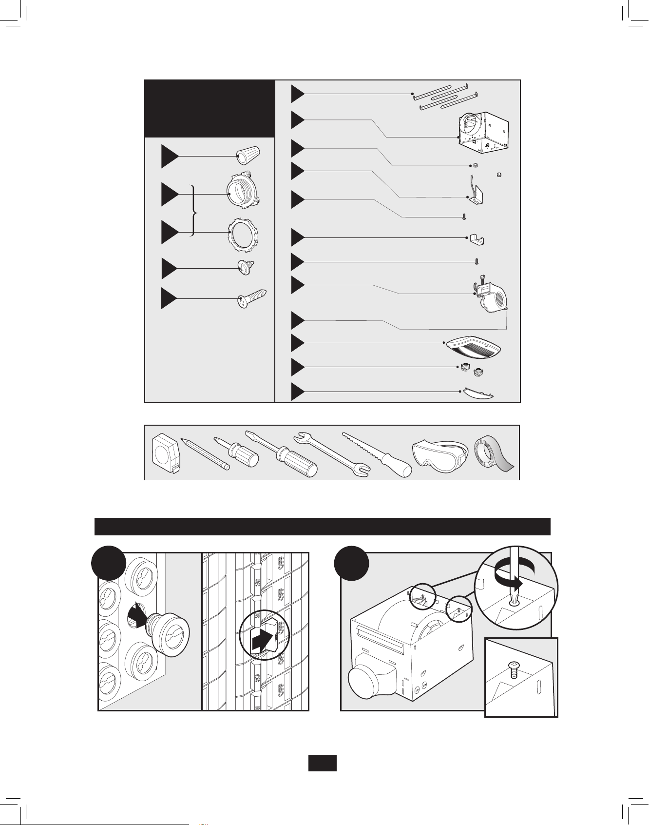
Check all the parts. If damaged, call
1-888-830-1326 for replacement.
x6
A
x2
F
G
H
I
95044-01-000
98141-01-000
75184-01-133
97134-01-000
Mounting Rails
Housing
Light Fixture Thumbnuts
B
*
3/8” Cable Connector
C
*
D
x2
x4
*
NOTE:
Attachment Screws
E
Mounting Screws
Strain relief (not supplied) cable
connector must be installed.
x2
J
K
L
M
N
O
P
Q
03242-07-133
65827-01-000
74508-53
98142-01-000
74508-03-133
96932-01-000
97932-01-262
87258-01-000
87259-01-000
Included.
Wiring Cover
Wiring Cover Screw
Strain Relief Bracket
Strain Relief Bracket Screw
Fan Assembly
Fan Mounting Screws
Light Fixture
Light Bulbs
Lens
Before Installation
A
Turn off the power source.
Tools Needed. (Not supplied.)
Estimated assembly time: 30 to 60 minutes
B
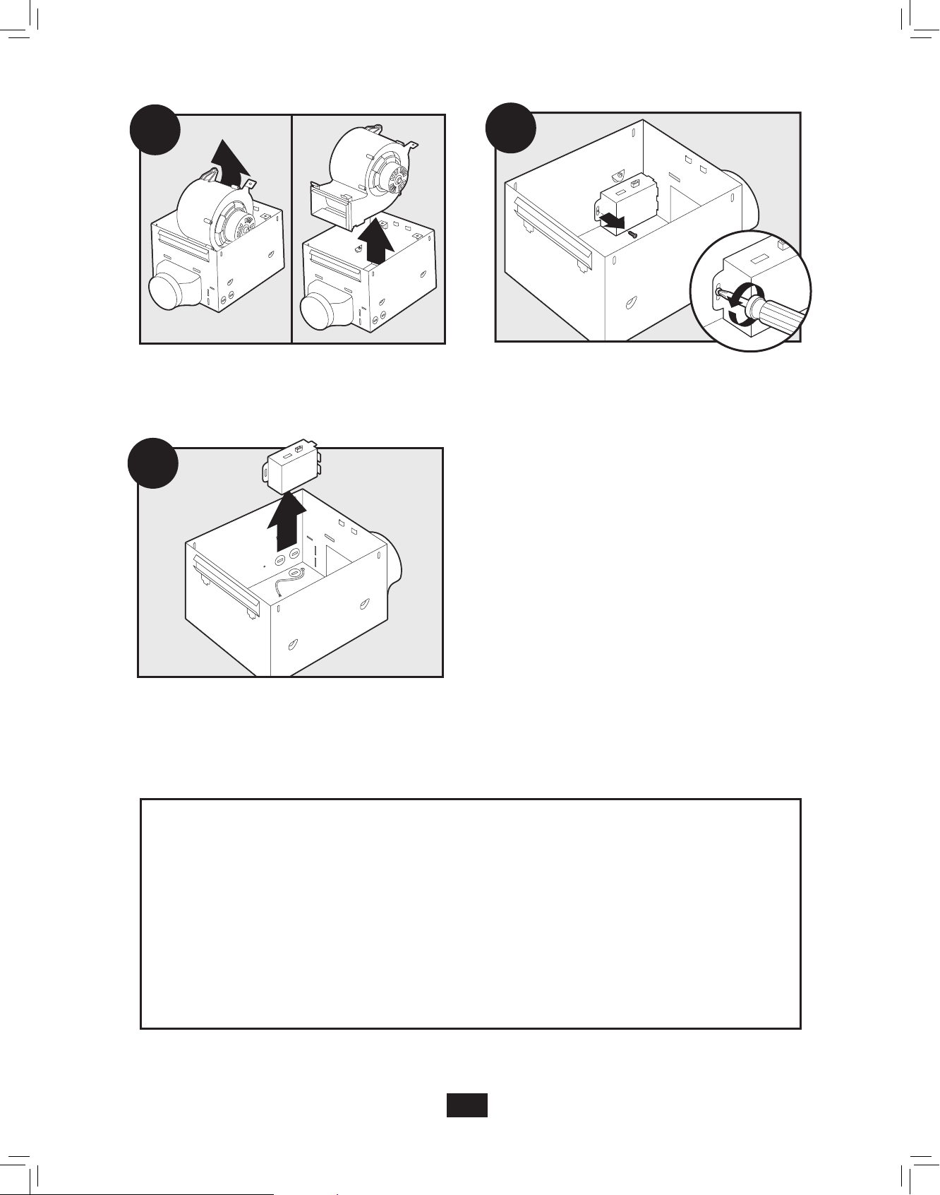
Loosen the fan mounting screws.
4
43045-01 10/15/2009
Page 5
C
D
Remove the fan assembly from the housing.
E
Remove the wiring cover.
Loosen the wiring cover screw.
Choose Installation Option
For New Construction - attaching to joist, go to step A1, page 5.
For New Construction - suspended between, joists go to step B1, page 7.
For Existing Construction - accessible from above, go to step C1, page 9.
For Existing Construction - accessible only from below, go to step D1, page 12.
5
43045-01 10/15/2009
Page 6
Section A - New Construction - attaching to joist
A1
OR
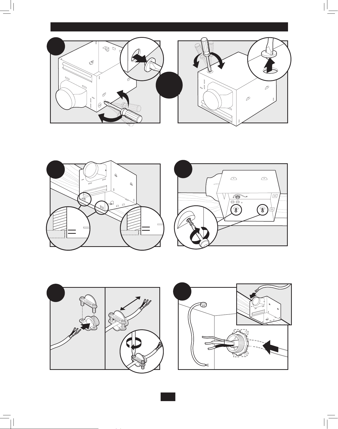
Pop out a wiring access slug.
A2
5/8
1/2
joist based upon the the thickness of your sheetrock.
A4
3”
A3
5/8
1/2
Drive mounting screws (supplied) into joist or framing.Position the correct depth mark at the bottom edge of the
A5
Run the power supply wire through the strain relief, leaving
3” between the end of the wire and the strain relief. Tighten
the strain relief around the wire.
43045-01 10/15/2009
Install the wiring and the strain relief into the wiring access
hole you made earlier.
6
Page 7
A6
5/8
1/2
Instalación Final
en la página 14.
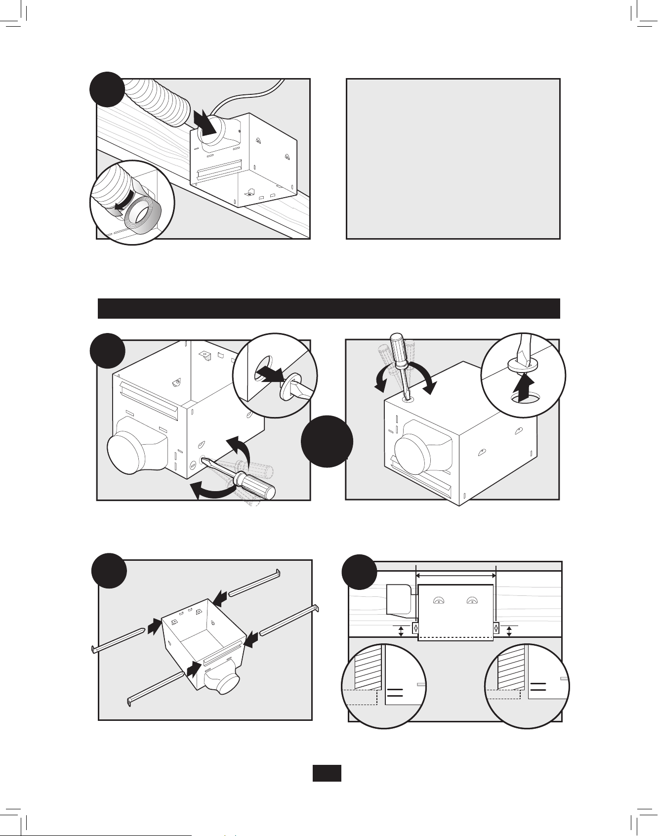
Connect 6” duct and vent to the outside. Use duct tape to
secure joints. If ducting does not fit securely, an adapter
may need to be purchased.
Section B - New Construction – suspended between joists
B1
Vaya a la
sección E –
B2
OR
Pop out a wiring access slug.
B3
5/8
1/2
Slide the mounting rails into brackets. Note the orientation
of of the outer ends of the rails.
43045-01 10/15/2009
Position the correct depth mark at the bottom edge of the
joist based upon the the thickness of your sheetrock.
7
Page 8
B4
B5
1/16” bit
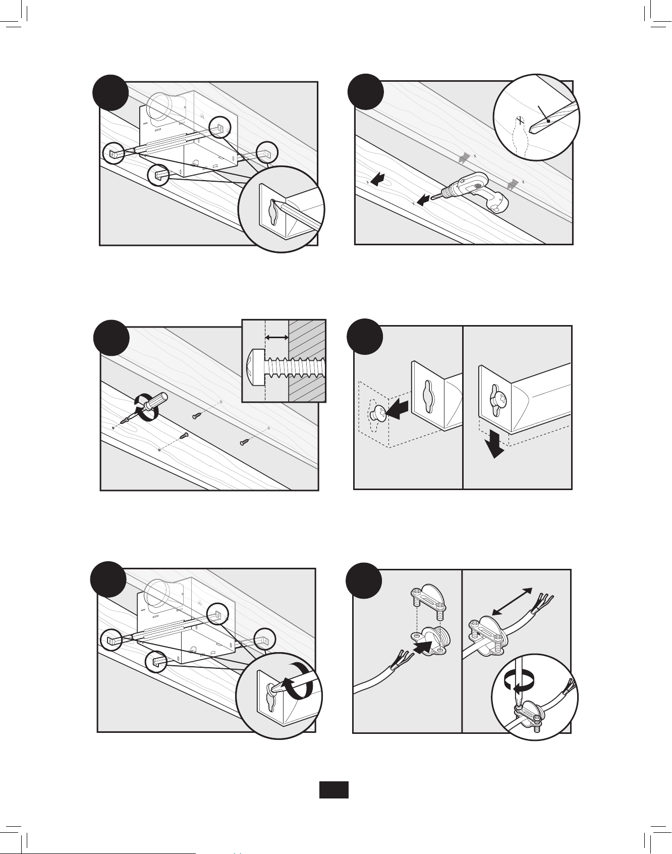
Mark position of screws by using holes as a template.
B6
Insert mounting screws, leaving space between the screw
head and the joist. (Screws are supplied.)
Drill a pilot hole at the TOP of each outline.
B7
Attach the rails onto the screws.
B8
Tighten screws.
B9
3”
Run the power supply wire through the strain relief, leaving
3” between the end of the wire and the strain relief. Tighten
the strain relief around the wire.
8
43045-01 10/15/2009
Page 9
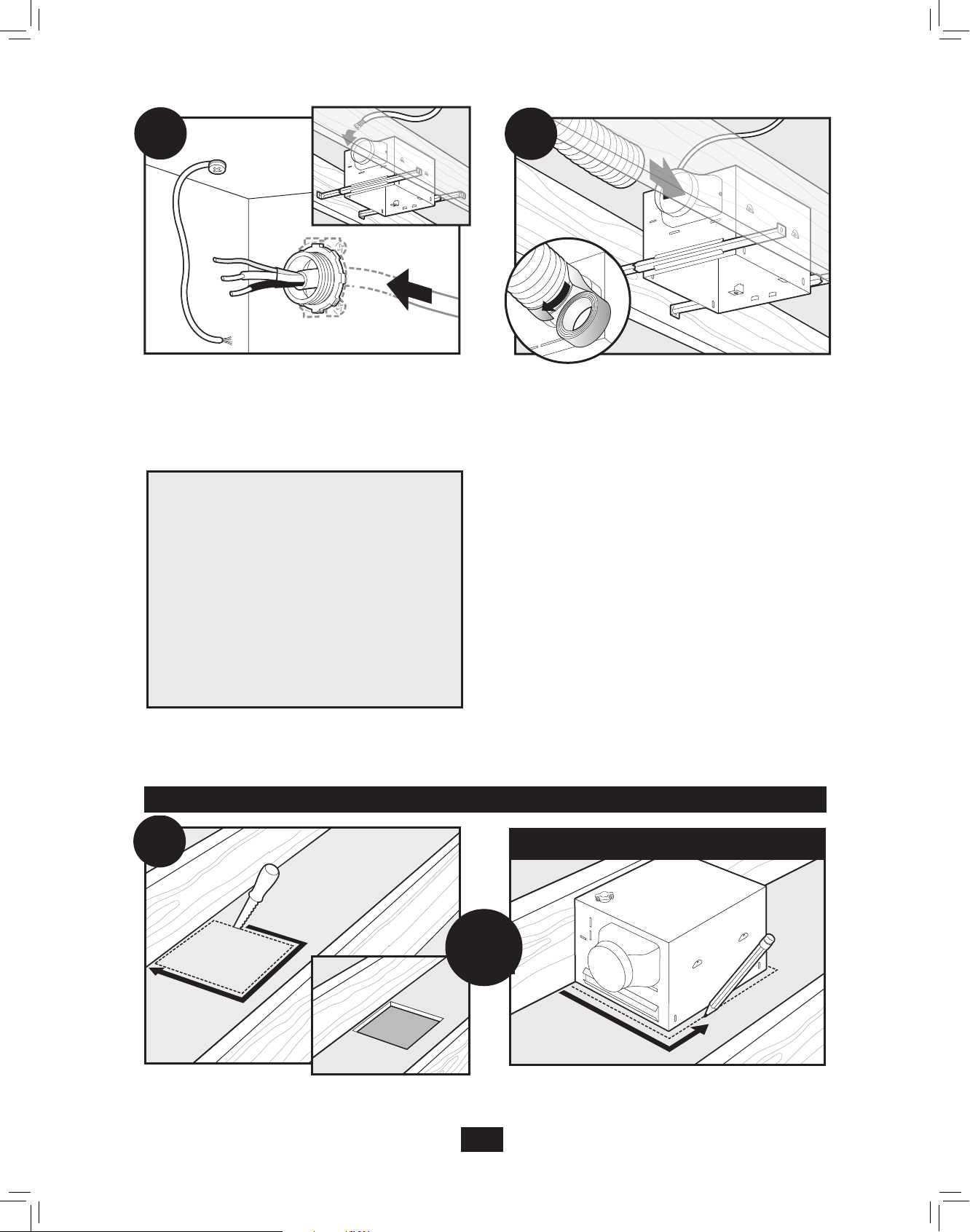
B10
B11
Install the wiring and the strain relief into the wiring access
hole you made earlier.
Connect 6” duct and vent to the outside. Use duct tape to
secure joints. If ducting does not fit securely, an adapter
may need to be purchased.
Vaya a la
sección E –
Instalación Final
en la página 14.
Section C - Existing Construction – accessible from above
C1
11”
Remove an existing fan and check to make sure the opening
is large enough to accommodate the new fan housing. The
9 5⁄8”
opening needs to be 11” x 9 5/8”.
43045-01 10/15/2009
NO EXISTING FAN
OR
9
Page 10
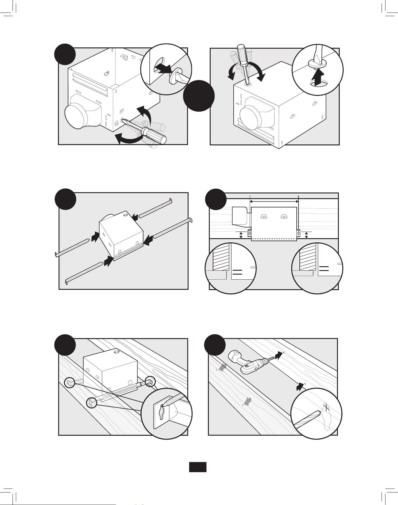
5/8
1/2
C2
OR
Pop out a wiring access slug.
C3
C5
Slide the mounting rails into brackets.
C4
5/8
1/2
Using the depth markings on the housing, position the
bottom edge of the housing so that it will be flush with the
sheetrock.
C6
Mark position of screws by using holes as a template.
43045-01 10/15/2009
Drill a pilot hole at the TOP of each outline, AS SHOWN.
10
Page 11
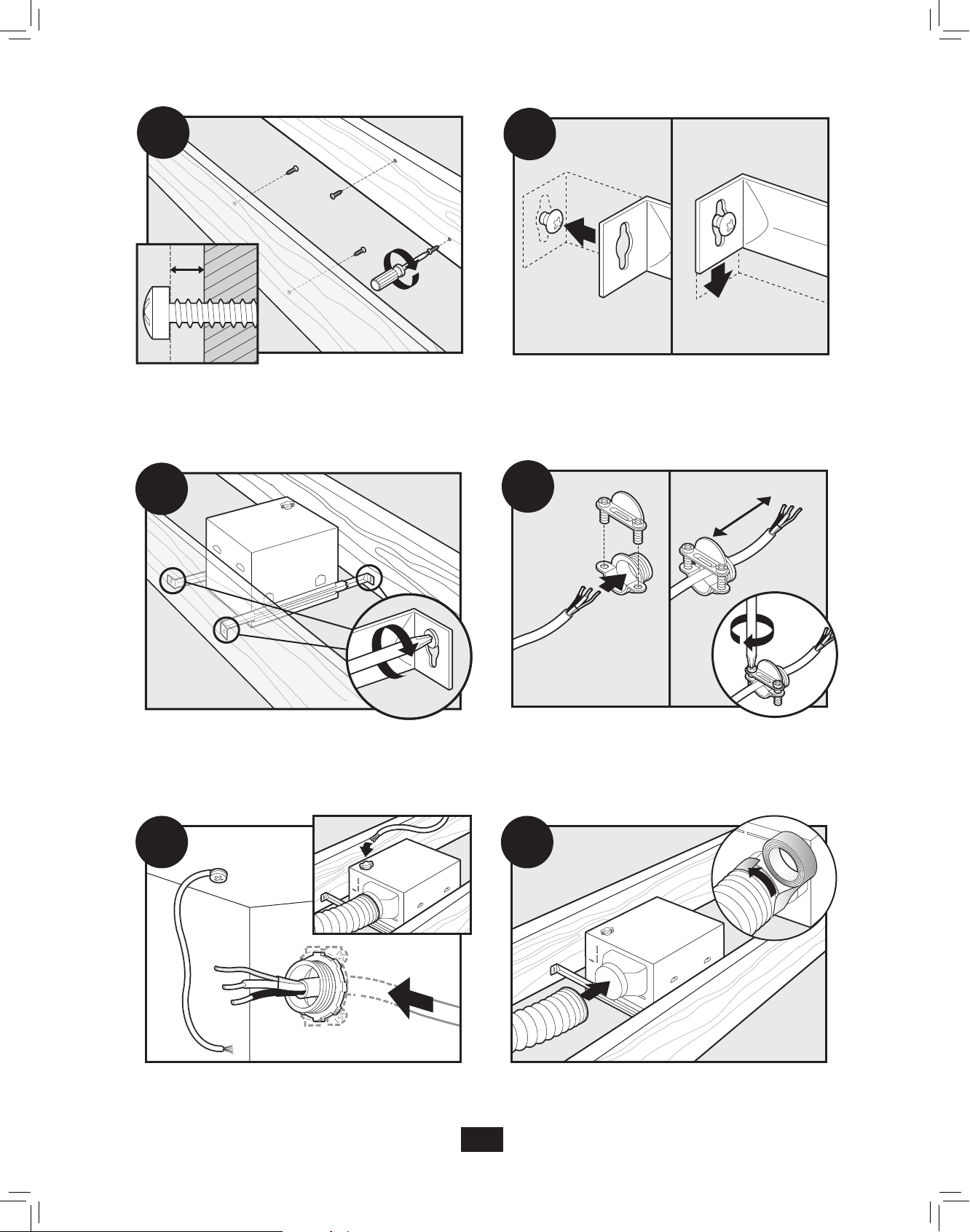
C7
C8
Insert mounting screws, leaving space between the screw
head and the joist. (Screws are supplied.)
C9
Tighten screws.
Attach the rails onto the screws.
C10
3”
Run the power supply wire through the strain relief, leaving
3” between the end of the wire and the strain relief. Tighten
the strain relief around the wire.
C11
Install the wiring and the strain relief into the wiring access
hole you made earlier.
43045-01 10/15/2009
C12
Connect 6” duct and vent to the outside. Use duct tape to
secure joints. If ducting does not fit securely, an adapter
may need to be purchased.
11
Page 12
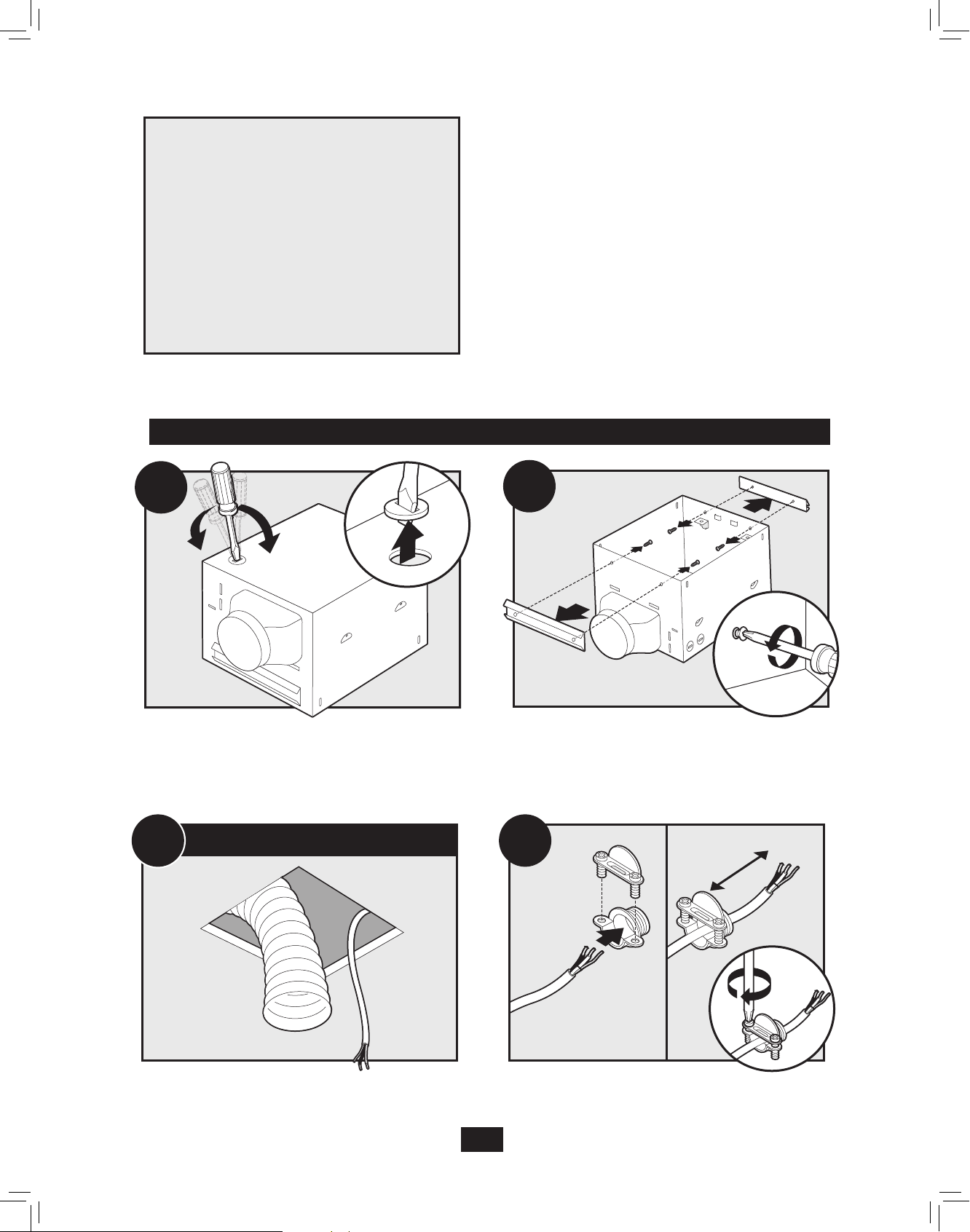
Vaya a la
sección E –
Instalación Final
en la página 14.
Section D - Existing Construction – accessible from below
D1
Remove one of the wiring access slugs on the top of the
housing. Use a second wiring access plug if needed.
D3
EXISTING FAN
D2
Remove the mounting rail brackets.
D4
3”
Remove an existing fan and check to make sure the opening
is large enough to accommodate the new fan housing. If
there is no existing fan choose an appropriate location to
make an 11” x 9 5/8” opening.
43045-01 10/15/2009
Run the power supply wire through the strain relief, leaving 3”
between the end of the wire and the strain relief. Tighten the
strain relief around the wire.
12
Page 13
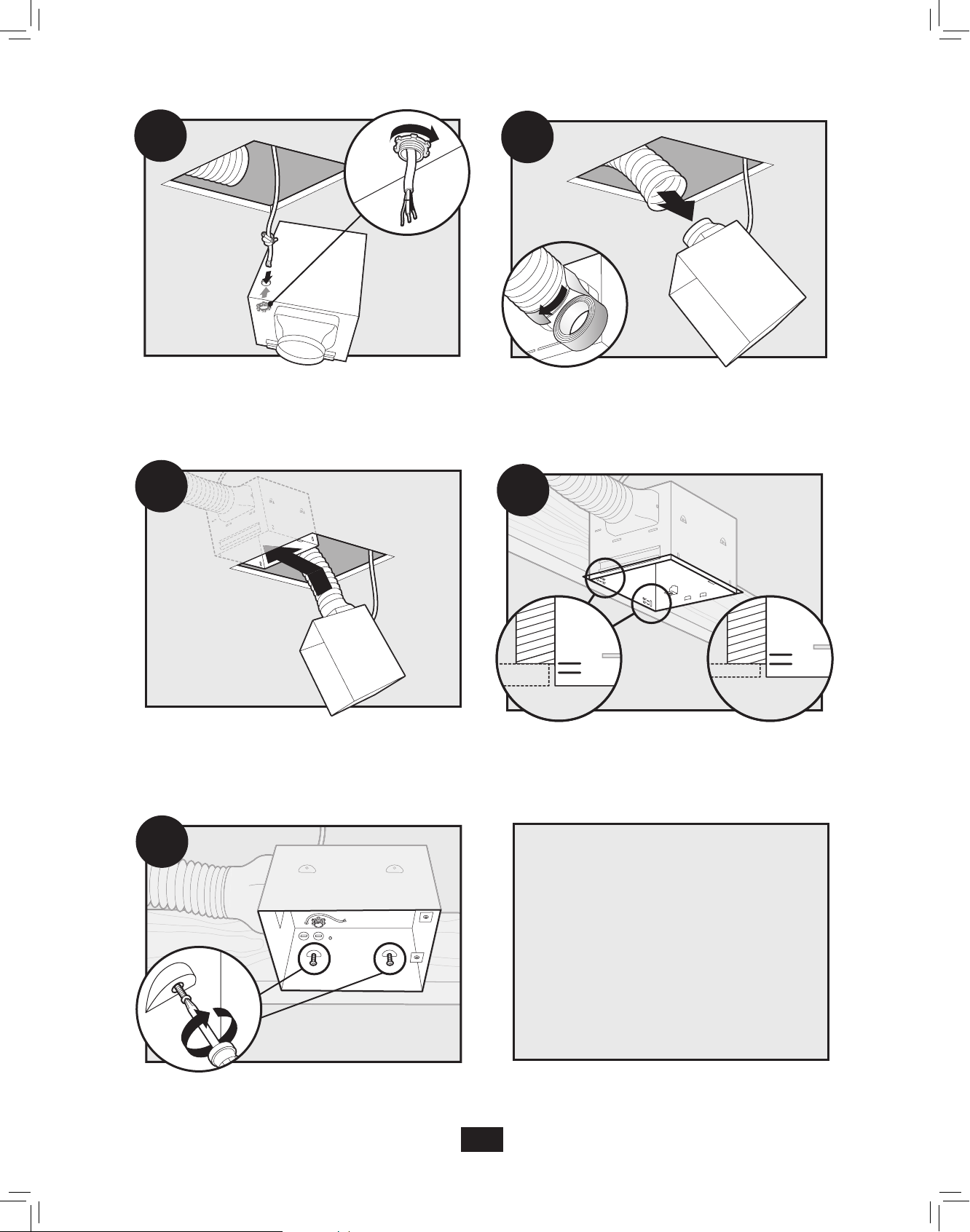
D5
D6
Install the wiring and the strain relief into the wiring access
hole you made earlier.
D7
Move the housing into the ceiling.
Connect 6” duct and vent to the outside. Use duct tape to
secure joints. If ducting does not fit securely, an adapter
may need to be purchased.
D8
5/8
1/2
Position the bottom edge of the housing flush with the
sheetrock.
5/8
1/2
D9
Vaya a la
sección E –
Instalación Final
en la página 14.
Screw mounting screws into joist or framing.
13
43045-01 10/15/2009
Page 14
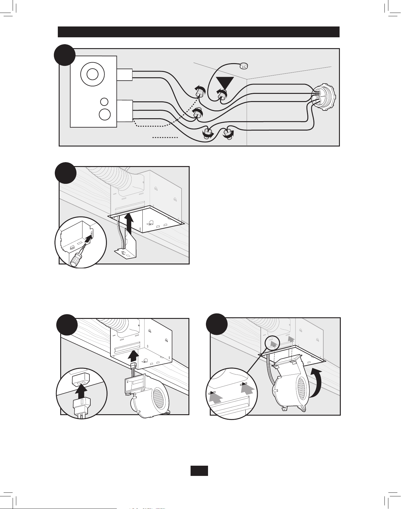
Section E - Final Installation
E1
E2
2 Pin
Fan Motor
Night Light
Light
*Option Fan & Main Light Together
3 Pin
Black
White
White
Red
Night Light
Black
*Option
Light
Connect the wiring as shown.
Ground
Green
A
Bare Copper
Black
Main Switch 1 (AC In)
White
Red
Switch 1 (AC In)
Black
Switch 2 (AC In)
Install the wiring cover box. Make sure all wiring connec-
E3
Connect fan wiring harness. DO NOT ALLOW THE FAN TO
HANG FROM THE WIRING HARNESS. INSTALLATION IS
tions are inside the wiring cover box.
NOTE: Though this final installation section shows the housing mounted to a joist, the final installation procedure is the same
whether the housing is mounted to a joist or suspended between joists.
E4
Install the fan assembly by inserting the tabs as shown and
pushing the fan assembly into the housing. Make certain the
EASIER IF TWO PEOPLE ARE INVOLVED.
wiring is not pinched between the fan
assembly and the housing.
14
43045-01 10/15/2009
Page 15
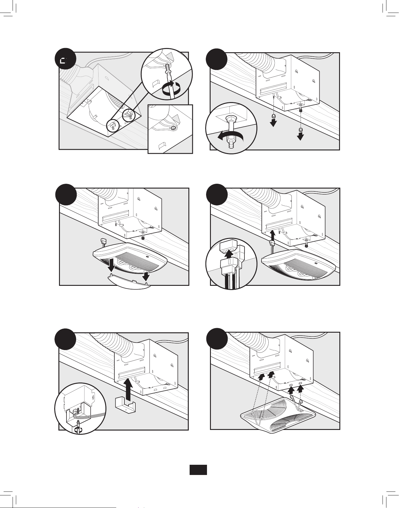
E5
E6
Secure the fan assembly by tightening the two fan mounting
screws.
E7
Remove light bulb cover. Plug in wiring harness.
Remove thumbnuts.
E8
E6
Install the strain relief bracket. DO NOT ALLOW THE
LIGHT FIXTURE TO HANG FROM THE WIRING HARNESS.
INSTALLATION IS EASIER IF TWO PEOPLE ARE INVOLVED.
43045-01 10/15/2009
E7
Position lighting fixture over mounting posts.
15
Page 16
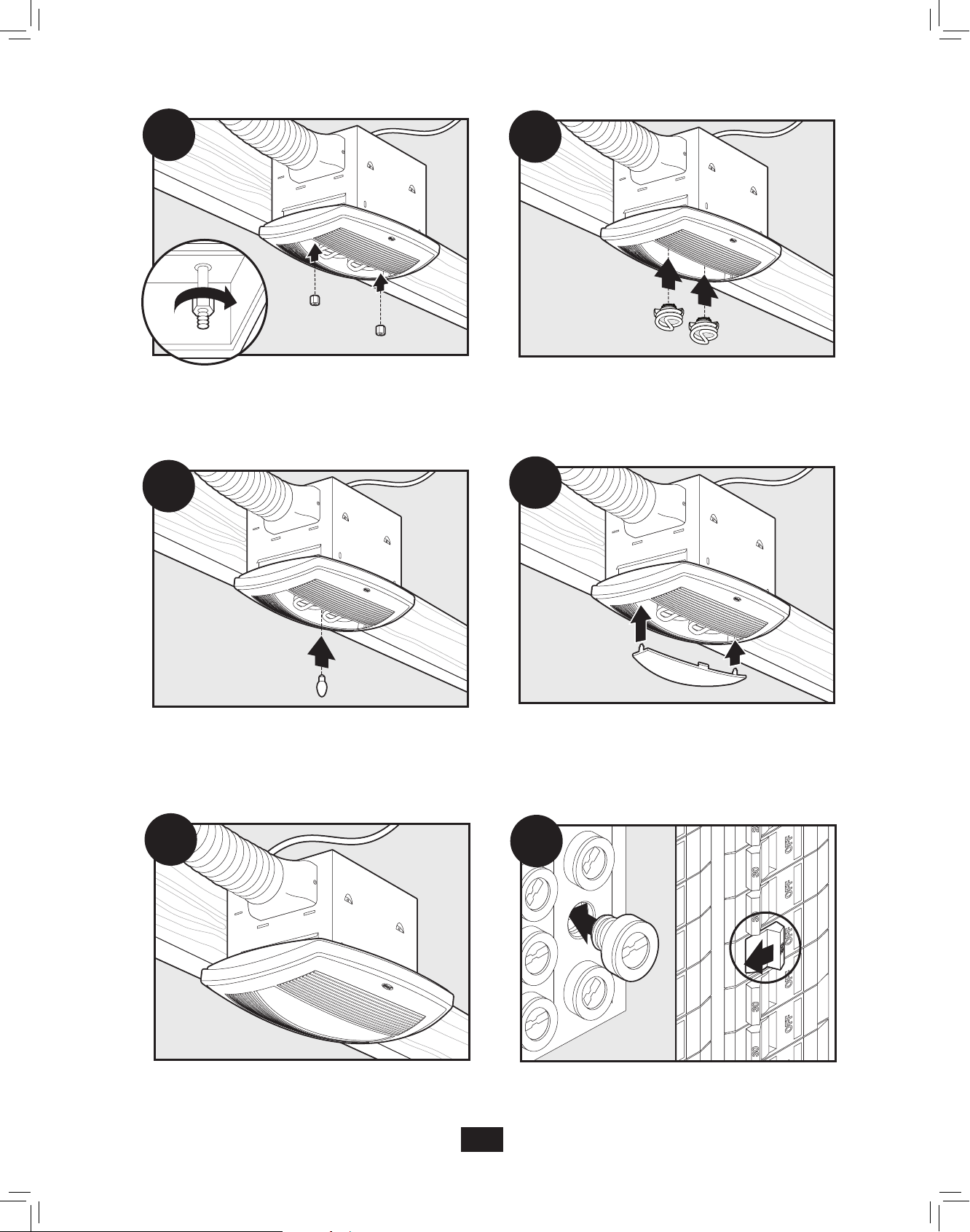
E11
E12
Secure the fan assembly by tightening the two fan mounting
thumbnuts.
E12
Install night light.
Install light bulbs.
E13
Install light bulb cover.
E15
Complete.
E9
Restore power at the source.
16
43045-01 10/15/2009
Page 17

Preventative Maintenance
A clean fan provides better service. Disconnect the power supply and clean the fan as listed below.
TO CLEAN THE BEZEL: Carefully pull the bezel down. Use water, a mild detergent such as dishwashing liquid, and a soft
cloth to clean the bezel. DO NOT use abrasive cloths, steel wool pads, or scouring powders. Dry the bezel and reinstall it.
TO CLEAN THE FAN ASSEMBLY: Disconnect power to the unit by switching off the breaker or removing the fuse. Turn the
wall switch off. Remove the bezel (as described above). Remove the two fan mounting screws. Remove the fan from the housing and unplug the fan wiring harness.
Gently vacuum the fan, motor, and the housing interior.
When the fan is clean, plug in the fan wiring harness. Reinstall the fan and tighten the two fan mounting screws. Reinstall the
bezel.
Restore power to the appliance. Test the appliance. If the fan does not run, 1) check the power source, or 2) disconnect power
to the appliance, disassemble as described above, check the fan assembly plug, restore power, and test the unit. If the fan still
does not run, contact a qualified installer.
NEVER IMMERSE METAL OR ELECTRICAL COMPONENTS IN WATER.
Maintenance
The fan motor is permanently lubricated and never needs oiling. If the motor bearings are making excessive or unusual noises, contact Hunter Technical Support (see Troubleshooting section) to order a new fan assembly.
Trouble Shooting
Problem: Fan does not come on.
Solution:
• Turn power on, replace fuse, or reset breaker.
• Hunter Fan Bath Ventilators are extremely quiet. To conrm that the fan is running, place your hand near the vents to feel
the air movement.
• Check all plug connections to be sure they are secure.
• Check the wiring to make sure it matches the wiring diagram.
Problem: Fan is noisy.
Solution:
• Check and tighten all fasteners.
• Check the bezel to make sure it is secure.
• Check the apper to make sure it moves freely.
17
43045-01 10/15/2009
Page 18
Trouble Shooting (cont.)
If you need parts or service assistance, please call 888-830-1326 or visit us at our website at http://www.hunterfan.com.
Warranty
Hunter Fan Company
Bath Fan
LIMITED WARRANTY
Hunter Fan Company makes the following limited warranty to the original user or consumer purchaser of this Hunter Bath
Fan:
If any part of your Hunter Bath Fan fails at any time within one year after the date of sale to you due to a defect in material or
workmanship, we will repair or, at our option, replace the defective part free of charge for parts and labor performed at our Service
Department in Memphis, Tennessee. After this one-year period, you will be responsible for all parts and labor costs for repairs on
the Bath Fan except for motor repairs as provided below.
If your Hunter Bath Fan motor fails at any time within ve years after the date of sale to you due to a defect in material or workmanship, labor and materials to repair the defect will be provided free of charge at our Service Department in Memphis, Tennessee. If
no replacement part can be provided, we will, at our option, either refund the actual purchase price of your Bath Fan or provide a
replacement free of charge. After this ve-year period, you will be responsible for all parts and labor costs for repairs on all parts of
the bath exhaust fan.
IF THE ORIGINAL USER OR CONSUMER PURCHASER CEASES TO OWN THE FAN, THIS WARRANTY AND ANY IMPLIED WARRANTY WHICH THEN REMAINS IN EFFECT, INCLUDING BUT NOT LIMITED TO ANY IMPLIED WARRANTY OF MERCHANTABILITY OR
FITNESS FOR A PARTICULAR PURPOSE, ARE VOIDED. NO WARRANTY, EXPRESS OR IMPLIED, INCLUDING ANY WARRANTY OF
MERCHANTABILITY OR FITNESS FOR A PARTICULAR PURPOSE, IS MADE IN RESPECT OF GLASS FIXTURES OR LIGHT BULBS
OR THE FINISH ON ANY METAL PORTION OF THE BATH EXHAUST FAN.
THIS WARRANTY IS IN LIEU OF ALL OTHER EXPRESS WARRANTIES. THE DURATION OF ANY IMPLIED WARRANTY, INCLUDING, BUT NOT LIMITED TO, ANY IMPLIED WARRANTY OF MERCHANTABILITY OR FITNESS FOR A PARTICULAR PURPOSE, IN
RESPECT TO ANY HUNTER FAN BATH FAN MOTOR OR OTHER FAN PART, IS EXPRESSLY LIMITED TO THE PERIOD OF THE
EXPRESS WARRANTY SET FORTH ABOVE FOR SUCH MOTORS OR OTHER PARTS.
This warranty is voided if your Hunter Bath Fan is not purchased and installed in the U.S.A. This warranty excludes and does not
cover defects, malfunctions or failures of any Hunter Bath Fan which were caused by repairs by persons not authorized by us, use
of parts or accessories not authorized by us, mishandling, improper installation, modications or damage to the Hunter Bath Fan
while in your possession, or unreasonable use, including failure to provide reasonable and necessary maintenance.
To obtain servicing, contact Hunter Fan Company Technical Support at 1-888-830-1326. Please contact us before shipping your
Bath Fan to us. If we authorize you to ship it to us, you will be responsible for all insurance and freight or other transportation
charges to our factory or Service Department. We will return your Hunter Bath Fan freight prepaid. Your Hunter Bath Fan should
be properly packed to avoid damage in transit since we will not be responsible for any such damage. Proof of purchase is required
when requesting warranty service. The purchaser must present the sales receipt or other document that establishes proof of
purchase.
IN NO EVENT SHALL HUNTER FAN COMPANY BE LIABLE FOR CONSEQUENTIAL OR INCIDENTAL DAMAGES.
SOME STATES DO NOT ALLOW LIMITATIONS ON HOW LONG AN IMPLIED WARRANTY LASTS OR THE EXCLUSION OR LIMITATION OF INCIDENTAL OR CONSEQUENTIAL DAMAGES SO THE ABOVE LIMITATION OR EXCLUSIONS MAY NOT APPLY TO YOU.
THE WARRANTY GIVES YOU SPECIFIC LEGAL RIGHTS AND YOU MAY ALSO HAVE OTHER RIGHTS WHICH VARY FROM STATE TO
STATE
.
Hunter Fan Company
2500 Frisco Avenue
Memphis, Tennessee 38114
Printed in China
18
43045-01 10/15/2009
 Loading...