

Installation Guide
See page 2
ENGLISH
Vea la página 19
ESPAÑOL
Energy Star Bath Fan Light Models 82040, 82041, 82042
READ and SAVE THESE INSTRUCTIONS
1
42936-01 10/17/2007
3 ft. min.
(0.91 m)
Bath Fan
Tub or Shower area
NOTE: This illustration is not
to scale
7 ft. min.
(2.13 m)
WARNING
TO REDUCE THE RISK OF ELECTRIC SHOCK OR INJURY, OBSERVE THE FOLLOWING:
1) Read all instructions before attempting to install or use this appliance. This appliance is for general
ventilating use only. Do not use this appliance for ventilating hazardous or explosive materials. Follow
the heating equipment manufacturer’s guideline and safety standards, such as those published by
the National Fire Prevention Association (NFPA), and the American Society for Heating, Refrigeration
and Air-Conditioning Engineers (ASHRAE), and the local code authorities.
described in this manual. Any other use not recommended by the manufacturer may cause
fire, electric shock, or injury to persons. SAVE THESE INSTRUCTIONS.
2)
Before installing, servicing, or cleaning the unit, disconnect the power by turning o the circuit
breakers to the outlet box and associated wall switch location. If you cannot lock the circuit breakers
in the o position, securely attach a prominent warning device, such as a tag, to the service panel.
3)
This unit must be grounded.
4)
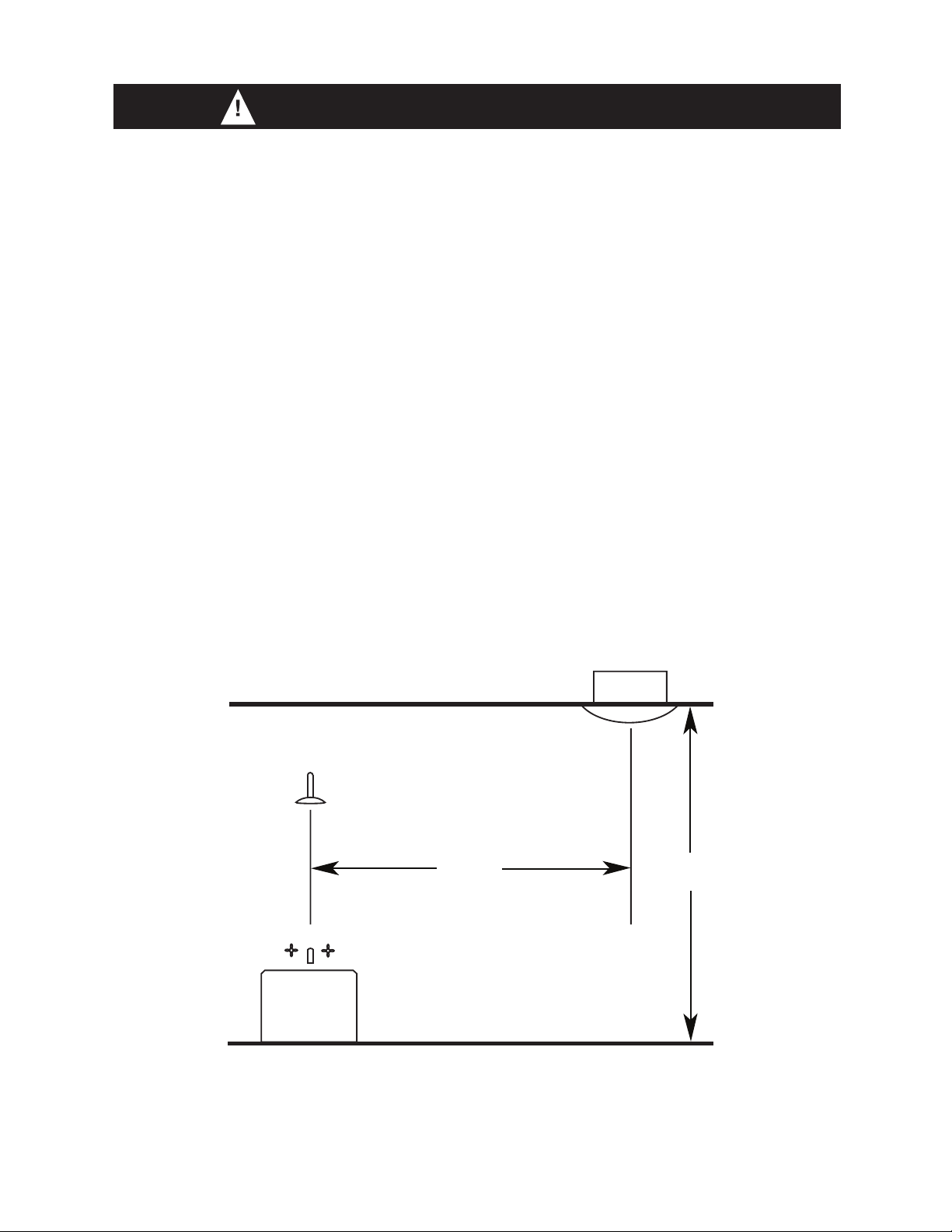
This appliance is not suitable for tub or shower installation, and must not be installed within a
minimum of 3 feet from the tub or shower opening. See Figure A.
5)
Do not install this appliance lower than 7 feet (2.13 m) above the floor in the ceiling. See Figure A.
Use this appliance only as
42936-01 10/17/2007
Figure A
Continued
2

6)
Never place a switch where it can be reached from a tub or shower. Do not install this appliance in
a tub or shower enclosure.
7)
Installation work and electrical wiring must be done by qualified person(s) in accordance with all
applicable codes and standards, including fire-rated construction codes and standards.
8)
When cutting or drilling into wall(s) or ceiling, do not damage electrical wiring or other hidden
utilities.
9) Do not install this product in a wall. This product is designed for installation in ceilings up
to a 12/12 pitch (45 degrees). Ductwork must point upward.
10)
Ducted fans must always be vented to the outdoors. Keep ducting as short and as straight as pos-
sible.
11) Extreme caution is necessary when this appliance is used by or near children or invalids
and whenever the is left operating and unattended.
12) To avoid motor bearing damage and noisy/unbalanced blower wheel, keep drywall spray,
construction dust, etc. off power unit.
13) Read specification label on product for further information and requirements.
14) Do not insert or allow foreign objects to enter any ventilation or exhaust opening as this
may cause an electric shock or fire, or damage the unit.
15)
Do not use this appliance with a dimmer switch or a fan speed controller.
16) To reduce the risk of fire or electrical shock, do not use this fan with any solid-state speed control
device.
17) To prevent a possible fire, do not block air intakes or exhaust in any manner.
3
42936-01 10/17/2007
F
G
I
L
M
x2
N
x6
*
*
A
B
C
97518-01-000
03242-07-133
97118-02-000
x2
D
97134-01-000
74508-03-133
Housing
Wiring Cover
Fa n Assembly
3/8” Cable Connector
Light Fixture
Wiring Cover Screw
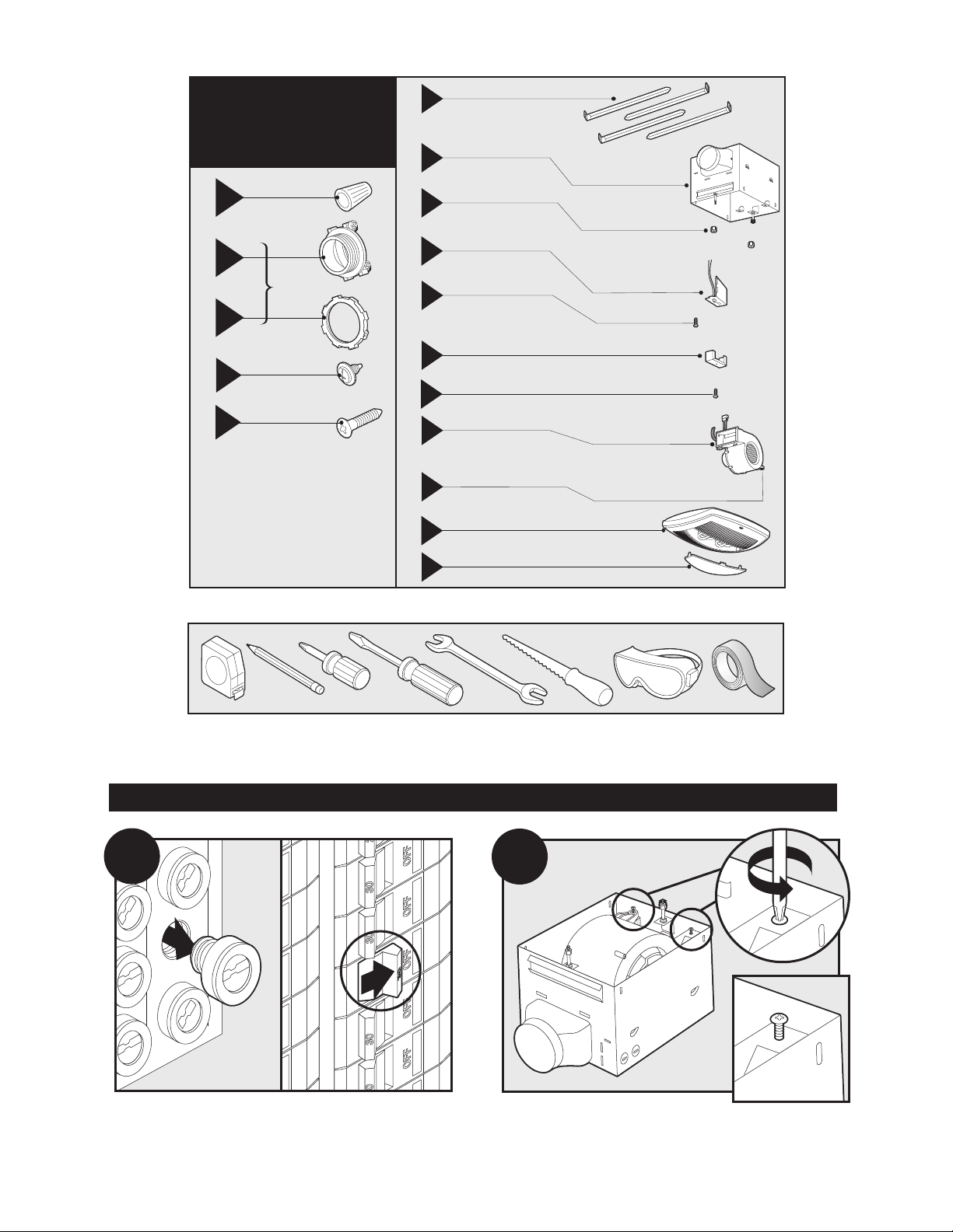
Check all the parts. If damaged, call
1-888-830-1326 for replacement.
x4
E
Mounting Screws
Fa n Mounting Screws
*
NOTE:
Strain relief (not supplied) cable
connector must be installed.
Attachment Screws
97932-01-262
97118-03-000
97118-04-000
J
Strain Relief Bracket
K
Strain Relief Bracket Screw
65872-01-000
74508-53
H
75184-01-133
Light Fixture Thumbnuts
O
x2
Lens
87259-01-000
P
95044-01-000
Mounting Rails
A
B
Before Installation
Estimated assembly time: 30 to 60 minutes
Included.
Tools Needed. (Not supplied.)
Turn off the power source.
42936-01 10/17/2007
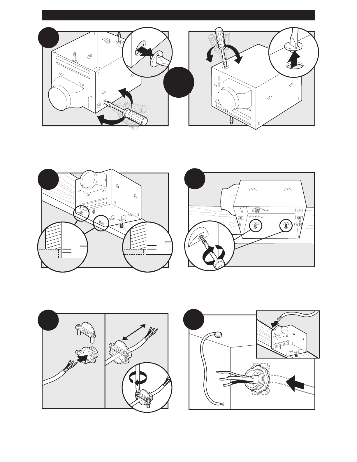
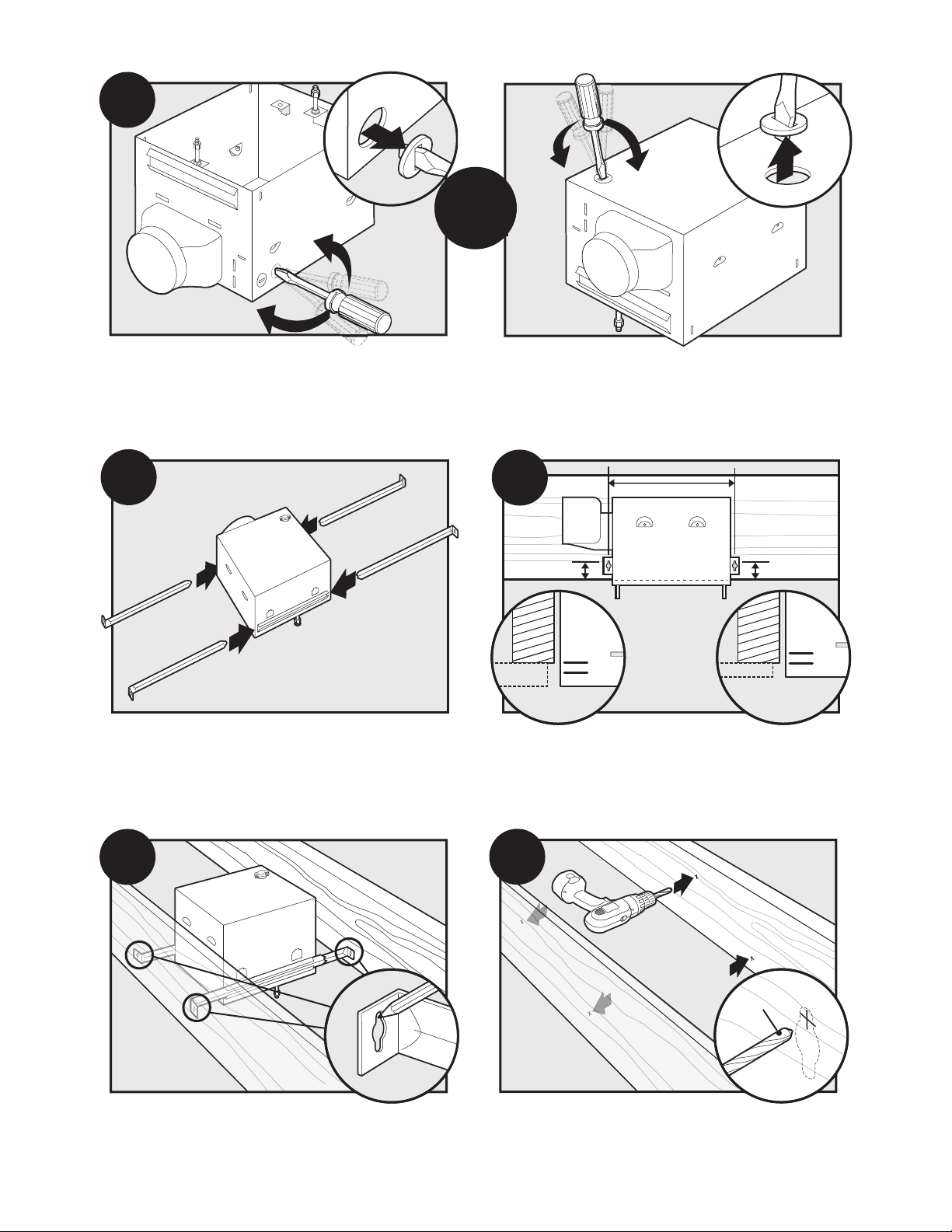
Loosen the fan mounting screws.
4
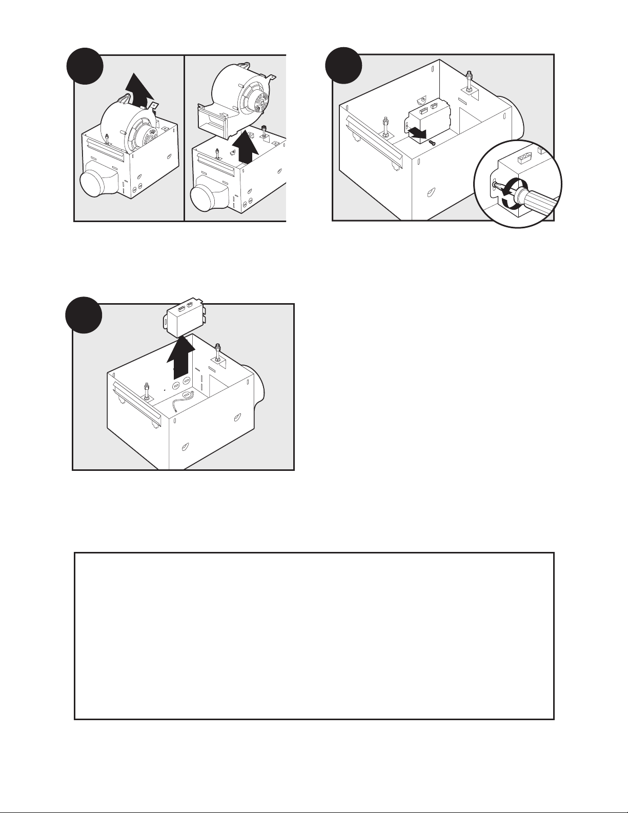
Remove the fan assembly from the housing.
D
E
C
Remove the wiring cover.
Loosen the wiring cover screw.
Choose Installation Option
For New Construction - attaching to joist, go to step A1, page 5.
For New Construction - suspended between, joists go to step B1, page 7.
For Existing Construction - accessible from above, go to step C1, page 9.
For Existing Construction - accessible only from below, go to step D1, page 12.
5
42936-01 10/17/2007
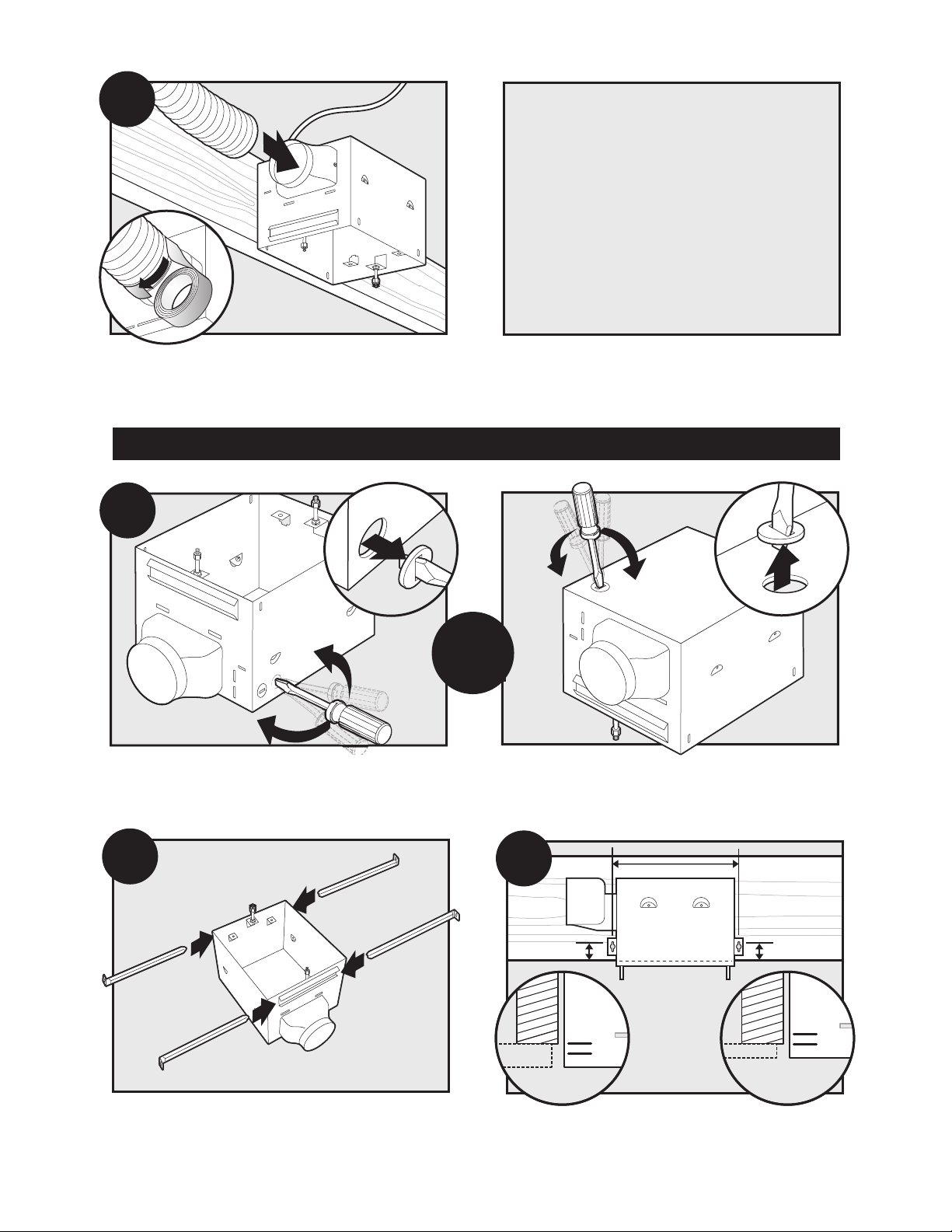
A1
Section A - New Construction - attaching to joist
5/8
1/2
5/8
1/2
A2
A5
A3
3”
A4
OR
Pop out a wiring access slug.
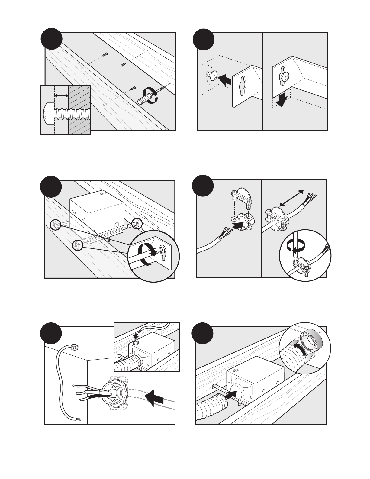
the joist based upon the the thickness of your sheetrock.
Run the power supply wire through the strain relief, leav-
ing 3” between the end of the wire and the strain relief.
42936-01 10/17/2007
Tighten the strain relief around the wire.
Drive mounting screws (supplied) into joist or framing.Position the correct depth mark at the bottom edge of
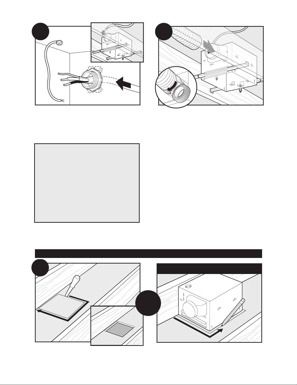
Install the wiring and the strain relief into the wiring
access hole you made earlier.
6
A6
Connect 4” duct and vent to the outside. Use duct tape to
Go to
Section E -
Final Installation
on page 14.
B1
5/8
1/2
5/8
1/2
B3
B2
secure joints. If ducting does not fit securely, an adapter
may need to be purchased.
Section B - New Construction – suspended between joists
OR
Pop out a wiring access slug.
Slide the mounting rails into brackets. Note the orienta-
tion of of the outer ends of the rails.
Position the correct depth mark at the bottom edge of
the joist based upon the the thickness of your sheetrock.
7
42936-01 10/17/2007
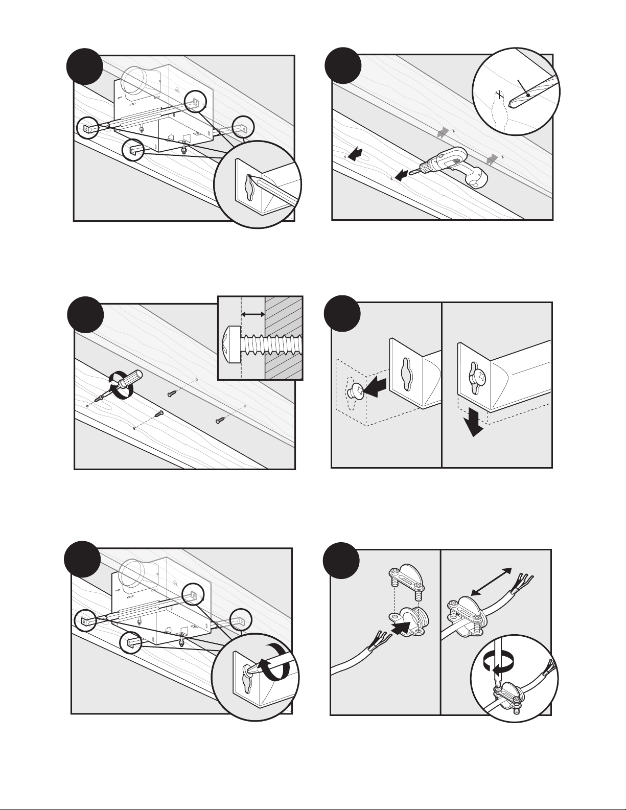
Mark position of screws by using holes as a template.
B4
1/16” bit
B5
B6
B7
B8
3”
B9
Drill a pilot hole at the TOP of each outline.
Insert mounting screws, leaving space between the
screw head and the joist. (Screws are supplied.)
Tighten screws.
42936-01 10/17/2007
Attach the rails onto the screws.
Run the power supply wire through the strain relief, leav-
ing 3” between the end of the wire and the strain relief.
Tighten the strain relief around the wire.
8
B10
Install the wiring and the strain relief into the wiring
B11
Go to
Section E -
Final Installation
on page 14.
NO EXISTING FAN
access hole you made earlier.
Connect 4” duct and vent to the outside. Use duct tape to
secure joints. If ducting does not fit securely, an adapter
may need to be purchased.
Section C - Existing Construction – accessible from above
Remove an existing fan and check to make sure the
opening is large enough to accommodate the new fan
housing. The opening needs to be 11” x 9 5/8”.
OR
9
42936-01 10/17/2007
C3
5/8
1/2
5/8
1/2
C4
Pop out a wiring access slug.
1/16” bit
C6
C5
C3
OR
Slide the mounting rails into brackets.
Mark position of screws by using holes as a template.
42936-01 10/17/2007
Using the depth markings on the housing, position the
bottom edge of the housing so that it will be flush with
the sheetrock.
Drill a pilot hole at the TOP of each outline, AS SHOWN.
10
C7
Insert mounting screws, leaving space between the
C8
C9
3”
C10
C11
C12
screw head and the joist. (Screws are supplied.)
Attach the rails onto the screws.
Tighten screws.
Install the wiring and the strain relief into the wiring
access hole you made earlier.
Run the power supply wire through the strain relief, leav-
ing 3” between the end of the wire and the strain relief.
Tighten the strain relief around the wire.
Connect 4” duct and vent to the outside. Use duct tape to
secure joints. If ducting does not fit securely, an adapter
may need to be purchased.
11
42936-01 10/17/2007
 Loading...