

Model: 50144 Matte Black
50145 Fresh White
52068 Provencal Gold
52069 Antique Pewter
Fan weight ±2 lbs: 18.7 lbs (8.5 kg)
Low Prole
Installation Manual
©2019 Hunter Fan Co.
PG3833 r110119
1886
Congratulations on purchasing your new Hunter® ceiling fan!
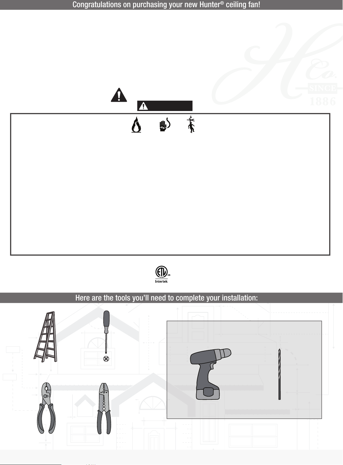
Here are the tools you’ll need to complete your installation:
The ceiling fan you purchased will provide comfort and performance in your home or ofce for many years. This instruction manual contains
WARNING
complete instructions for installing and operating your fan. We are proud of our work and appreciate the opportunity to supply you with the
best ceiling fan available anywhere in the world.
We are here to help!
This Instruction Manual is designed to make installation as simple as possible. While working through this Instruction Manual, keep
your smartphone or tablet nearby. We have added video links to help you through the more technical sections. If you are unfamiliar or
uncomfortable with wiring, contact a qualied electrician. We also provide telephone support at 1.888.830.1326 or visit us
at HunterFan.com.
READ and SAVE These Instructions
Warning
w.1 - To reduce the risk of re, electrical shock, or personal injury, mount fan directly from building structure and/or an outlet box marked acceptable for fan support of 70 lbs (31.8 kg) and use the
mounting screws provided with the outlet box.
w.2 - To avoid possible electrical shock, before installing or servicing your fan, disconnect the power by turning off the circuit breakers to the outlet box and associated wall switch location. If you
cannot lock the circuit breakers in the off position, securely fasten a prominent warning device, such as a tag, to the service panel.
w.3 – To reduce the risk of electric shock, this fan must be installed with an isolating wall control/switch.
w.4 - To reduce the risk of personal injury, do not bend the blade brackets when installing the blade brackets, balancing the blades, or cleaning the fan. Do not insert foreign objects in between
rotating fan blades.
Caution
c.1 - All wiring must be in accordance with national and local electrical codes ANSI/NFPA 70. If you are unfamiliar with wiring, use a qualied electrician.
c.2 - Use only Hunter replacement parts.
This equipment has been tested and found to comply with the limits for a Class B digital device, pursuant to part 15 of the FCC Rules. These limits are designed to provide reasonable protection
against harmful interference in a residential installation. This equipment generates, uses and can radiate radio frequency energy and if not installed and used in accordance with the instructions
may cause harmful interference to radio communications.
However, there is no guarantee that interference will not occur in a particular installation. If this equipment does cause harmful interference to radio or television reception, which can be
determined by turning the equipment off and on, the user is encouraged to try to correct the interference by one or more of the following measures:
• Reorient or relocate the receiving antenna.
• Increase the separation between the equipment and receiver.
• Connect the equipment into an outlet on a circuit different from that to which the receiver is connected.
• Consult the dealer or an experienced radio/TV technician for help.
Caution: modications not approved by the party responsible for compliance could void user’s authority to operate the equipment.
This device complies with Part 15 of the FCC Rules. Operation is subject to the following two conditions: (1) This device may not cause harmful interference, and (2) this device must accept any
interference received, including interference that may cause undesired operation.
Ladder
This product conforms to UL Standard 507.
OPTIONAL
If mounting to a support structure, you will also need these tools.
Screwdriver
9/64” Drill BitDrill
Pliers
1
© 2019 Hunter Fan Company
7130 Goodlett Farms Pkwy, Suite 400
Wire Strippers
Memphis TN 38016
1886
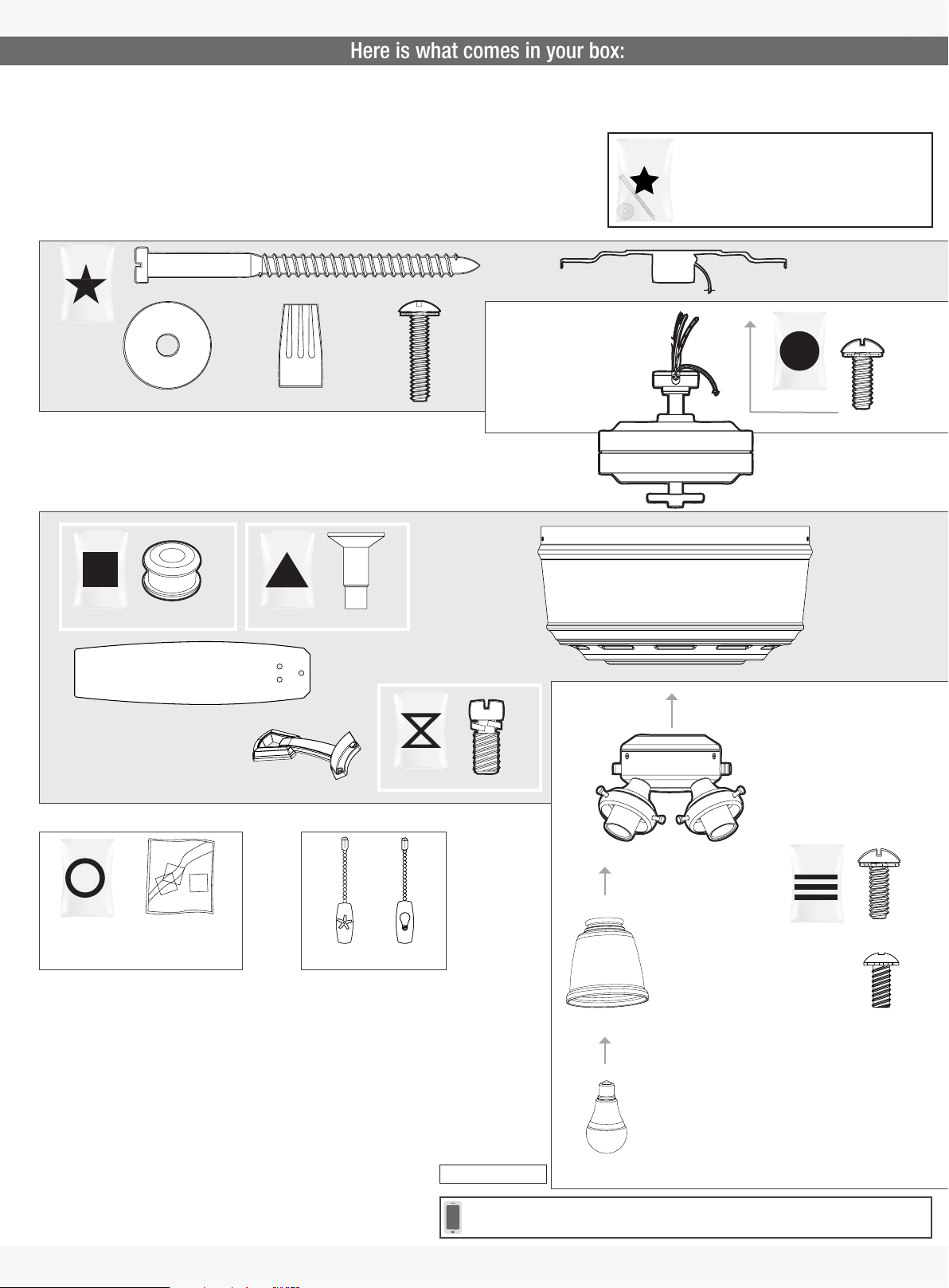
We recommend that you pull everything out of the box and lay it out. We have
Here is what comes in your box:
grouped the drawn components below with the hardware you’ll need for those
parts. The screws below are drawn to scale to make it easier to identify what
piece of hardware is needed to install each component.
Hunter Pro Tip:
Do not discard the hardware bags or mix parts from
different bags. Make note of the symbol printed on
each hardware bag. The symbols can be used to
identify the appropriate hardware for each step.
bag
Washer
x2
For installing the hanger bracket and wiring the fan
bag bag
For installing the blades
Grommet
Blade
x15 x15
x5
Blade Arm
Wire Nut
x4
Blade Screw
x5
bag
x2
Wood Screw
Locking
Screw
x2
Blade Arm Screw
x10
Ceiling Bracket
bag
For installing the housing
Motor
Motor Housing
Upper Switch Housing
Lower Switch Housing
Motor Housing
Screw
x4
bag
For your convenience,
you may receive extra fasteners. Pullchains
M0215-01 r103119
Spare Parts
Note:
Fan style may vary.
Find a part that is missing or damaged?
Don’t take it back to the store. Let us make it right. Visit us at HunterFan.com or call us at 1.888.830.1326.
Bulb
x3
Glass
x3
x3
bag
Light Kit Screw
x3
Switch Housing
Screw
For installing the light xture
2
 Loading...