

Page 1

Owner’s Manual with Installation Directions Model 44428
© 1995, HUNTER FAN COMPANY FORM NO. 41213-6/95
Programmable Thermostat For Single
and Multistage Heat Pump Systems
Auto Temp II Heat Pump
TM
Hunter Fan Company • 2500 Frisco Avenue • Memphis, TN 38114
Page 2
2
Table of Contents
Congratulations!
Welcome to the Hunter energy saving family of quality
products.
Your Hunter Programmable Thermostat allows you to find
your maximum comfort level using the least amount of
fuel. Through smart programming, this thermostat should
pay for itself during its first season of use.
Thank you for buying Hunter products!
Features 2
Start Up 3
Keyboard Lock Feature 5
Setting The Time/Day Of The Week 6
Personal Program Schedule 7
Programming 8
Displaying Programs 11
To Review The Current Temperature Setting 12
Manual Overrides 13
Using The Energy Monitor Usage Review 14
Temperature Span 15
Energy Usage Chart 16
Different Operation Modes 17
Trouble Shooting 18
Installing Thermostat 19
Remove Old Thermostat 20
Label Wires 20
Mount Wallplate and Thermostat 21
Connect Wires and Mount Thermostat Cover to Wall Plate 22
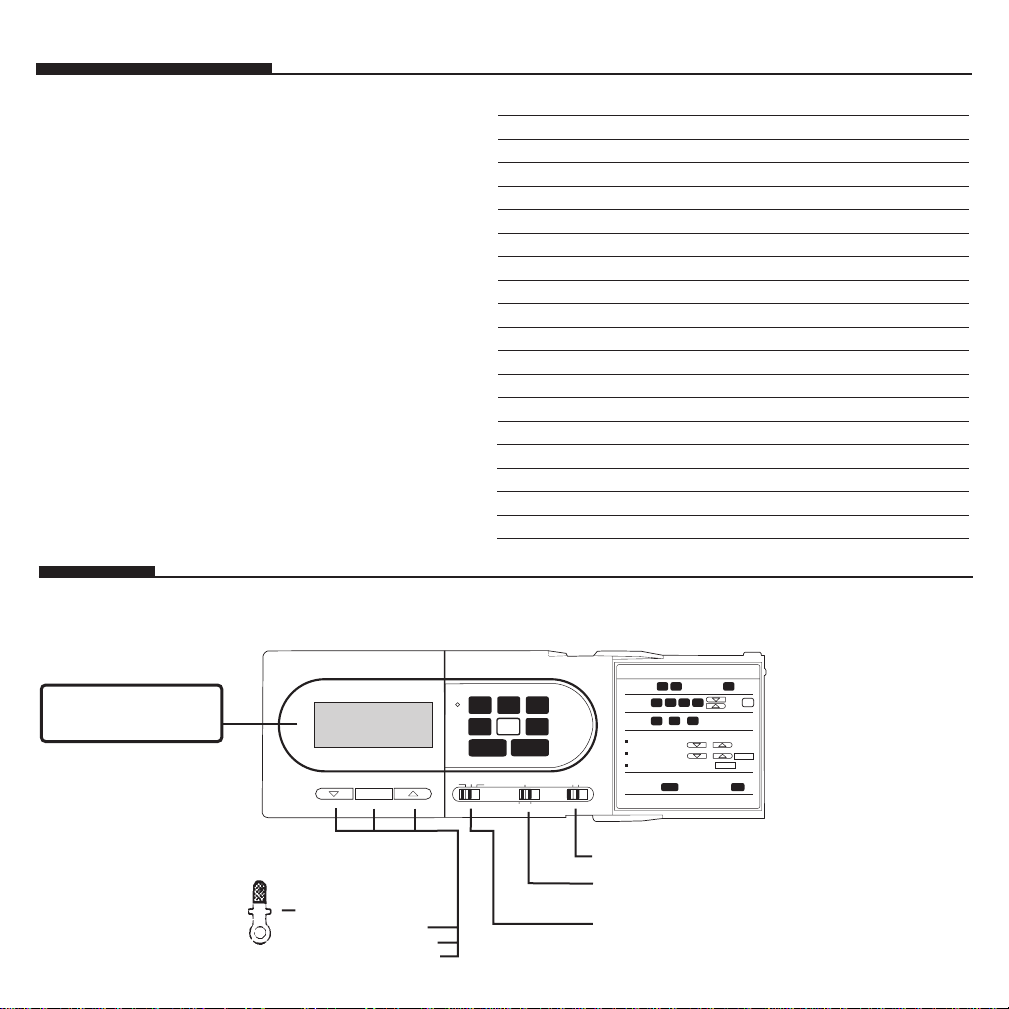
Features
HOLD CLEAR
HOLD CLEAR
or
or
HOLD CLEAR
To set day:
To set time:
To set
programs
To review
programs
Press for Today
and Yesterday
Replace batteries when "Low Batt" indicator appears
Next
Prog
To overide programmed temperatures (press for 3 seconds):
To display energy usage:
Temporary change until next
program:
Constant hold until manually
cleared:
Return to regular programmed temperature:
MODEL: 44428
Auto Temp II Heat Pump
RESET
NORMAL
OFF
A/C
HEAT AUTO
FAN
HEAT RECOVERY
EMERG. HEAT
HOUR
AUX
USAGE
PROG
DAY
MIN
PROG
DAY
USAGE
RETURN
HOUR DAYMIN
HOUR MIN
PROG
DAY
AUX
USAGE
PROG
DAY
PROG
PROG
USAGE
PROG
PROG
For Total
Aux Usage Press
ROOM TEMP
AM
MO
12:38
75
■ Exclusive Energy Monitor
Measures and displays the amount
of time the heating or air-conditioning system has operated today and
yesterday. By programming your
thermostat and monitoring the energy usage, you can save 9% to 30%
on your fuel bills.
■ Low Battery Indicator
“LOW BATT” flashes when its time
to change the batteries.
■
Fingertip Programming
Easy touch keyboard. Keys
“beep” when pressed.
■
Manual Override and
Compressor Safety Delay
Compressor safety restart
“Delay” appears on display.
■
Vacation Override
Provides permanent (vacation)
temperature setting without
program change.
■
Manual Override
For either temporary or
constant temperature
adjustments without program
change.
■
Fan ON and AUTO Selector switch.
■
Normal, Heat Recovery and
Emergency Heat Switch
■
Function Switch
Switch for turning on heat and
cooling systems.
■
Key Hole for Keyboard Lock
You can prevent tampering of
programs by selecting
keyboard lock feature.
■
Key to lock keyboard.
■
For raising temperature.
■
For lowering temperature.
■
Manual override hold clear
button.
■
Convenient Programming
Reference
Simplified programming
instructions are provided on
inside of door cover for easy
reference.
■ Easy-to-Read Digital Display
Digital clock (liquid crystal display)
indicates time of day AM or PM, day
of week, current room temperature,
current program number, LO BATT
indicator, heat and cool indicator
when heat or cool is on, and usage
indicator.
MO TU WE TH FR SA SU LOW BATT
PROG# 1 2 3 4 SET TEMP HOLD ROOM TEMP
EMERG AUX HEAT COOL USAGE DELAY AUTO-RECOVERY
PM
I8:88 88
AM
UNTIL
NEXT
PROG
Page 3
Don’t Worry—Programming Is Easy!
Start Up
This may seem to be a highly comprehensive and lengthy presentation of our product's features—don’t be intimidated.
We have a lot to say because our product does have a lot of features. And we want to make sure you have complete information. You
may find you'll want to use only a simple program…or all the features
we have to offer.
Just follow this manual one step at a time and you should quickly
begin to feel comfortable with your new thermostat.
Besides, we’ve installed preset programs at 78° for air conditioning
and 68° for heating. These programs are up and running immediately at installation. In case you don’t have time to enter your own
programs right away.
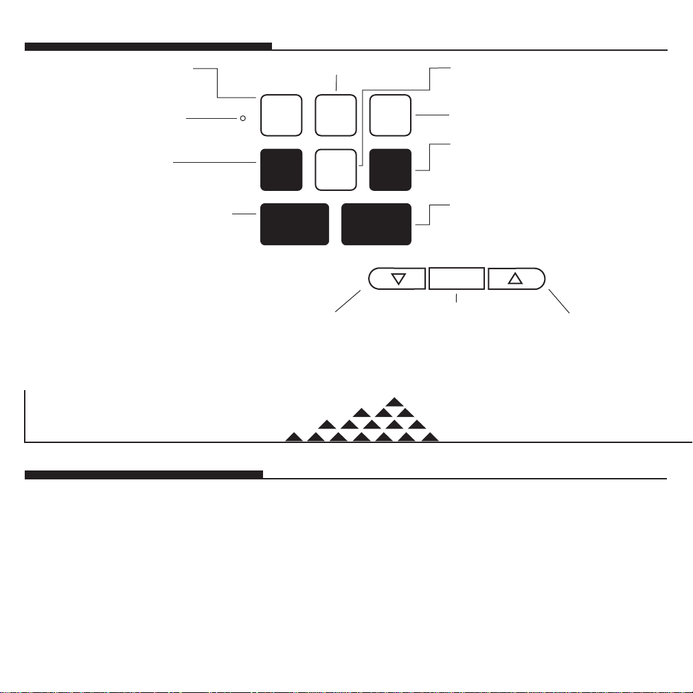
For entering minute of day.
Day selection key for
selecting weekdays,
weekends or individual
day for programming.
For entering and reviewing
programs.
For entering current day of week.
Displays cumulative usage of
auxiliary heat in hours and minutes.
Returns to current time
and temperature.
For entering hour of day.
For resetting computer
back to factory program
and clock to 12:00 am.
Key to lower
temperature
setting
HOUR
MIN DAY
PROG
USAGE
RETURN
PROG
DAY
AUX
USAGE
3
Energy Monitor key recalls energy
usage today and yesterday.
LCD shows energy usage in hours
and minutes.
RESET
HOLD
CLEAR
Key to raise
temperature
setting
Provides constant temperature setting
by overriding stored programs, or
converts to manual operation of thermostat. Also clears manual override
to return to current program.
Keyboard Quick Reference
Page 4

You can generate significant savings with a programmable thermostat. The idea is to reduce usage when you don’t need it—when
you’re not home or at night while everyone’s asleep. For example,
during the heating season you can program lower temperatures during the day while you’re at work. Then program a comfortable temperature just before you get home, so you walk into a warm house.
Studies conducted by the Department of Energy estimate that setting
your thermostat back 10° for two-8 hour periods on winter days can
reduce your fuel bill as much as 30%. During the summer, setting
your thermostat up 5° for two periods can reduce your fuel bill as
much as 25%.
And the digital display on your thermostat gives you precise temperature control for convenience as well as maximum savings and
comfort.
The thermostat is truly 7 day programmable and can hold separate
programs for winter and summer. It is capable of holding 4 separate
heat and 4 separate programs for cool, each day.
You can program Monday to Friday, Saturday and Sunday to have
the same 4 programs as shown in the table or each day can have a
different set of 4 programs. (4 for winter and 4 for summer).
Suggested winter and summer weekday and weekend programs are
shown below.
Suggested Winter & Summer Programs
Winter Summer
Temperature Temperature
Mon.-Fri. Time Settings Settings
Program 1 6:00 AM 68° 78°
Program 2 8:30 AM 60° 84°
Program 3 5:00 PM 68° 78°
Program 4 11:00 PM 58° 80°
Page 5
5
Keyboard Lock Feature
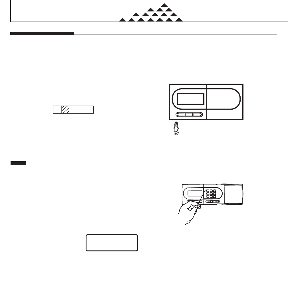
Your thermostat is provided with an optional electronic keyboard lock.
You may use this feature to prevent tampering with the programs.
The keyboard can be made active by using the key provided with
your thermostat.
If you elect to use this feature, remove the cover from the thermostat
and look for the switch shown below on the printed circuit board near
the key hole. Be careful not to disconnect any wires. Then slide the
keyboard switch to “lock” mode.
Once the switch is moved to “lock” mode, no entry is possible by the
thermostat keys. Even the manual override is not possible. To activate the keyboard (open lock) for changing programs or setting new
time, insert the key in the key hole. After programming is completed,
remove the key to lock the keyboard again.
If the keyboard selector switch is in “unlock” mode, there is no need
to use key. Programs can be changed any time without using the key.
Keyboard Lock Switch
Unlock Lock
Figure 1
Reset
When you first install the three AAsize batteries, as directed in the Installation Instructions, the thermostat automatically sets the day and time to
Monday, 12:00 AM, shows the current room temperature and is programmed for 68° in heat mode and 78° in cool mode for all 7 days.
Press the reset button to reset and start the clock. Use a thin probe such as a
straightened paper clip to gently push the reset button through the hole in the front
panel. (See Figure 3.) The LCD display should read 12:00 AM, indicate the day of
week as Monday (MO), the current room temperature of your house. If it shows random numbers or partial digits, press the reset button once again.
■ Initial read-out after pressing reset button.
■ Current room temperature is 72°F.
■ Day of week is Monday (MO).
■ Time is 12:00 AM.
Insert key here for programming.
Figure 2
Figure 3
MO TU WE TH FR SA SU LOW BATT
PROG# 1 2 3 4 SET TEMP HOLD ROOM TEMP
EMERG AUX HEAT COOL USAGE DELAY AUTO-RECOVERY
PM
I2:00 72
AM
UNTIL
NEXT
PROG
Start Up
Page 6
■ Returns to normal time and temperature.
■ If return is not pressed, it will return automatically in 15 seconds.
6
■ Initial read-out after pressing reset button.
■ Current room temperature is 72°F.
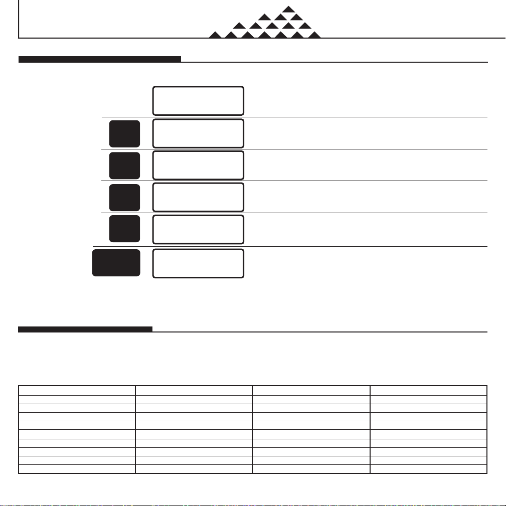
Setting the Time and Day of Week
■ Press the HOUR key. Temperature digits disappear, indicating time
set mode.
■ Press and hold until 9:00 PM appears on display.
■ Press and hold until 15 minutes appears on display.
■ Press 5 times until SA appears on display.
EXAMPLE:
If the unit is being
installed at 9:15
PM, Saturday, to set
the thermostat, you
would press the
keys in the shown
sequence:
Personal Program Schedule
Use this Personal 7 Day Program Schedule to determine which times
and temperatures will best satisfy both your comfort and energy
saving requirements. This will also be a helpful guide as you start
programming your thermostat.
PROGRAM SELECTION TABLE
SAVE FOR FUTURE REFERENCE
MONDAY TIME WINTER TEMP SUMMER TEMP
Program 1
Program 2
Program 3
Program 4
TUESDAY TIME WINTER TEMP SUMMER TEMP
Program 1
Program 2
Program 3
Program 4
MO TU WE TH FR SA SU LOW BATT
PROG# 1 2 3 4 SET TEMP HOLD ROOM TEMP
EMERG AUX HEAT COOL USAGE DELAY AUTO-RECOVERY
PM
I2:00 72
AM
UNTIL
NEXT
PROG
MO TU WE TH FR SA SU LOW BATT
PROG# 1 2 3 4 SET TEMP HOLD ROOM TEMP
EMERG AUX HEAT COOL USAGE DELAY AUTO-RECOVERY
PM
I2:00 72
AM
UNTIL
NEXT
PROG
MO TU WE TH FR SA SU LOW BATT
PROG# 1 2 3 4 SET TEMP HOLD ROOM TEMP
EMERG AUX HEAT COOL USAGE DELAY AUTO-RECOVERY
PM
I9:00 72
AM
UNTIL
NEXT
PROG
MO TU WE TH FR SA SU LOW BATT
PROG# 1 2 3 4 SET TEMP HOLD ROOM TEMP
EMERG AUX HEAT COOL USAGE DELAY AUTO-RECOVERY
PM
I9:!5 72
AM
UNTIL
NEXT
PROG
MO TU WE TH FR SA SU LOW BATT
PROG# 1 2 3 4 SET TEMP HOLD ROOM TEMP
EMERG AUX HEAT COOL USAGE DELAY AUTO-RECOVERY
PM
I9:!5 72
AM
UNTIL
NEXT
PROG
MO TU WE TH FR SA SU LOW BATT
PROG# 1 2 3 4 SET TEMP HOLD ROOM TEMP
EMERG AUX HEAT COOL USAGE DELAY AUTO-RECOVERY
PM
I9:!5 72
AM
UNTIL
NEXT
PROG
HOUR
HOUR
MIN
DAY
RETUR
N
Start Up
The first data you should enter is the current time and day of the week.
Page 7

WEDNESDAY TIME WINTER TEMP SUMMER TEMP
Program 1
Program 2
Program 3
Program 4
THURSDAY TIME WINTER TEMP SUMMER TEMP
Program 1
Program 2
Program 3
Program 4
FRIDAY TIME WINTER TEMP SUMMER TEMP
Program 1
Program 2
Program 3
Program 4
SATURDAY TIME WINTER TEMP SUMMER TEMP
Program 1
Program 2
Program 3
Program 4
SUNDAY TIME WINTER TEMP SUMMER TEMP
Program 1
Program 2
Program 3
Program 4
7
Before Programming
■ To program for winter, the function switch (OFF-A/C-HEAT) must
be in the HEAT mode.
■ Similarly, to program for summer, the function switch must be in
COOL position.
■ You cannot program or view programs in OFF position.
■ Whenever the compressor is in 4 minute restart safety delay,
“DELAY” will appear on the display. Compressor will turn on
automatically when this 4 minute delay period is over. This feature
is designed to protect your compressor from restarting too quickly
which could damage the compressor.
■ Replace batteries as soon as low battery indicator appears on the
display.
CAUTION: When the batteries are completely dead, the display
will fade out and the thermostat will not switch
“ON” your system.
SAVE FOR FUTURE REFERENCE
Start Up
Page 8

8
■ Program Indicator (2) is displayed.
■ 0:00 space for time of second program is displayed.
■ Program Indicator (3) is displayed.
■ Press and hold until 8:00 AM is displayed.
■ Clock advances in increments of 15 minutes. Press each time until
30 minutes is displayed.
■ Press DOWN ARROW until 60°F is displayed.
Programming
Familiarize yourself with programming. In this example, your thermostat will be programmed for winter as per suggested program on page 4.
However, you can program or change the program of each individual day.
■ Press and hold until 6:00 AM is displayed.
■ Weekday Program 1 is complete.
■ Program indicator (1) is displayed.
■ 68°F is displayed.
■ 0:00 space for time is displayed.
■ MO-FR is displayed.
■ Normal display of time, temperature, and day of week.
■ Weekdays are selected.
Weekday
Programs
Note: During the programming steps, if you don’t make any entry within 15 seconds, the display will automatically return to current t ime and temperature. If this
happens, just press the “PROGRAM” key to return to the program number you were entering.
To Program For
Winter, Slide
Function Switch
To HEAT.
HOUR
HOUR
MIN
PROG
PROG
PROG
MO TU WE TH FR SA SU LOW BATT
PROG# 1 2 3 4 SET TEMP HOLD ROOM TEMP
EMERG AUX HEAT COOL USAGE DELAY AUTO-RECOVERY
PM
I6:00 68
AM
UNTIL
NEXT
PROG
MO TU WE TH FR SA SU LOW BATT
PROG# 1 2 3 4 SET TEMP HOLD ROOM TEMP
EMERG AUX HEAT COOL USAGE DELAY AUTO-RECOVERY
PM
I0:00 68
AM
UNTIL
NEXT
PROG
MO TU WE TH FR SA SU LOW BATT
PROG# 1 2 3 4 SET TEMP HOLD ROOM TEMP
EMERG AUX HEAT COOL USAGE DELAY AUTO-RECOVERY
PM
I8:00 68
AM
UNTIL
NEXT
PROG
MO TU WE TH FR SA SU LOW BATT
PROG# 1 2 3 4 SET TEMP HOLD ROOM TEMP
EMERG AUX HEAT COOL USAGE DELAY AUTO-RECOVERY
PM
I8:30 68
AM
UNTIL
NEXT
PROG
MO TU WE TH FR SA SU LOW BATT
PROG# 1 2 3 4 SET TEMP HOLD ROOM TEMP
EMERG AUX HEAT COOL USAGE DELAY AUTO-RECOVERY
PM
I8:30 60
AM
UNTIL
NEXT
PROG
MO TU WE TH FR SA SU LOW BATT
PROG# 1 2 3 4 SET TEMP HOLD ROOM TEMP
EMERG AUX HEAT COOL USAGE DELAY AUTO-RECOVERY
PM
I0:00 68
AM
UNTIL
NEXT
PROG
MO TU WE TH FR SA SU LOW BATT
PROG# 1 2 3 4 SET TEMP HOLD ROOM TEMP
EMERG AUX HEAT COOL USAGE DELAY AUTO-RECOVERY
PM
I9:!5 72
AM
UNTIL
NEXT
PROG
MO TU WE TH FR SA SU LOW BATT
PROG# 1 2 3 4 SET TEMP HOLD ROOM TEMP
EMERG AUX HEAT COOL USAGE DELAY AUTO-RECOVERY
PM
I2:00 72
AM
UNTIL
NEXT
PROG
MO TU WE TH FR SA SU LOW BATT
PROG# 1 2 3 4 SET TEMP HOLD ROOM TEMP
EMERG AUX HEAT COOL USAGE DELAY AUTO-RECOVERY
PM
I0:00 68
AM
PROG
DAY
Programming
Page 9

■ Program Indicator (4) is displayed.
■ Program indicator (2) is displayed.
■ Press and hold until 7:00 AM is displayed.
■ Saturday and Sunday Program is now complete.
■ Press the DOWN ARROW until 60°F is displayed.
■ SA and SU is displayed.
■ Program indicator (1) is displayed.
9
■ SA and SU are selected.
■ Press and hold until 5:00 PM is displayed.
■ Weekday Program 3 is complete.
■ Press and hold until 11:00 PM is displayed.
■ Press and hold until 8:00 AM is displayed.
■ Clock advances in increments of 15 minutes. Press and hold until 30
minutes is displayed.
■ Press the DOWN ARROW until 60°F is displayed.
PROG
PROG
PROG
DAY
HOUR
HOUR
HOUR
MIN
HOUR
MO TU WE TH FR SA SU LOW BATT
PROG# 1 2 3 4 SET TEMP HOLD ROOM TEMP
EMERG AUX HEAT COOL USAGE DELAY AUTO-RECOVERY
PM
I5:00 68
AM
UNTIL
NEXT
PROG
MO TU WE TH FR SA SU LOW BATT
PROG# 1 2 3 4 SET TEMP HOLD ROOM TEMP
EMERG AUX HEAT COOL USAGE DELAY AUTO-RECOVERY
PM
I0:00 68
AM
UNTIL
NEXT
PROG
MO TU WE TH FR SA SU LOW BATT
PROG# 1 2 3 4 SET TEMP HOLD ROOM TEMP
EMERG AUX HEAT COOL USAGE DELAY AUTO-RECOVERY
PM
!!:00 68
AM
UNTIL
NEXT
PROG
MO TU WE TH FR SA SU LOW BATT
PROG# 1 2 3 4 SET TEMP HOLD ROOM TEMP
EMERG AUX HEAT COOL USAGE DELAY AUTO-RECOVERY
PM
!!:00 60
AM
UNTIL
NEXT
PROG
MO TU WE TH FR SA SU LOW BATT
PROG# 1 2 3 4 SET TEMP HOLD ROOM TEMP
EMERG AUX HEAT COOL USAGE DELAY AUTO-RECOVERY
PM
!0:00 68
AM
UNTIL
NEXT
PROG
MO TU WE TH FR SA SU LOW BATT
PROG# 1 2 3 4 SET TEMP HOLD ROOM TEMP
EMERG AUX HEAT COOL USAGE DELAY AUTO-RECOVERY
PM
!7:00 68
AM
UNTIL
NEXT
PROG
MO TU WE TH FR SA SU LOW BATT
PROG# 1 2 3 4 SET TEMP HOLD ROOM TEMP
EMERG AUX HEAT COOL USAGE DELAY AUTO-RECOVERY
PM
!0:00 68
AM
UNTIL
NEXT
PROG
MO TU WE TH FR SA SU LOW BATT
PROG# 1 2 3 4 SET TEMP HOLD ROOM TEMP
EMERG AUX HEAT COOL USAGE DELAY AUTO-RECOVERY
PM
!8:00 68
AM
UNTIL
NEXT
PROG
MO TU WE TH FR SA SU LOW BATT
PROG# 1 2 3 4 SET TEMP HOLD ROOM TEMP
EMERG AUX HEAT COOL USAGE DELAY AUTO-RECOVERY
PM
!8:30 68
AM
UNTIL
NEXT
PROG
MO TU WE TH FR SA SU LOW BATT
PROG# 1 2 3 4 SET TEMP HOLD ROOM TEMP
EMERG AUX HEAT COOL USAGE DELAY AUTO-RECOVERY
PM
!8:30 60
AM
UNTIL
NEXT
PROG
MO TU WE TH FR SA SU LOW BATT
PROG# 1 2 3 4 SET TEMP HOLD ROOM TEMP
EMERG AUX HEAT COOL USAGE DELAY AUTO-RECOVERY
PM
!!:00 60
AM
UNTIL
NEXT
PROG
Programming
Programming Your Thermostat (Cont.)
Page 10

Programming
■ Only Monday is selected.
■ Program indicator (4) is displayed.
10
Programming Your Thermostat (Cont.)
■ Press to return to display current time, temperature, current program
number, and day of week. If it is not pressed, thermostat will
automatically return to current time and temperature in 15 seconds.
■ Program indicator (3) is displayed.
■ Press and hold until 4:00 PM is displayed.
■ Press and hold until 11:00 PM is displayed.
■ Press DOWN ARROW each time to decrease one degree.
■ When you reach 58°F, Program 4 is complete.
To program each individual day separately by a different set of programs, first select the day by displaying the day of program, then insert the
desired times and temperatures.
■ SA and SU will have same program.
■ MO-FR will have same program.
PROG
DAY
PROG
DAY
PROG
DAY
PROG
PROG
RETUR
N
MO TU WE TH FR SA SU LOW BATT
PROG# 1 2 3 4 SET TEMP HOLD ROOM TEMP
EMERG AUX HEAT COOL USAGE DELAY AUTO-RECOVERY
PM
I0:00 68
AM
UNTIL
NEXT
PROG
MO TU WE TH FR SA SU LOW BATT
PROG# 1 2 3 4 SET TEMP HOLD ROOM TEMP
EMERG AUX HEAT COOL USAGE DELAY AUTO-RECOVERY
PM
I4:00 68
AM
UNTIL
NEXT
PROG
MO TU WE TH FR SA SU LOW BATT
PROG# 1 2 3 4 SET TEMP HOLD ROOM TEMP
EMERG AUX HEAT COOL USAGE DELAY AUTO-RECOVERY
PM
I0:00 68
AM
UNTIL
NEXT
PROG
MO TU WE TH FR SA SU LOW BATT
PROG# 1 2 3 4 SET TEMP HOLD ROOM TEMP
EMERG AUX HEAT COOL USAGE DELAY AUTO-RECOVERY
PM
II:00 68
AM
UNTIL
NEXT
PROG
MO TU WE TH FR SA SU LOW BATT
PROG# 1 2 3 4 SET TEMP HOLD ROOM TEMP
EMERG AUX HEAT COOL USAGE DELAY AUTO-RECOVERY
PM
I!:00 68
AM
UNTIL
NEXT
PROG
MO TU WE TH FR SA SU LOW BATT
PROG# 1 2 3 4 SET TEMP HOLD ROOM TEMP
EMERG AUX HEAT COOL USAGE DELAY AUTO-RECOVERY
PM
I!:00 68
AM
UNTIL
NEXT
PROG
MO TU WE TH FR SA SU LOW BATT
PROG# 1 2 3 4 SET TEMP HOLD ROOM TEMP
EMERG AUX HEAT COOL USAGE DELAY AUTO-RECOVERY
PM
I!:00 68
AM
UNTIL
NEXT
PROG
MO TU WE TH FR SA SU LOW BATT
PROG# 1 2 3 4 SET TEMP HOLD ROOM TEMP
EMERG AUX HEAT COOL USAGE DELAY AUTO-RECOVERY
PM
I!:00 58
AM
UNTIL
NEXT
PROG
MO TU WE TH FR SA SU LOW BATT
PROG# 1 2 3 4 SET TEMP HOLD ROOM TEMP
EMERG AUX HEAT COOL USAGE DELAY AUTO-RECOVERY
PM
I9:!5 72
AM
UNTIL
NEXT
PROG
HOUR
HOUR
Page 11

Programming
NOTE: Another approach to programming is to first program all weekdays or weekends the same, then display a particular day
and change the programs of only that individual day by using
NOTICE: During the programming steps, if you don‘t make an entry within 15 seconds, the display will automatically return to current time
and temperature. If this happens, just press the “PROGRAM” key to return to the program number you were entering.
11
Display the day to be programmed and use to enter programs.
Use to enter programs for Monday.
■ Wednesday is selected.
■ Tuesday is selected.
Displaying Programs
■ Normal display of time, temperature, and day of week.
• To program for summer, slide function switch OFF-A/C-HEAT to
A/C. The programming is the same as you did for winter.
• Any change of time will be effective for both summer and winter. If
your summer schedule is different, however, just revise the program.
• If program time is left at 0:00, that particular program will not be
effective; e.g.
• If Program #2 has time 0:00, the thermostat will jump from Program
#1 to Program #3.
To review programs for winter,
slide function switch to HEAT.
HOUR MIN
PROG
HOUR MIN
PROG
HOUR MIN
PROG
PROG
DAY
PROG
DAY
PROG
DAY
MO TU WE TH FR SA SU LOW BATT
PROG# 1 2 3 4 SET TEMP HOLD ROOM TEMP
EMERG AUX HEAT COOL USAGE DELAY AUTO-RECOVERY
PM
I2:00 72
AM
UNTIL
NEXT
PROG
MO TU WE TH FR SA SU LOW BATT
PROG# 1 2 3 4 SET TEMP HOLD ROOM TEMP
EMERG AUX HEAT COOL USAGE DELAY AUTO-RECOVERY
PM
I2:00 72
AM
UNTIL
NEXT
PROG
MO TU WE TH FR SA SU LOW BATT
PROG# 1 2 3 4 SET TEMP HOLD ROOM TEMP
EMERG AUX HEAT COOL USAGE DELAY AUTO-RECOVERY
PM
I9:!5 72
AM
UNTIL
NEXT
PROG
Programming Your Thermostat (Cont.)
Page 12

Programming
12
■ 4th Weekday program is displayed.
■ Program indicator (4) appears.
■ Monday through Friday remains.
■ 3rd Weekday program is displayed.
■ Program indicator (3) appears.
■ Monday through Friday remains.
Displaying Programs (Cont.)
■ 1st Weekday Winter program is displayed.
■ Program indicator (1) is displayed.
■ Monday through Friday indicator is displayed.
■ HEAT appears indicating heat program for Winter.
■ 2nd Weekday program is displayed.
■ Program indicator (2) appears.
■ Monday through Friday remains.
PROG
■ 70°F indicates the current setting of the thermostat.
■ 68°F indicates current room temperature.
■ If pressed for more than 2 seconds, you will manually override your
present temperatures to a new setting as explained below.
■ Current time and room temperature.
Press for
2 Seconds
or Less:
To Review the Current Temperature Setting
or
To display programs for summer, slide function switch to A/C and press
Note: If you wish to program the thermostat for an individual day (not the MO-FR or SA-SU programs), first display the particular day by pressing
“PROG DAY” key and then use “PROG” key to display or change programs.
To review programs for summer, slide function switch to A/C.
PROG
PROG
PROG
PROG
MO TU WE TH FR SA SU LOW BATT
PROG# 1 2 3 4 SET TEMP HOLD ROOM TEMP
EMERG AUX HEAT COOL USAGE DELAY AUTO-RECOVERY
PM
I9:!5 68
AM
UNTIL
NEXT
PROG
MO TU WE TH FR SA SU LOW BATT
PROG# 1 2 34 SET TEMP HOLD ROOM TEMP
EMERG AUX HEAT COOL USAGE DELAY AUTO-RECOVERY
PM
I9:70 68
AM
UNTIL
NEXT
PROG
MO TU WE TH FR SA SU LOW BATT
PROG# 1 2 3 4 SET TEMP HOLD ROOM TEMP
EMERG AUX HEAT COOL USAGE DELAY AUTO-RECOVERY
PM
I6:00 68
AM
UNTIL
NEXT
PROG
MO TU WE TH FR SA SU LOW BATT
PROG# 1 2 3 4 SET TEMP HOLD ROOM TEMP
EMERG AUX HEAT COOL USAGE DELAY AUTO-RECOVERY
PM
I8:30 60
AM
UNTIL
NEXT
PROG
MO TU WE TH FR SA SU LOW BATT
PROG# 1 2 3 4 SET TEMP HOLD ROOM TEMP
EMERG AUX HEAT COOL USAGE DELAY AUTO-RECOVERY
PM
I5:00 68
AM
UNTIL
NEXT
PROG
MO TU WE TH FR SA SU LOW BATT
PROG# 1 2 3 4 SET TEMP HOLD ROOM TEMP
EMERG AUX HEAT COOL USAGE DELAY AUTO-RECOVERY
PM
I!:00 60
AM
UNTIL
NEXT
PROG
Page 13

71
.
70
72
.
■ Set the function switch to either “A/C” or “HEAT”, depending on the
season.
■ Press either arrow and hold for 3 seconds or more to achieve
desired temperature setting. (55°F for example)
■ Continue pressing arrow. After 3 seconds, the set temperature will
begin to increase. Release the button at 72°F.
13
■ Press arrow to display current temperature setting.
■ 68°F is the current room temperature.
■ 70°F is the present program (#2) setting.
Manual Override of Program
Temporary Manual Override
(OVERRIDE UNTIL NEXT PROGRAM)
or
In the following example, we are raising the temperature from a program setting of 70°F to a temporary setting of 72°F until the time of the next
program change. You might use this, for example, on a holiday when you don’t want the daytime set-back to take effect.
TO DISPLAY TEMPORARY MANUAL OVERRIDE SETTING YOU JUST ENTERED, PRESS EITHER ARROW FOR LESS
THAN 2 SECONDS.
Sometimes you will want to “override” set programs for a particular occasion, and then return to your normal schedule later, without having to
re-enter all your programs. Here are two ways to do this: “temporary” and “constant.”
Constant Manual Override
(OVERRIDE UNTIL MANUALLY RETURNED TO PROGRAM)
In the event that you want to set one temperature for an extended period, such as vacation, use the constant manual override.
■ Press HOLD/CLEAR to maintain override setting
indefinitely. HOLD will flash on LCD.
■ Program number will disappear.
■ Press to return to display time, temperature, day of week. If it is not
pressed, thermostat will automatically return to display of time,
temperature and day of week in about 15 seconds.
TO DISPLAY CONSTANT MANUAL OVERRIDE SETTING YOU JUST ENTERED, PRESS EITHER ARROW
FOR LESS THAN 2 SECONDS.
MO TU WE TH FR SA SU LOW BATT
PROG# 1 2 34 SET TEMP HOLD ROOM TEMP
EMERG AUX HEAT COOL USAGE DELAY AUTO-RECOVERY
PM
I2:70 68
AM
UNTIL
NEXT
PROG
■ Current time and temperature indicator.
■ Showing temporary manual override is valid until next program.
■ If you do not press RETURN, it will automatically return in 15 seconds.
MO TU WE TH FR SA SU LOW BATT
PROG# 1 2 3 4 SET TEMP HOLD ROOM TEMP
EMERG AUX HEAT COOL USAGE DELAY AUTO-RECOVERY
PM
I9:!5 68
AM
UNTIL
NEXT
PROG
MO TU WE TH FR SA SU LOW BATT
PROG# 1 2 3 4 SET TEMP HOLD ROOM TEMP
EMERG AUX HEAT COOL USAGE DELAY AUTO-RECOVERY
PM
I9:68 72
AM
UNTIL
NEXT
PROG
MO TU WE TH FR SA SU LOW BATT
PROG# 1 2 3 4 SET TEMP HOLD ROOM TEMP
EMERG AUX HEAT COOL USAGE DELAY AUTO-RECOVERY
PM
I9:55 72
AM
UNTIL
NEXT
PROG
MO TU WE TH FR SA SU LOW BATT
PROG# 1 2 3 4 SET TEMP HOLD ROOM TEMP
EMERG AUX HEAT COOL USAGE DELAY AUTO-RECOVERY
PM
I9:!5 72
AM
UNTIL
NEXT
PROG
MO TU WE TH FR SA SU LOW BATT
PROG# 1 2 3 4 SET TEMP HOLD ROOM TEMP
EMERG AUX HEAT COOL USAGE DELAY AUTO-RECOVERY
PM
I2:72 68
AM
UNTIL
NEXT
PROG
RETUR
N
HOLD
CLEAR
RETUR
N
Operations
Page 14

■ Resets all usage digits to zero.
MO TU WE TH FR SA SU LOW BATT
PROG# 1 2 3 4 SET TEMP HOLD ROOM TEMP
EMERG AUX HEAT COOL USAGE DELAY AUTO-RECOVERY
PM
I0:00 00
AM
UNTIL
NEXT
PROG
AUX
USAGE
■ To display total auxiliary heat usage since the last time auxiliary
heat usage was reset.
■ Program number will appear. HOLD will disappear if you were in
constant manual override.
■ Returns to normal time and temperature.
■ Auto-return after 15 seconds if no key is pressed.
■ Press USAGE REVIEW to display the amount of time the system has
run today (Wednesday, since 12:01 AM). For example, 3 hours and
21 minutes. (If held for more than 2 seconds the counter will reset
to zero.)
Your thermostat has two energy Monitors: 1. USAGE: Measures total usage of
air conditioning and heating (including Auxiliary Heating) systems. The usage
can be displayed for present day (as of 12:01AM) and the previous day (as of
12:01AM through midnight). 2. AUXILIARY USAGE: Measures cumulative
14
■ Press again to display the amount of time the system ran
yesterday (Tuesday, 12:01 AM through midnight).
Using the Energy Monitor Usage Review
To Return To Program From Manual Override
■ Normal display of time and temperature.
■ Returns to normal time and temperature.
■ Auto-return after 15 seconds if no key is pressed.
usage of auxiliary heat, up to 999 hours and 59 minutes. By monitoring your
energy usage, you see how much the set-back periods are saving for you and you
can test program adjustments which could save you even more. Use the table on
page 16. Both of the energy monitor counters can be reset at any time.
To reset the Energy Monitor’s usage counter back to zero:
Press and
Hold for 34 Seconds
Press Once in
Constant Override
Mode and Twice in
Temporary Override Mode.
Press For
2 Seconds
Or Less
MO TU WE TH FR SA SU LOW BATT
PROG# 1 2 3 4 SET TEMP HOLD ROOM TEMP
EMERG AUX HEAT COOL USAGE DELAY AUTO-RECOVERY
PM
I9:!5 55
AM
UNTIL
NEXT
PROG
MO TU WE TH FR SA SU LOW BATT
PROG# 1 2 3 4 SET TEMP HOLD ROOM TEMP
EMERG AUX HEAT COOL USAGE DELAY AUTO-RECOVERY
PM
I5:00 68
AM
UNTIL
NEXT
PROG
MO TU WE TH FR SA SU LOW BATT
PROG# 1 2 3 4 SET TEMP HOLD ROOM TEMP
EMERG AUX HEAT COOL USAGE DELAY AUTO-RECOVERY
PM
I5:03 2!
AM
UNTIL
NEXT
PROG
HOLD
CLEAR
AUX
USAGE
RETUR
N
USAGE
MO TU WE TH FR SA SU LOW BATT
PROG# 1 2 3 4 SET TEMP HOLD ROOM TEMP
EMERG AUX HEAT COOL USAGE DELAY AUTO-RECOVERY
PM
I5:08 42
AM
UNTIL
NEXT
PROG
USAGE
MO TU WE TH FR SA SU LOW BATT
PROG# 1 2 3 4 SET TEMP HOLD ROOM TEMP
EMERG AUX HEAT COOL USAGE DELAY AUTO-RECOVERY
PM
I5:00 68
AM
UNTIL
NEXT
PROG
MO TU WE TH FR SA SU LOW BATT
PROG# 1 2 3 4 SET TEMP HOLD ROOM TEMP
EMERG AUX HEAT COOL USAGE DELAY AUTO-RECOVERY
PM
I2:40 !2
AM
UNTIL
NEXT
PROG
MO TU WE TH FR SA SU LOW BATT
PROG# 1 2 3 4 SET TEMP HOLD ROOM TEMP
EMERG AUX HEAT COOL USAGE DELAY AUTO-RECOVERY
PM
I5:00 68
AM
UNTIL
NEXT
PROG
RETUR
N
USAGE
or
71
.
70
72
.
Operations
Page 15

PROGRAM TEMP.
HEAT = 68°F
HEAT ON HEAT OFF A/C ON A/C OFF
A/C = 78°F
Compressor Stage I (Y1) 67 69 79 77
Auxiliary Stage I (W1) 65 69 — —
Auxiliary Stage II (W2) 64 69 — —
15
Temperature Span
Your thermostat is pre-programmed at the factory to cycle various stages in a definite sequence. For example, if the program temperature for heat
is 68°F and 78°F for A/C, the sequence of operation for various stages will be as per the following table.
In Heat Recovery Mode, the sequence of operation of different stages during the temperature recovery period is controlled to achieve the
temperature recovery in an efficient and economical way.
TABLE
71
.
70
72
.
Operations
Page 16

Date Begin: Month Day Year
MON TUES WED THURS FRI SAT SUN TOTAL
WEEK 1
WEEK 2
WEEK 3
WEEK 4
WEEK 5
WEEK 6
WEEK 7
WEEK 8
WEEK 9
WEEK 10
WEEK 11
WEEK 12
WEEK 13
WEEK 14
WEEK 15
WEEK 16
WEEK 17
WEEK 18
WEEK 19
WEEK 20
16
Energy Usage Chart
The Hunter Thermostat measures, stores and displays the amount of
time your heating or air conditioning system has operated the present day and the previous day.
This Energy Usage Chart will help you discover your most efficient
energy saving comfort zone by recording your energy usage on a
daily basis.
Simply enter the hours displayed when you press the orange Energy
Monitor Review Key.
71
.
70
72
.
Operations
Page 17

71
.
70
72
.
Operations
17
Your thermostat has an additional operational switch which enables
you to select 3 different modes of operation for heating.
1. Normal Operation:
In this operation your thermostat will function in accordance to your
heating and A/C programs. The sequence of operation of different
stages will be as per table on page 28.
Different Operation Modes
2. Emergency Operation:
In this operation the compressor will not operate. Only auxiliary heat
will control the room temperature as per your heating program. For
example, you might select this mode to bypass your heat pump, if
you suspect it is not operating properly.
3. Auto Recovery Operation:
See next section for detailed explanation.
What Is Temperature Recovery?
Consider the following example for explanation.
Suppose the thermostat is programmed to turn the heat on at 6:00 AM
to raise the temperature from a set-back temperature of 60°F to 68°F.
In the normal operation mode, the heat will turn on at 6:00 AM and
begin to raise the temperature to 68°F. The room will attain 68°F
sometime after 6:00 AM, for example 30 minutes later at 6:30 AM.
The time to raise the temperature from 60°F to 68°F will depend on
several factors like outside temperature, efficiency of the unit and
insulation of the house. At about 6:30 AM the temperature in the
house will be the desired temperature of 68°F.
In temperature recovery mode, the heat will turn on sometime before
6:00 AM, so that at 6:00 AM, the program time, the temperature in the
house will already have achieved the desired temperature of 68°F. This
early turn on time period is called recovery time.
The Hunter Energy Monitor has an exclusive method built into the
thermostat computer. This method is designed to maximize efficiency
of recovery in the most economical way, without the use of auxiliary
heat (or minimum use if necessary), which will result in maximum savings in various weather conditions.
Present time is 2:00 AM, the effective current program is number 4.
The next program is at 6:00 AM at 68°F.
In the normal operation, at 6:00 AM, the furnace will turn on to raise
the temperature from 58°F. Your house will attain 68°F some time after
6:00 AM. For our understanding, say 6:35 AM. The time required to
reach 68°F will depend upon outside temperature on that day and the
efficiency of your heating system.
In temperature recovery operation, your system will gradually raise the
house temperature some time prior to 6:00 AM, o that at 6:00 AM your
system will have achieved the programmed temperature.
The time to activate temperature recovery and sequence of operation
of different stages of the system is set by an internal computer after
several complex computations based on how “hard” your system
needs to work to maintain the programmed temperature.
At 6:00 AM, the recovery cycle stops and automatically controlling
the system normally, auto recovery will also take place during program
2, to raise the temperature from 60°F to 68°F just prior to reaching
program 3 at 4:00 PM.
We recommend using this exclusive feature of auto recovery as often
as you can to optimize the efficient use of energy.
When temperature recovery is activated, “AUTO RECOVERY” will
appear, indicating that recovery has begun. When the set temperature
is achieved and the next program time is reached, the recovery cycle
ends and the “AUTO RECOVERY” will disappear from the display.
NOTE: Auto Recovery will not be activated in manual override modes.
How Does Temperature Recovery Work? Consider The Following Example.
PROGRAM # TIME PROGRAM TEMPERATURE
1 6:00 AM 68°F
2 8:30 AM 60°F
3 4:00 PM 68°F
4 11:00 PM 58°F
Page 18

71
.
70
72
.
Operations
18
Problem
Trouble Shooting
Solution
SCRAMBLED OR DOUBLE DISPLAY (numbers over numbers) 1. Remove clear mylar sticker.
NO DISPLAY 1. Check battery connections and batteries.
2. Press reset button once with a small pin and hold in for two seconds.
ENTIRE DISPLAY DIMS 1. Replace batteries.
PROGRAM DOES NOT CHANGE AT YOUR 1. Check that time is set properly to "AM" or "PM."
DESIRED SETTING 2. Check that thermostat is not in "HOLD" mode.
3. Check for correct day setting.
HEATING OR COOLING DOES NOT GO ON OR OFF 1. Check that function switch is in correct position ("HEAT" or "COOL").
2. There may be as much as 20 seconds delay in the thermostat turning the
system on - wait and check.
3. Check your circuit breakers and switches to ensure there is power to the
system.
4. Replace batteries.
5. Make sure your furnace blower door is closed properly.
ERRATIC DISPLAY 1. Press the reset button once with a small pin and hold in for two seconds.
Then reprogram.
IF UNIT CONTINUES TO OPERATE IN OFF POSITION 1. Replace unit.
THERMOSTAT READS EE, HI, LO AT NORMAL 1. Replace unit.
ROOM TEMPERATURE
Page 19

Read This First Before Installing Thermostat
19
IMPORTANT
1
Read the entire installation section of this Installation
Manual thoroughly before you begin to install or operate
your thermostat.
• Remove the mylar label from the display window.
INSTALLATION
2
All installation is normally performed at the thermostat.
OPERATION
3
This Hunter Thermostat is designed to operate with
most single and multistage heat pumps having 24V
controls. The system will control two stages of compressor
and two stages of auxiliary heat. The relay current is limited
to 1.0 amps for each stage.
COMPRESSOR PROTECTION
4
The thermostat provides a 4-minute delay after shutting
off the compressor before it can be restarted. This feature will prevent damage to the air conditioner compressor
caused by rapid cycling. It does not provide a delay when
there are power outages.
TEMPERATURE RANGE
5
This thermostat can be programmed between 40°F and
90°F. However, it will display room temperatures from
32°F to 99°F.
POWER FAILURE
6
The thermostat is fully battery operated and does not
require power from the control circuit. Whenever the
main power is interrupted or fails, the battery power retains
the programs and current time.
BATTERY WARNING
7
When the batteries are low, “LOW BATT” indicator on
the display will flash. When this happens, install new
batteries (do not use old batteries) as soon as possible. The
batteries should last one year.
CAUTION: The batteries are the only source of power used to operate the system. If the batteries are not replaced,
the display will dim and the heating and cooling system will stop operation.
Page 20

Then mark wire
with label shown
If the code letter on the
existing thermostat is
R, RH, RC(V), (VR)
Y, Y1, (M), (M1)
W, W1(M)
W2(Y2)
G (F)
E
A
O, B (SEE NOTE 1)
B, C, (X)
Comments
Hot wire of 24V transformer
Activates when first stage of compressor is called (Heater/Cool)
Activates when first stage of auxiliary heat is called or compressor heat in NR mode
Activates only when second stage of auxiliary heat is called
Always activates when system is on
Always on in emergency mode; off in normal mode
Always on in normal mode; off in emergency mode
RO = Activates in cool mode
RB = Activates in heat mode
NR = Does not activate
Common wire of 24V AC transformer
Function
24V Wire
First stage of compressor
First stage of auxiliary heating
(First stage heat in NR mode)
Second stage of auxiliary heating
(First stage of auxiliary heat in NR mode)
Fan
Emergency heat relay (If available)
Controls outdoor thermostat
Normal compressor operation relay
(If available)
Reversing valve operation
Common wire (If available)
Remove Old Thermostat
This thermostat comes with two #8 slotted screws and two wall
anchors for mounting. To install your unit, you should have the following tools and materials.
■ Slotted screwdriver ■ Electric drill and 3/16" bit
■ Hammer ■ Three 1.5 (AA) Size Alkaline batteries
CAUTION: Do not remove any wiring from existing thermostat
before reading the instructions carefully. Wires must be labeled prior
to removal.
Label Wires
Table A
20
■ Before disconnecting any wires, apply the self-adhesive labels provided to the wire as shown in Table A. (For example, attach the label
marked W to the wire which goes to the W or H terminal on the existing thermostat.) IGNORE THE COLOR OF THE WIRES
since these do
not always comply with the standard.
■ Each wire coming from the wall to the existing thermostat is connected to a terminal point on that thermostat. Each of these terminal
points is usually marked with a code letter shown in Table A.
NOTE: 1. If “O” and “B” are both available, then “B” is the common wire in most of the cases.
TYPICAL HOME THERMOSTATS
Wall Mounting Plate Thermostat Cover Wall Mounting Plate Thermostat Cover
■ Turn off the power to the furnace at the main power panel or at
the furnace.
■ Remove existing thermostat cover and thermostat. Some thermostats will have screws or other locking devices that must first be
removed. Once wall mounting plate is exposed, look for wires.
If wires are not visible, they may be connected to the back of the
wallplate. Again, look for screws, tabs, etc. Some models have doors
that open to expose wires and mounting screws. (See Figure 1.)
R
Y
1
1
W
2
W
G
E
A
O
B
C
Page 21

21
Mount Wallplate and Thermostat
Snap open the wallplate from the thermostat. Disconnect connector 1
and 2 by pulling the leads from the terminal socket. (Figure 2)
Position wallplate on wall and pull existing wires through large opening.
Then level for appearance. Use any two of the many rectangular holes provided on the wall plate for mounting. Mark holes for plastic anchors provided if
Selector Switch
existing holes do not line up with the Hunter Thermostat holes. (Figure 2A)
Drill holes with 3/16" bit, and gently tap anchors into the holes until
flush with wall.
Reposition wallplate to wall, pulling wires through large opening. Insert
mounting screws provided into wall anchor and tighten.
There are three types of heat pump connections relating to the reversing valve. Look for this switch on the printed circuit board.
FIG. 2A
Label Wires (cont.)
O Activates in cool mode RO
B Activates in heat mode RB
W Connection made internally.
No terminal at thermostat (no O or B terminal marked) – NR
instead, there is a separate connection for 1st stage heat.
If the wire is
connected to Reversing Valve Function Set Selector Switch To
NR RB RO
FIG. 2
The number of wires in the system can be as few as four (for single stage
heat pump systems), as many as eight, or any number in between for
multistage heat pump systems. If you follow the labeling procedures
correctly, you don't have to be concerned about how many wires there are.
■ Remove existing wallplate. To make sure wires do not fall back into
wall opening, tape them to the wall.
■ If hole in wall is larger than necessary for wires, seal this hole up so
no hot or cold air can enter the back of the thermostat from the
wall. This air could cause a false thermostat reading.
■ After labeling wires, disconnect them from the existing thermostat
terminals.
Page 22

Connect Wires and Mount Thermostat Cover to Wall Plate
22
■ Carefully connect connectors 1 and 2 back to terminal socket.
(See Figure 4.)
■ Switch on the main power. Press the reset button to reset and start
the clock. Use a thin probe, such as a straightened paper clip, to
gently push the reset button through the hole in the front panel.
(See Figure 5.)
■ If you haven’t already done so, remove the mylar label from the
display window.
■ The LCD display should read 12:00 AM, showing the current room
temperature of your house. If it shows random numbers or partial
digits, press the reset button once again.
The installation is now complete. Complete operating instructions
begin at the front of this manual.
Figure 4
Figure 5
■ Match and connect the labeled wires to the appropriate coded terminal connector on the mounting plate. (See Figure 3A.) Ignore any
wires which may be present, but which were not connected to the
old thermostat.
■ Push excess wire back into hole to prevent interference with mounting of the thermostat cover.
■ Insert three AA size batteries into the wallplate as shown in Figure 4,
observing the polarity marked on the unit.
■ Make sure the Function switch is set at OFF, and the FAN-AUTO
switch is in AUTO. Push the connectors at the end of each
Thermostat wire onto the appropriate coded terminals on the
wallplate, matching the colors. (See Figures 3 and 3A.)
■ Line up the thermostat cover with wallplate, insert faceplate screws
and tighten.
Figure 3
Figure 3A
 Loading...