

Page 1

SINCE 1 8 8 6
®
Owner’s Manual
42999, 44050
Page 2
Other Quality Products from Hunter
Fans
Air Purifiers
Humidifiers
Page 3
We are pleased you have selected one of our broad line of home comfort products. Our
products are manufactured to high quality standards and are designed for years of service.
We hope you will be satisfied and thank you for buying a Hunter product.
Table Of Contents
Installation
Operation
Features 6
Remove Old Thermostat 8
Labeling Wires 10
Connecting Wires and Mounting Thermostat 14
System Selector Switches 14
Start-Up 16
Reviewing Current Temperature Setting 16
Setting New Temperature 17
Filter Monitor 18
Resetting Filter Counter To Zero 19
Temperature Span 19
Backlighting 19
Trouble Shooting 20
Typical Wiring Diagrams 22
Page 4
Read This Before Installing Thermostat
IMPORTANT
Read the entire installation section of this
1
Owner’s Manual thoroughly before you begin
to install or operate your Hunter Thermostat.
• Remove the mylar label from the display
window.
INSTALLATION
All installation is normally performed at your
2
thermostat.
PROGRAMMING
You can practice programming before
3
installing your thermostat by inserting and
connecting the batteries and following the
instructions on page 14. This can be done while
you relax in your favorite chair and is a very
good way to familiarize yourself with all the
functions of your Hunter Thermostat.
OPERATION
Your Hunter Thermostat is designed to
4
operate with most gas, oil, electric or 2-wire
hot water heating, and air conditioning systems
that have 24-volt or millivolt control.
This Hunter Thermostat will not control multistage heating or cooling systems, 110/220 V
systems, or 3 wire zone systems.
COMPRESSOR PROTECTION
The thermostat provides a 4-minute delay
5
after shutting off the compressor before it
can be restarted. This feature will prevent
damage to your air conditioner compressor
caused by rapid cycling. It does not provide a
delay when there are power outages.
Page 5

TEMPERATURE RANGE
Your thermostat can be programmed between
6
40°F and 95°F (5°C and 35°C). However, it will
display room temperatures from 32°F to 99°F (0°C
to 37°C).
POWER FAILURE
Whenever the main power is interrupted or
7
fails, the battery power retains the programs
and current time.
BATTERY WARNING
When the batteries are low the “LOW BATT”
8
indicator on the display will flash. When this
happens, install new batteries immediately.
Once the “LOW BATT” indicator appears, the
thermostat will continue to operate for
approximately 30 days. (Only alkaline batteries
should be used in your thermostat.
Rechargeable batteries have different properties
which may cause the thermostat to not operate
properly. Do not use old batteries.) The batteries
should last one year.
CAUTION: The batteries are the only source
of power used to operate your system. If you
do not replace the batteries, the display will
dim and your heating and cooling system will
stop operation.
NOTE: If you plan to be away from the
premises over 30 days, we recommend that
you replace the old batteries with new
alkaline batteries prior to leaving.
Page 6
FILTER
HEAT
OFF
COOL
AUTO
FAN
RESET
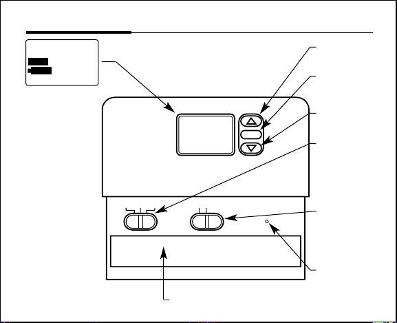
Features (Model 42999)
TEMP
SET TEMP
FILTER
LO BAT
HOLD
■ Easy-To-Read
Digital Display
Liquid crystal
display shows
room
temperature, set
temperature,
filter indicator,
low battery
indicator, heat
and cool system
indicator.
■ Unique Filter
Monitor
Automatically
reminds you to
clean or
replace your
heating and air
conditioning
filters.
69
HEAT COOL
C
■ Easy access battery compartment.
6-7
■ For raising
temperature.
■ To reset filter
counter back
to zero.
■ For lowering
temperature.
■ Function
Switch
For turning
on heating
and cooling
system.
■ Fan ON
and
AUTO
Selector
Switch.
■ Reset Button
For resetting
thermostat.
Page 7
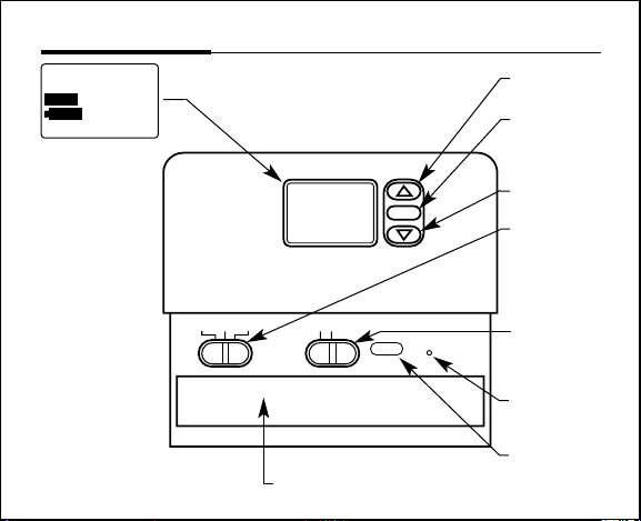
Features (Model 44050)
FILTER
LIGHT
HEAT OFF
COOL
AUTO
FAN
RESET
TEMP
SET TEMP
FILTER
LO BAT
HOLD
■ Easy-To-Read
Digital Display
Liquid crystal
display shows
room
temperature, set
temperature,
filter indicator,
low battery
indicator, heat
and cool system
indicator.
■ Unique Filter
Monitor
Automatically
reminds you to
clean or
replace your
heating and air
conditioning
filters.
69
HEAT COOL
C
■ Easy access battery compartment.
■ For raising
temperature.
■ Display
backlight for
viewing in
the dark.
■ For lowering
temperature.
■ Function
Switch
For turning
on heating
and cooling
system.
■ Fan ON
and AUTO
Selector
Switch.
■ Reset Button
For resetting
thermostat.
■ To reset filter
counter back
to zero.
Page 8
Installation
8-9
What You Need
This thermostat comes with two #8 slotted screws and two wall anchors for mounting. To
install your unit, you should have the following tools and materials.
■ Slotted screwdriver ■ Electric drill and 3/16" bit
■ Hammer ■ Two 1.5V (AA) Size Alkaline batteries
Remove Old Thermostat
CAUTION: Do not remove any wiring from existing thermostat before reading the
instructions carefully. Wires must be labeled prior to removal.
■ IMPORTANT! Turn off the power to the furnace at the main power panel or at the furnace.
■ Remove existing thermostat cover and thermostat. See Figure 1. Some thermostats will have
screws or other locking devices that must first be removed. Once wall mounting plate is
exposed, look for wires.
■ If wires are not visible, they may be connected to the back of the wallplate. Again, look for
screws, tabs, etc. Some models have doors that open to expose wires and mounting screws.
(See Figure 1).
Page 9
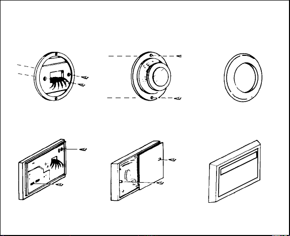
TYPICAL HOME THERMOSTATS
FIGURE 1
Wall Mounting Plate
Wall Mounting Plate
Thermostat
Thermostat
Cover
Cover
Page 10
Installation
W
G
Y
RH
RC
10-11
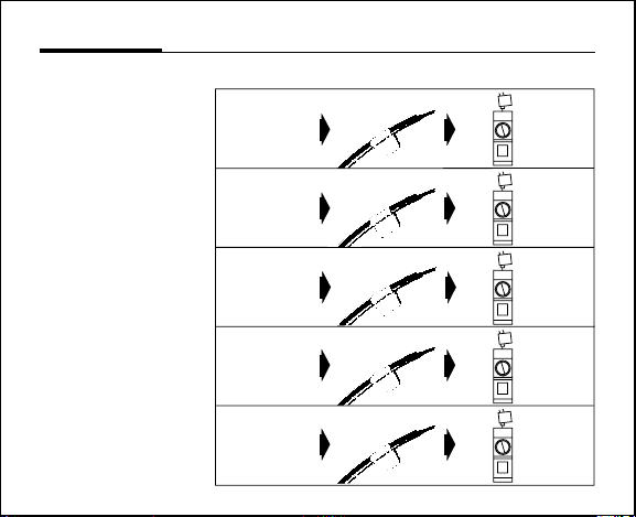
Label Wires
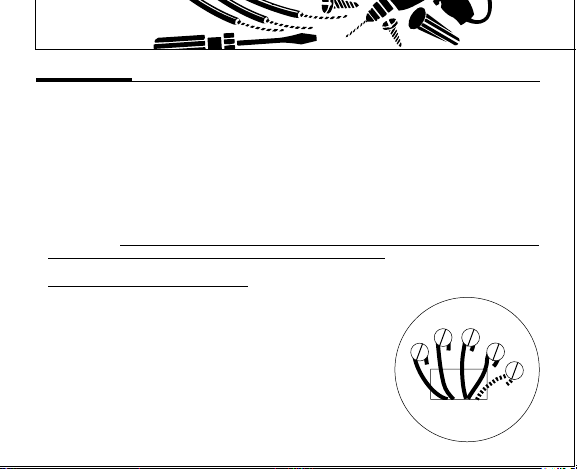
■ Each wire coming from the wall to the existing thermostat is connected to a terminal point on
that thermostat. Each of these terminal points is usually marked with a code letter as shown in
Table A on page 9.
■ The number of wires in your system can be as few as two (for heat only systems), as many as
eight, or any number in between. If you follow the labeling procedures correctly, you do not
have to be concerned about how many wires there are.
■ There is often no terminal marking on the existing thermostat of two wire, heat only systems.
Do not worry, just connect either of the wires to the RH terminal, then connect the other wire
to the W terminal to complete the circuit.
■ IMPORTANT! BEFORE DISCONNECTING ANY WIRES, APPL
PROVIDED TO THE WIRE AS SHOWN IN TABLE A ON PAGE 11. (For example, attach the
label marked W to the wire which goes to the W or H terminal on your existing thermostat.)
IGNORE THE COLOR OF THE WIRES
■ After labeling wires, disconnect them from the existing
thermostat terminals.
■ Remove existing wallplate. To make sure wires do not fall back
■ If hole in wall is larger than necessary for wires, seal this hole so
into wall opening, you may want to tape them to the wall.
that no hot or cold air can enter the back of the thermostat
from the wall. This air could cause a false thermostat reading.
since these do not always comply with the standard.
Y THE SELF-ADHESIVE LABELS
Page 11
Wire Labeling
RH
G
Y
W
RC
RH
RH
RC
RC
G
G
Y
Y
W
W
This table will help you
match the labels to the
wires so you can attach
them to your Hunter
Thermostat.
NOTE: Follow the labels
when connecting wires
since many installations
do not follow color
coding of wires.
TABLE A
If the code letter on your
existing thermostat is
RH, R,
VR or 4
24 Volt
RC, VC
24 Volt Cool
G or F
Fan
Y, C or M
(See Note)
Air Conditioning
W or H
Heating
then mark wire
with label shown
and connect to thermostat
Terminal shown
RED
BLUE
GREEN
YELLOW
WHITE
Page 12
Installation
12-13
Wire Labeling (Continued)
NOTE: If your thermostat has one wire marked R or RH (4-wire system), then leave the
jumper wire between the RH and RC terminals. Otherwise, if you have separate RH and RC
wires (5-wire system), then remove the jumper wire between the RH and RC terminals.
NOTE: Do not connect a “Common” wire (sometimes labelled “C”) to any terminal on this
thermostat. Tape up the wire and do not use.
Page 13
Mount Wallplate and Thermostat
Snap open the wallplate from your thermostat by pressing the release tab on the bottom of
the thermostat.
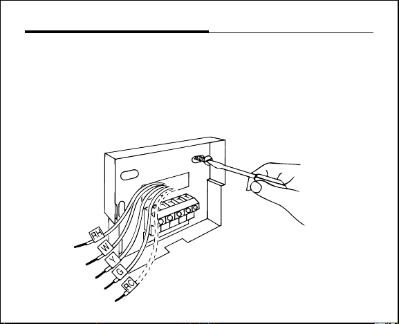
Position wallplate on wall and pull existing wires through large opening. Then level for
appearance. Mark holes for plastic anchors provided if existing holes do not line up with
Hunter Thermostat holes.
Drill holes with 3/16" bit and gently tap anchors into the holes until flush with wall.
Reposition wallplate to wall, pulling wires through large opening. Insert mounting screws
provided into wall anchor and tighten. (See Figure 2.)
FIGURE 2
Page 14
Installation
14-15
Selector Switches
The heating system selector and the F°/C° selector switches are located on the Printed
Circuit Board.
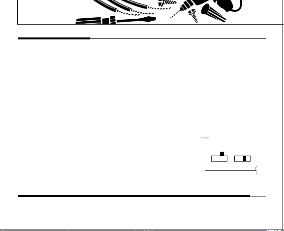
■ Heating system selector
The heating system selector is a switch on the Printed Circuit Board on the inside of the
thermostat. The switch is at “HG” position. Leave it in this position if you have a gas
furnace or an oil burner.
If you have an electric furnace, test to see whether the heat and fan come on as
expected. Leave the switch in the “HG” position. If the fan does not come on when the
thermostat calls for heat, change the switch position to “HE.”
The system selector has no effect in the cooling mode.
NOTE: “HG” position is for gas and most other systems. “HE” position is for certain
electric systems having a fan relay.
■ F°/C° selector (Fahrenheit/Centigrade)
Your thermostat is set for F° mode from the factory. In order to
change to C° mode, slide the switch to C° and press reset
button on the front of the thermostat with a paper clip. The reset
button is located near the display.
NOTE: Unless reset button is pressed, the thermostat will
not change the mode.
HE
HG
C F
Connect Wires and Mount Thermostat Cover to Wall Plate
■ Match and connect the labeled wires to the appropriate coded terminal screws on the
mounting plate. (See Figure 3, 4.) Ignore any wires which may be present, but which were
not connected to the old thermostat.
Page 15
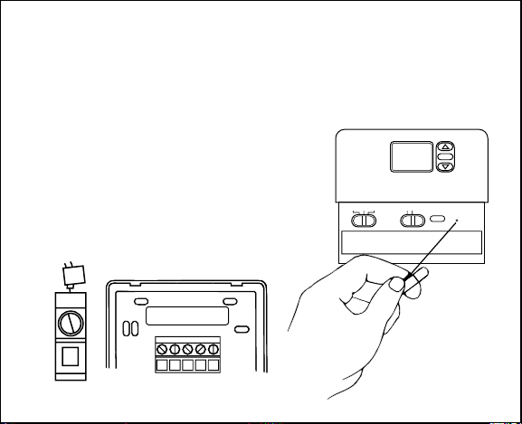
■ Be sure to tighten the terminal screws securely, otherwise a loose wire could cause operational
W
RC RH
YG
RH
RH
HEAT OFF
COOL
AUTO
FAN
RESET
problems with your system or thermostat.
■ Push excess wire back into hole to prevent interference with mounting of the thermostat cover.
■ Make sure the Function Switch is set at OFF, and the FAN-AUTO Switch is in AUTO.
■ Insert the bottom tab on the thermostat body into the slot at the bottom of the wallplate.
Press top of the thermostat body to snap it into the wallplate. (NOTE: Do not force the
thermostat onto the wallplate, as the terminal pins may be damaged. If it does not
snap properly, the thermostat may not work.)
■ Insert the two AA size batteries, observing the polarity
marked on the unit.
■ Switch on the main power. Press the reset button.
(See Figure 5.)
■ The LCD display indicates the current room temperature
of your house. If it shows random numbers or partial
digits, press the reset button once again.
■ The installation is now complete. Continue reading
Owner’s Manual for complete operating instructions.
FIGURE 3
FIGURE 4
FIGURE 5
Page 16
Programming
16-17
Start-Up
When you first install two AA size batteries, as directed in the installation instructions, press
the Reset Button.
■ The thermostat is preset at the factory to 68°F (20°C) for heat and 78°F (25°C) for cool.
■ Room temperature is displayed.
■ Your thermostat batteries will prevent memory loss and avoid reprogramming. Replace
batteries as soon as low battery indicator comes on the display.
■ A built-in timer prevents damage to your air conditioner compressor, caused by rapid cycling,
by providing a delay of 4 minutes before it will restart.
■ The thermostat will display room temperature from 32°F to 99°F. (0°C to 37°C).
■ The temperature can be set from 40°F to 95°F. (5°C to 35°C).
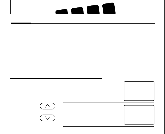
Reviewing Current Temperature Setting
TEMP
SET TEMP
FILTER
LO BAT
HOLD
TEMP
SET TEMP
FILTER
LO BAT
HOLD
69
HEAT COOL
68
HEAT COOL
Press For 2
Seconds Or
Less
■ 69° is current room temperature.
■ 68° indicates the current setting
or
of the thermostat.
■ If pressed for more than 2
seconds, you will adjust the setting as explained below.
F
F
Page 17
Setting New Temperature
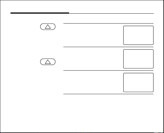
In this example we are raising the current set temperature of 68°F to a new setting of 72°F.
Press
And
Hold
■ Press arrow to display current
temperature setting.
68°F is the current temperature
setting.
■ After 3 seconds, “SET” starts
flashing and temperature digits
will increase.
■ Release at 72°F.
■ The display returns to current
room temperature in 5 seconds.
■ “HEAT” will appear indicating
heat has turned on.
TEMP
SET TEMP
FILTER
LO BAT
HOLD
TEMP
SET TEMP
FILTER
LO BAT
HOLD
TEMP
SET TEMP
FILTER
LO BAT
HOLD
68
HEAT COOL
72
HEAT COOL
69
HEAT COOL
F
F
F
Page 18
LO BAT
LO BAT
.
7I
69
HEAT COOL
69
HEAT COOL
c
c
.
Operations
Filter Monitor
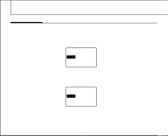
The Hunter Digital Thermostat measures and stores the amount of time the heating or air
conditioning system operated.
After 500 hours of usage, the word “FILTER” will appear and flash on the display, reminding
you to check or replace your system filter.
The word “FILTER” will continue flashing until the filter counter is reset back to zero.
72
TEMP
SET TEMP
HOLD
TEMP
SET TEMP
HOLD
FILTER
FILTER
70
.
18-19
Page 19
To Reset Filter Counter To Zero
TEMP
SET TEMP
Press
Note: Filter button works only when “FILTER” is displayed on the display. If Filter button is
pressed when “FILTER” is not displayed, the internal counter will not reset.
FILTER
FILTER
LO BAT
HOLD
69
HEAT COOL
■ After 5 seconds, when the filter
c
counter is reset, the “FILTER”
disappears from the display.
Temperature Span
Your thermostat is pre-programmed at the
factory to cycle when the temperature rises
1° above or 1° below the temperature
setting. It cannot be changed.
Backlighting (Model 44050 only)
Press
LIGHT
Your thermostat comes with an electroluminescent lamp for easy viewing of the display
in the dark. To activate press the “light”
button between the up and down arrow keys.
The display will remain backlit for
approximately five (5) seconds. If another
button is pushed, the five second timer will
reset, and the light will turn off five seconds
after the last button is pressed.
Page 20
Troubleshooting
Problem
20-21
Solution
SCRAMBLED OR DOUBLE DISPLAY
(numbers over numbers
NO DISPLAY
ENTIRE DISPLAY DIMS
AUTO/FAN DOES NOT COME ON
HEATING OR COOLING DOES NOT GO
ON OR OFF
1. Remove clear mylar sticker.
1. Check battery connections and batteries.
2. Press reset button once with a small pin
and hold in for two seconds.
1. Replace batteries.
1. Move HG/HE system selector to opposite
position.
1. Check that function switch is in correct
position (“HEAT” or “COOL”).
2. There may be as much as 20 seconds
delay before the system turns on - wait
and check.
3. Check your circuit breakers and switches
to ensure there is power to the system.
4. Replace batteries.
5. Make sure your furnace blower door is
closed properly.
6. If your system only uses 4-wires, be sure
the jumper wire is installed between the
RC and RH terminals.
Page 21
ERRATIC DISPLAY
IF UNIT CONTINUES TO OPERATE IN OFF
POSITION
THERMOSTAT READS , HI, LO
PERMANENTLY
If you experience any other problems, call 1-901-745-9222 from 8AM to 5PM Central
Standard time for technical assistance.
1. Press the reset button once with a small
pin and hold in for two seconds. Then
reprogram.
1. Replace unit.
1. Replace unit.
Page 22
Wiring Diagrams
22-23
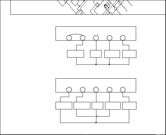
4-wire Heat/Cool System
5-wire Heat/Cool System
Cool
Transformer
Jumper
Heat/Cool
Transformer
Heat
Transformer
THERMOSTAT
G
RHRC
Fan
Relay
THERMOSTAT
G
RHRC
Fan
Relay
W
Heat Relay
or Valve
W
Heat Relay
or Valve
Y
Cool
Contactor
Y
Cool
Contactor
Page 23
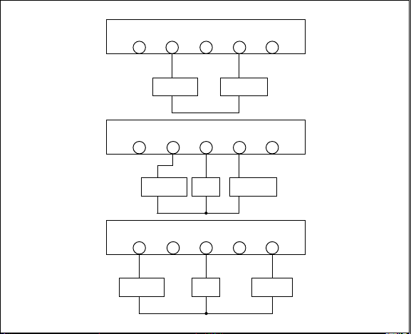
2-wire Heat Only
THERMOSTAT
RHRC
G
W
Y
3-wire Heat Only
3-wire Cool Only
Heat
Transformer
Cool
Transformer
Heat
Transformer
THERMOSTAT
RHRC
THERMOSTAT
RHRC
Fan
Relay
Fan
Relay
G
G
Heat Relay
or Valve
W
Heat Relay
or Valve
W
Y
Y
Cool
Contactor
Page 24
© 1996, Hunter Fan Company Form No. 41251, 5/98
HUNTER FAN COMPANY
2500 FRISCO AVENUE
®
MEMPHIS, TN 38114
 Loading...