

Page 1
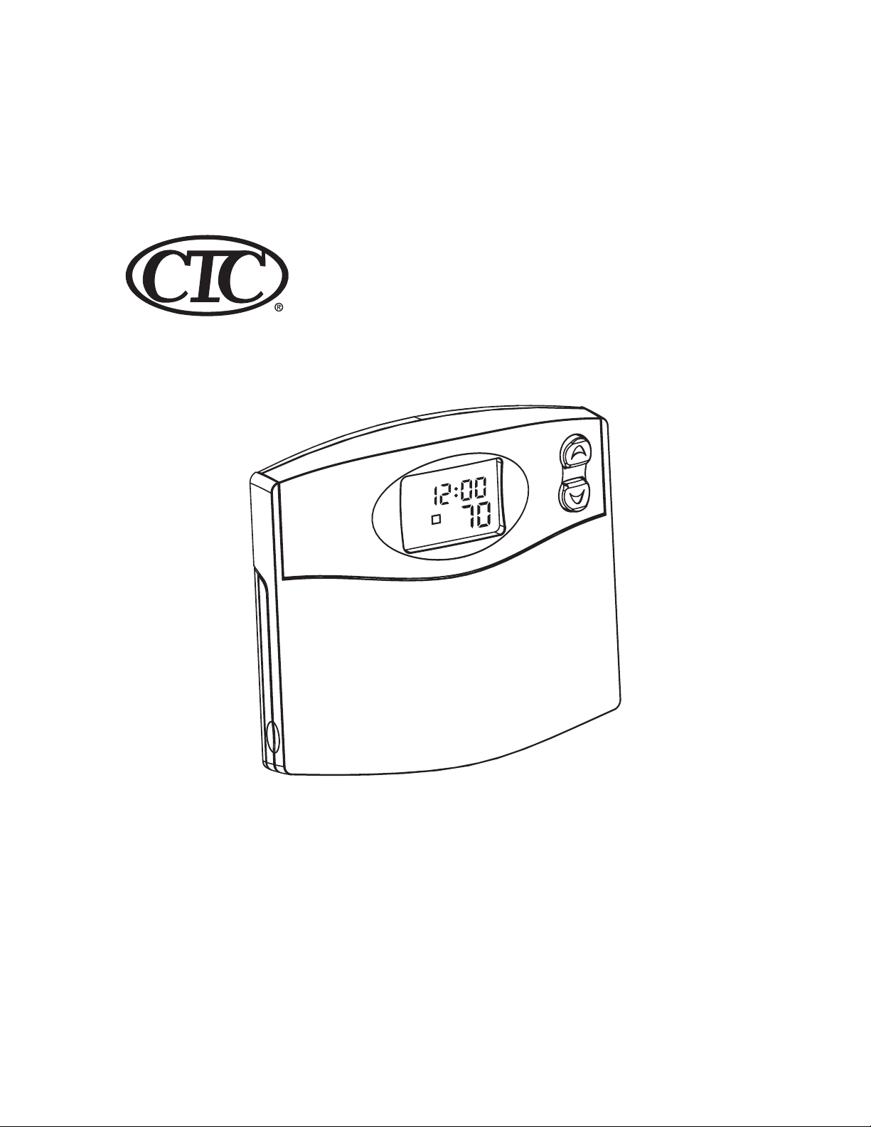
PROGRAMMABLE
THERMOSTAT
M
AM
4
TEMP
Model 43255Owners Manual
Page 2
2
Congratulations!
Your new Climate Technology thermostat will provide years of reliable service. By saving
energy, your thermostat will pay for itself during its first season of use. Thank you for buying a
Climate Technology product!
Please read this manual for complete instructions on installing and operating your thermostat.
If you require further assistance, call Climate Technology Technical Support at 1-800-676-7861
from 8am to 5pm Central Time.
IMPORTANT INFORMATION
1. This thermostat is designed to work on the following systems:
Gas - Standing Pilot Single Stage Heat Pumps - with no auxiliary heat
Gas - Electronic Ignition Electric Furnace
Gas - Fired Boilers Electric Air Conditioning
Gas - Milivolt Systems
Oil - Fired Boilers This thermostat will NOT control multi-stage heat pumps
Oil - Fired Furnace or 110/220 V baseboard electric heating systems.
2. Temperature Range
This thermostat can be programmed between 45˚F and 95˚F (7˚C and 35˚C). It will display
room temperatures from 30˚F to 99˚F (0˚C and 37˚C). “HI” will be displayed if the temperature is higher than 99˚F (37˚C), and “LO” will be displayed if the temperature is
lower than 30˚F (0˚C).
This thermostat will automatically cut-off in Heat mode if the temperature rises above 95˚F
(35˚C), and automatically cut-off in Cool mode if the temperature drops below 40˚F (4˚C).
3. Compressor Protection
This thermostat provides a 3.5 minute delay after shutting off the cooling system before it can
be restarted. This feature will prevent damage to your compressor caused by rapid cycling. It
does not prevent a rapid compressor restart due to short power outages.
4. Battery Warning
Two fresh AA alkaline batteries should provide well over one year of service. However, when
the batteries become drained, the Low Battery Indicator will flash on the display. When this
message occurs, install new alkaline batteries. You have approximately 1 minute to change
the batteries and keep thermostat’s clock and program settings. Once the batteries have
become too low to ensure proper operation, your system will be turned Off, and the display
will be cleared except for flashing Low Battery Indicator on the LCD display.
ENERGY STAR® PARTNER
As an ENERGY STAR® Partner, Climate Technology Corp. has determined that this programmable
thermostat meets the ENERGY STAR
®
guidelines for energy efficiency.
INSTALLATION
What You Need
This thermostat includes two #8 slotted screws and two wall anchors for mounting. To install
your thermostat, you should have the following tools and materials.
■ Slotted Screwdriver(s)
■ Small Philips screwdriver
■ Hammer
■ Electric drill and 3/16” bit
■ Two 1.5 V (AA) size alkaline batteries
Remove Old Thermostat
CAUTION: Do not remove any wiring from existing thermostat before reading the instructions carefully. Wires must be labeled prior to removal.
■ IMPORTANT! Turn off the power to the furnace at the main power panel or at the furnace.
■ Remove existing thermostat cover and thermostat. See Figure 1. Some thermostats will have
screws or other locking devices that must first be removed. Once the wall mounting plate is
exposed, look for wires.
If wires are not visible, they may be connected to the back of the wallplate. Again, look for
screws, tabs, etc. Some models have doors that open to expose wires and mounting screws.
See Figure 1.
Typical Home Thermostats
CAUTION: When only the battery icon flashes on the display, the thermostat is shut down, and your system will no longer operate. In this condition, there is no temperature control of your dwelling.
NOTE: The INDIGLO
®
night-light will not function when the thermostat is in low bat-
tery condition.
NOTE: If you plan to be away from the premises over 30 days, we recommend that
you replace the old batteries with new alkaline batteries prior to leaving.
FEATURES
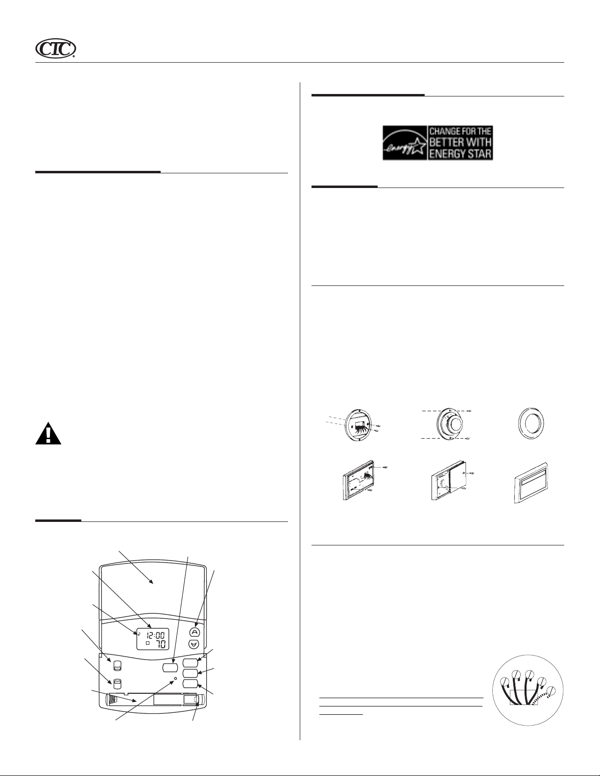
Front Door: Covers keys when not used for neat
appearance. Open by lifting from the bottom
LCD Display: Shows
Time, Day, Temperature,
Program Number, and
other feature information
as required.
Low Battery Indicator:
Flashes when batteries
need to be replaced.
System Switch:
Selector switch for
Heat, Cool, and Off
Fan Switch: Fan
switch for Automatic
or Continuous fan
operation.
Battery Compartment:
Front access allows
easy insertion of two
AA 1.5V batteries.
Reset: Press with a paper clip to reset the
thermostat and return to power-up settings.
off
system
fan
M
AM
heat
cool
auto
on
4
TEMP
Battery Release Lever:
Push to pop batteries loose.
Day / Time Key: Used for entering the Clock
setting mode. Use with the Up and Down keys
to set the time and day.
Up and Down Keys: Keys for
changing the Temperature
setting. Also used for increasing
and decreasing selections in the
Time, Program, and Span
functions.
Program Key: Used for entering
and modifying Programs. Use
with the Up and Down keys to
set times and temperatures.
Press when in Clock setting
mode to select between 12 and
24 hour clock modes.
program
day/time
reset
/return
Filter Key: Resets filter change
filter
counter to zero.
hold
Hold / Return Key: Used for
setting a permanent (vacation)
hold, and for returning to the
normal display from Day & Time
setting, Programming, or Span
setting modes.
Wall Mounting Plate Thermostat Cover
Wall Mounting Plate Thermostat Cover
Figure 1
Wire Labeling
■ Each wire coming from the wall to the existing thermostat is connected to a terminal point on
that thermostat. Each of these terminal points is usually marked with a code letter as shown
in Table A below.
■ Note that this thermostat has multiple function terminals that allow Single-Stage Heat Pump
capability. Standard systems use: Rh, Rc, G, W. [Single-Stage Heat Pumps use: Rh, Y1, G, and O
or B.] Table A below shows the multiple functions of the terminals. Use the terminals that
match your system.
■ The number of wires in your system can be as few as two (for heat only systems), as many as
eight, or any number in between. If you follow the labeling procedures correctly, you do not
have to be concerned about how many wires there are.
■ There is often no terminal marking on the existing thermostat of
two wire, heat only systems. Just connect either of the wires to
the RH terminal, then connect the other wire to the W terminal to
complete the circuit.
■
IMPORTANT! BEFORE DISCONNECTING ANY WIRES, APPLY THE
SELF-ADHESIVE LABELS PROVIDED TO THE WIRE AS SHOWN IN
TABLE A BELOW. (For example, attach the label marked W to the
wire that goes to the W or H terminal on your existing thermostat.) IGNORE THE COLOR OF THE WIRES since these do not always comply with the standard.
Y
G
W
RH
RC
(Continued)
Page 3
3
G
Wire Labeling (Continued)
■ After labeling wires, disconnect them from the existing thermostat terminals.
■ Remove existing wallplate. To make sure wires do not fall back into wall opening, you may
want to tape them to the wall.
■ If hole in wall is larger than necessary for wires, seal this hole with insulating material so that
no hot or cold air can enter the back of the thermostat from the wall. This air could cause a
false thermostat reading.
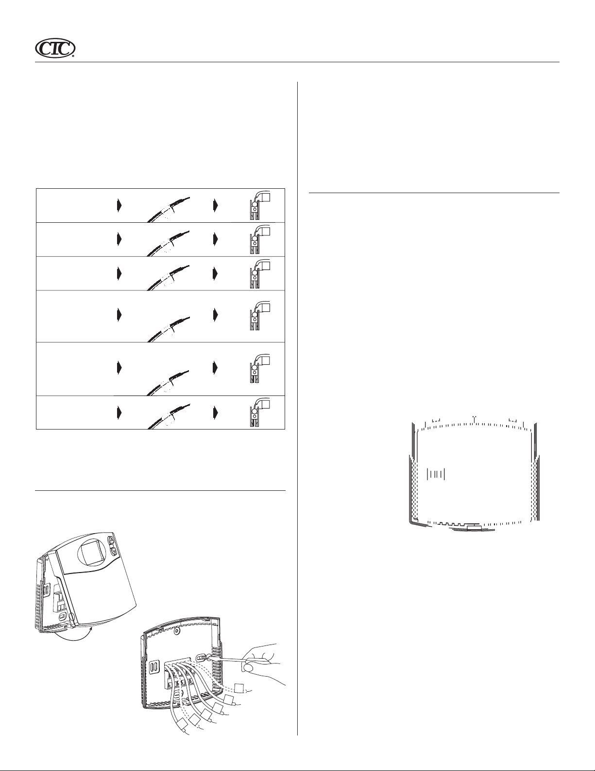
If the code letter on your
existing thermostat is
RH, R, VR or 4
24 Volt
RC, VC
24 Volt Cool
G or F
Fan
Y, C or M
Air Conditioning Compressor
- or O
Reversing Valve operating in Cool mode.
(Single Stage Heat Pumps ONLY.)
W or H
Heating
- or B
Reversing Valve operating in Heat mode.
(Single Stage Heat Pumps ONLY.)
Y1
Heat Pump compressor
(Single Stage Heat
Pumps ONLY.)
then mark the wire
with label shown
RH
C
R
G
Y/O
W/B
Y1
and connect to thermostat
terminal shown
RH
x
RC
x
G
x
Y/O
x
W/B
x
Y1
x
■ Position wallplate on wall and pull existing wires through large opening. Then level for ap-
pearance. Mark holes for plastic anchors provided, if your existing holes do not line up with
those on the Hunter wallplate.
■ Drill holes with 3/16” bit and gently tap anchors into the holes until flush with wall.
■ Reposition wallplate to wall, pulling wires through large opening. Insert mounting screws
provided into wall anchor and tighten. See Figure 3.
NOTE: 5-wire Systems
If your thermostat has one wire marked R or RH (2, 3, or 4-wire system), then leave the jumper
wire between the RH and RC terminals on the wallplate. Otherwise, if you have separate RH and
RC wires (5-wire system), then remove the jumper wire between the RH and RC terminals.
Connect Wires and Mount Thermostat to Wallplate
■ Match and connect the labeled wires to the appropriate coded terminal screws on the
wallplate. (See Figure 4, 5.) Ignore any wires which may be present, but which were not connected to the old thermostat.
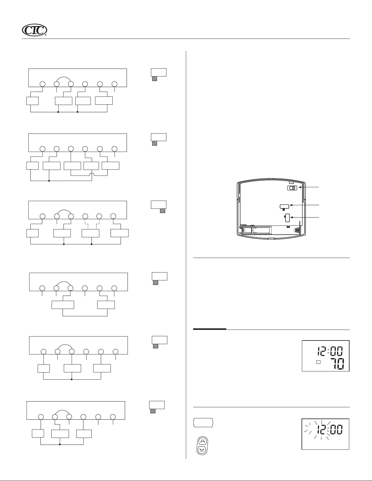
■ Refer to the Wiring Diagrams below to be sure your system is wired correctly.
■ If your system is a single stage heat pump and uses an O or B wire, you must move the Sys-
tem Selector switch inside the thermostat to the Heat Pump position. If you have a normal
furnace or electric system, leave the switch in the Standard position. Refer to the System
Selector section on the back for more information on this switch.
■ Be sure to tighten the terminal screws securely, otherwise a loose wire could cause opera-
tional problems with your system or thermostat.
■ Push excess wire back into the hole to prevent interference when installing the thermostat to
the wallplate.
■ Make sure the System Switch is set to OFF, and the Fan Switch is set to AUTO.
■ Insert the bottom tab on the thermostat body into the slot at the bottom of the wallplate.
Press the top of the thermostat body to snap it into the wallplate. Refer to Figure 6. (NOTE:
Do not force the thermostat onto the wallplate, as the terminal pins may be
damaged. If it does not snap properly, the thermostat may not work.)
■ Insert the two AA size alkaline batteries, observing the polarity marked inside the battery
compartment.
■ Switch on the main power at the panel or furnace.
Table A
NOTE: Do not connect a “Common” wire (sometimes labeled “C”) to any terminal on
this thermostat. Tape up the wire and do not use. This wire provides electricity to nonbattery powered thermostats.
Mount Wallplate and Thermostat
■ Remove the wallplate from your thermostat by pressing the release tab on the bottom of the
thermostat. See Figure 2.
Figure 2
Y1
W
/B
Y/O
Rh
R
c
Figure 3
Figure 4 Figure 5
Page 4
4
Wiring Diagrams
Wallplate
Terminals
Rc
G
Fan
Relay
Wallplate
Terminals
Rc
G
Fan
Cool 24V
Relay
Supply
Wallplate
Terminals
Rc
G
Fan
Relay
Heat Pump
24V Supply
4-wire Heat/Cool System
Jumper
Rh
Y/O
X
Heat/Cool
24V Supply
Cool
Contactor
5-wire Heat/Cool System
No Jumper
Rh
Y/O
Heat 24V
Supply
Cool
Contactor
Single-stage Heat Pump System
Jumper
Rh
Y/O
Cool
X
Mode
Reversing
Valve
OR
W/B
Heat Relay
or Valve
W/B
Heat Relay
or Valve
W/B
Heat
Mode
Y1
X
Y1
X
Y1
Compressor
Contactor
System
Selector
System
Selector
System
Selector
STD
STD
STD
Selector Switches
In order for this thermostat to control your system, the system type must be specified by the
selector switches on the printed circuit board inside the thermostat.
■ Heating System Selector (HG - HE switch)
–
HP
–
HP
–
HP
The factory position for this switch is in the “HG” position. Leave it in this position if you have
a gas furnace or an oil burner. If you have an electric furnace, test to see whether the Heat
and Fan come on as expected after installation. If the Fan operation is normal, leave it in the
“HG” position. If the Fan does not come on within a minute of the thermostat calling for heat,
change the switch position to “HE”. The system selector has no effect in the cooling mode.
NOTE: “HG” position is for gas and most other systems. “HE” position is for certain
electric systems having a fan relay.
■ System Selector (STANDARD - HEAT PUMP switch)
The factory position for this switch is in the STD position. Leave it in this position if you have
ANY system that uses gas, oil, electric, or hot water heating. If you have a single-stage Heat
Pump (no auxiliary or emergency heat source), then slide the switch to the HP position. Be sure
the reversing valve wire is connected to the correct terminal for your heat pump (Y/O) or (W/B).
■ Auto Recovery selector (DISABLE / ENABLE)
Your thermostat is set from the factory with the Auto Recovery Feature enabled, which complies with the EPA ENERGY STAR
®
Program. If you prefer to use normal recovery, slide the
switch to the DISABLE position.
Auto Recovery
DISABLE ENABLE
STD HP
HG HE
(SW4)
System Selector
(SW5)
Fan Option
(SW6)
Wallplate
Terminals
G
X
Heat 24V or
Millivolt Supply
Wallplate
Terminals
G
Fan
Relay
Wallplate
Terminals
Rc
G
Fan
Relay
Cool 24V
Supply
X - No Connection
Jumper
Rc
X
Jumper
Rc
X
Jumper
Connect to Proper Reversing
Valve Terminal. See Table A
2-wire Heat Only System
Rh
Y/O
X
3-wire Heat Only System
Rh
Y/O
X
Heat 24V
Supply
3-wire Cool Only System
Rh
Y/O
X
Cool
Contactor
W/B
Heat Relay
or Valve
W/B
Heat Relay
or Valve
W/B
X
Figure 7
F˚ / C˚ Selection (Fahrenheit / Celcius)
Your thermostat is set for F˚ mode from the factory. To change to C˚ mode, follow these steps:
System
Selector
–
HP
Y1
X
STD
■ Press and hold the Up key.
■ Use a paper clip to press the reset key.
■ Once all the LCD segments turn on, release the Up key.
NOTE: To return to F˚ mode, press the reset key with a paper clip. Do not press any other
keys during the reset process.
All programs and settings will be lost when pressing RESET.
OPERATION
System
Selector
–
HP
System
STD
STD
–
HP
Y1
X
Selector
Y1
X
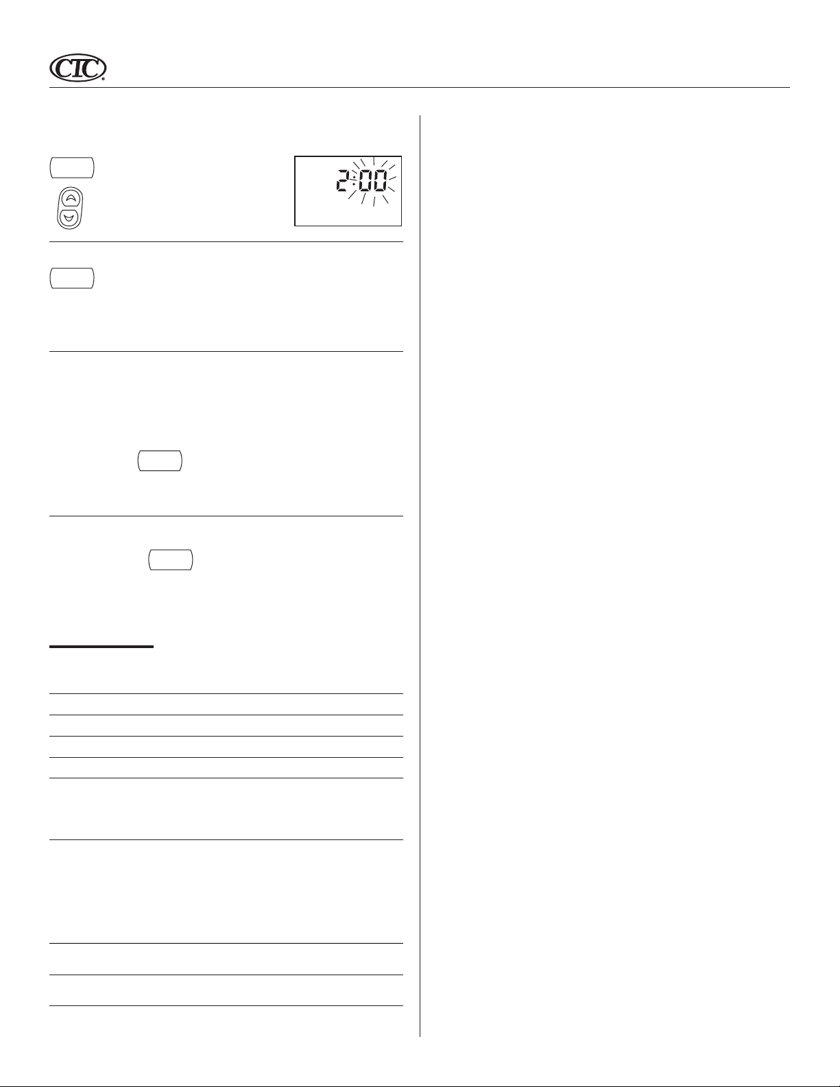
Setting Day and Time
■ The LCD will show this information when
batteries are first installed, or after the
Reset button is pressed. The temperature
will update after a few seconds.
■ During time and day setting mode, the
temperature and program displays will go
blank.
■ Example: Set the Thermostat to the current
time of 2:16 pm on Saturday. Refer to the
Steps below.
STEP 1:
day/time
■ Press to enter time and day setting mode.
The current hour and the AM / PM indicator
will be flashing.
■ Press to change the Hour up or down to the
current hour.
Note the AM / PM indicator, as the display
will change at 12 AM and 12 PM.
M
AM
4
TEMP
M
AM
(Continued)
Page 5
Setting Day and Time (Continued)
STEP 2:
day/time
STEP 3:
day/time
STEP 4:
■ Press again to change from hour setting to
minute setting. The current minute will be
flashing.
■ Press to change the Minute up or down to
the current minute.
■ Press again to change from minute setting
to day setting. The current day will be
flashing.
■ Press to change the Day up or down to the
current day.
■ Press again to change back to the
normal display.
5
M
PM
NOTE: You may press
hold
at any time during Day and Time setting to return to
/return
the normal display.
12 Hr. / 24 Hr. Time Format
Your thermostat is set from the factory in normal 12 (AM / PM) time format. To change to 24
hour (military) time, press
to toggle between the 12 hour and 24 hour formats. The AM / PM indicator will not be dis-
played in 24 hour mode. Both the current time and all programs will automatically change to
the selected format.
program
at any time while the Hour, Minute, or Day is flashing
PROGRAMMING
The following time and temperature settings are pre-programmed into the thermostat:
Temperature in C˚ (F˚)
Program Number Time Heat Cool
1 6:00 am 68˚F (20˚C) 78˚F (26˚C)
2 8:00 am 60˚F (16˚C) 85˚F (29˚C)
3 4:00 pm 68˚F (20˚C) 78˚F (26˚C)
4 10:00 pm 60˚F (16˚C) 82˚F (28˚C)
■ All 7 days of the week have the same default programs.
Personal Program Schedule
■ You can revise the factory programs to match your own schedule. Use this Personal Program
Schedule to determine which times and temperature settings match your comfort and energy
saving requirements. Use a pencil so you can revise your records each time you change your
program settings.
Heating
Day Program 1 Program 2 Program 3 Program 4
Monday – Time Time Time Time
Friday Temp Temp Temp Temp
Saturday Time Time Time Time
Temp Temp Temp Temp
Sunday Time Time Time Time
Temp Temp Temp Temp
Page 6
6
Reviewing Programs
To review your program settings, press
You can also make changes at any time.
program
repeatedly to cycle through the programs.
System Selector Switch
The System Selector switch on the front of the thermostat
determines the operating mode of the thermostat. You may
select COOL, OFF, HEAT.
NOTE: Anytime you install or remove the thermostat
from the wallplate, slide the System Selector to the
OFF position to prevent the possibility of a rapid system On-Off.
off
system
heat
cool
Fan Switch
The Fan switch should normally be located in the AUTO
position. The Fan will be turned on along with normal operation of your system. In a normal gas or oil furnace, the Fan
will be turned on by your furnace after its warm-up delay. For
electric heat, air conditioning, and heat pump operation, the
Fan will turn on with the system.
To run the Fan on continuously, slide the Fan switch to the ON position.
fan
auto
on
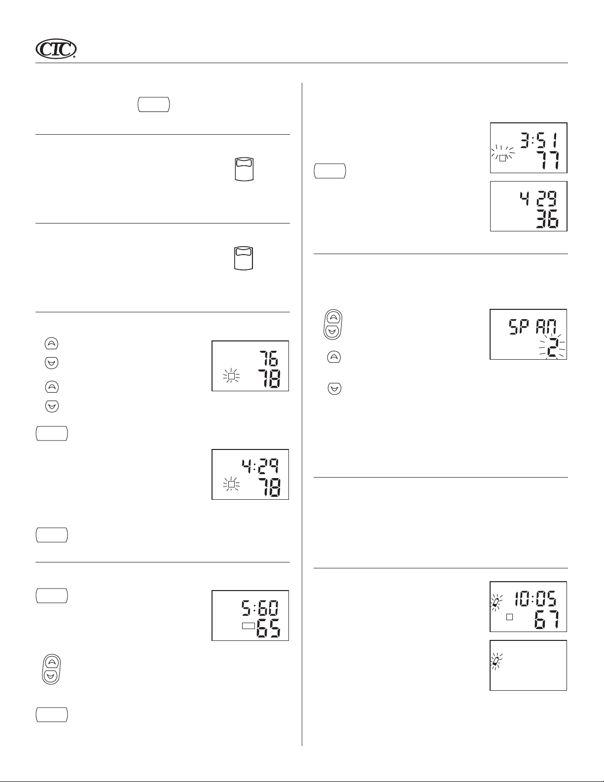
Temporary Manual Override
To temporarily change the current set temperature without affecting your program:
■ Press and hold for about 1 second
or
to enter Manual Override mode. When
display flashes, you can release the key.
■ Press again to change to your desired Set
or
Temperature. Hold the key for 2 seconds to
fast-advance the Set Temperature.
SET TEMP
3
COOL TEMP
Filter Monitor
Your thermostat measures the number of hours your heating and cooling system has been in
use. To maximize your system’s performance and energy efficiency, change or clean your filter
regularly.
filter
■ When the total system runtime for heat and
cool reaches 400 hours, the Filter Change
Indicator will flash as a reminder to check
your system’s filter.
■ Press to review total filter usage. After 15
seconds, the display will return to normal
M T W TH F SA SU SET TEMP
AM
PM
FILTER
2
COOL
TEMP
mode, or you can press the HOLD / RETURN key to exit immediately.
■ After changing or cleaning the system’s
filter, press and hold the Filter Key for 3
seconds. The display will blink, and the
timer will be reset to zero.
SPAN Setting Mode
Your thermostat is set at the factory to cycle at 1˚F (0.5˚C) above and below the set temperature.
(Span = 2) This setting has been designed to provide a comfortable room temperature under
most all conditions. However, if you find your system cycling too fast or too slow, then the Span
can be adjusted to modify the cycle time.
■ Press and hold BOTH for three seconds. The
display will flash, and SPAN will be displayed on the LCD.
■ Press to raise the Span to 3. This setting
INCREASES the cycle time by allowing your
system to run LONGER.
■ Press to lower the Span to 1. This setting
DECREASES the cycle time by causing your
system to run SHORTER.
HR
MIN
hold
/return
■ Press to return to normal mode, or wait 5
seconds for it to return automatically.
■ The current program number will flash to
signify the Temporary Override.
■ At the next program change time, the Tem-
porary Override is cancelled, and the next
program temperature becomes the setpoint
temperature.
SA
PM
3
COOL TEMP
To end the Temporary Manual Override:
hold
/return
■ Press, then press again. This will return the set temperature to the current
program set temperature.
Permanent Override
To hold your Manual Override for vacation or just an extended period of time:
hold
/return
To end the Permanent Manual Override:
hold
/return
■ Press to make the current program tem-
perature the HOLD temperature. HOLD
will be displayed on the LCD, and the
Program number will disappear.
■ Follow the Temporary Manual Override
instructions above to change the Permanent
TH
PM
HOLD
TEMP
Manual Override temperature.
■ You can confirm the held set temperature by
pressing for less than 1 second.
■ Press again. The thermostat will return to the current program, and the HOLD
display will be canceled.
The Span settings remain the same for both HEAT and COOL.
The Span can be changed at any time, and is independent of program times
or temperatures.
When batteries are installed in the thermostat, or the Reset key is pressed, the Span is reset back
to setting 2.
Backlighting (INDIGLO® Night-Light)
Your thermostat has an electroluminescent lamp that backlights the display for easy viewing in
the dark.
When any key is pressed or the System Switch is changed, the display is illuminated.
The display will remain illuminated for 5 seconds after the last key is pressed. This allows the
light to stay on if you need to operate several keys.
Note: If the thermostat is in Low Battery warning condition, the backlight will not
operate. Replace with 2 new alkaline batteries to restore the Backlight function.
Low Battery Warning
Your thermostat has a two-stage low battery warning system.
When the batteries are first detected to be weak, the first stage
low battery warning is indicated by battery symbol flashing on
the LCD display. At your earliest convenience, you need to
replace the batteries with 2 new AA alkaline batteries.
When the batteries become too weak for normal operation,
the thermostat enters the second stage low battery warning
which shuts down the thermostat. In this condition, “BATT”
flashes alone on the display, and the thermostat will turn
your system Off. Your system will remain shut-off until the
batteries are replaced.
Note: The thermostat will still keep the current time and your programs in memory until
new batteries are installed. After confirming that new batteries have been inserted, the
thermostat will return to normal operation.
T
PM
3
HEAT TEMP
Page 7
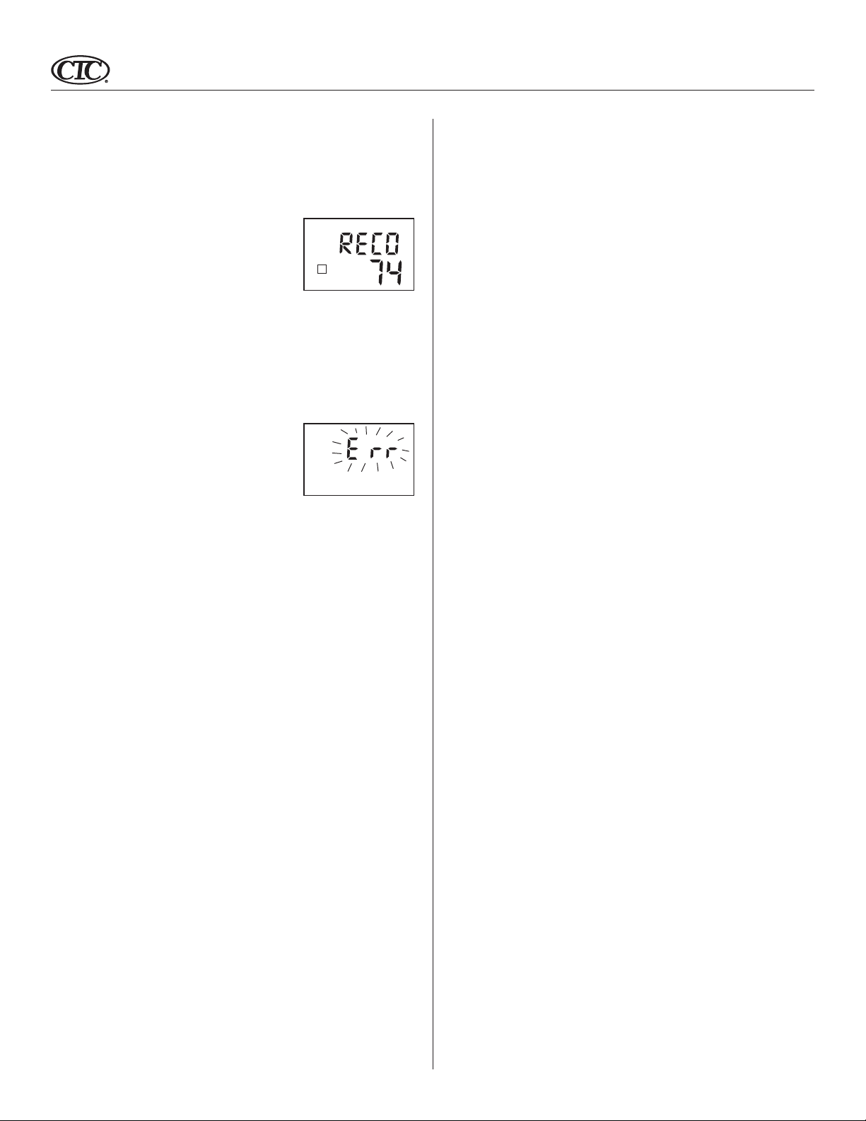
Auto Recovery
Climate Technology’s Auto Recovery feature meets the ENERGY STAR® guidelines for energy
efficiency by allowing the heating or cooling system to recover gradually from an energysaving setpoint temperature to a comfort setpoint temperature.
2
HEAT TEMP
7
 Loading...