

Page 1
Table of Contents
1 • Getting Ready ..................................................................................................................................................................................................................................................... 2
2 • Installing the Ceiling Mounting Plate ......................................................................................................................................................................................................5
3 • Assembling and Hanging the Fan .............................................................................................................................................................................................................7
4 • Setting the Remote Transmitter and Receiver ....................................................................................................................................................................................9
5 • Wiring the Fan ...................................................................................................................................................................................................................................................11
6 • Installing the Ceiling Plate Cover.............................................................................................................................................................................................................13
7 • Assembling the Blades .................................................................................................................................................................................................................................. 14
8 • Activating Auto BalanceTM ..........................................................................................................................................................................................................................15
9 • Completing Your Installation With or
Without a Bowl Light Fixture ...........................................................................................................................................................................................................................16
10 • Operation & Maintenance .......................................................................................................................................................................................................................20
1
42798-01 • 09/16/09 • Hunter Fan Company
Page 2
1 • Getting Ready
Congratulations!
Your new Hunter ceiling fan is an addition to your home or oce that
will provide comfort and reliable performance for many years. We are
proud to supply you with the best ceiling fan available anywhere in
the world.
Before Installation
Before installing your fan, be sure you can do the following:
• Locate the ceiling joist or other suitable support in the ceiling.
• Drill holes and install wood screws or expansion anchors.
• If you have a concrete ceiling, you will need M5 x 30 mm
expansion anchors and screws. (Sold separately)
• Identify and connect electrical wires.• Lift 16 kg (40 lbs).Levantar 16
Kg. (40 lb).
How to Use is Manual:
Be sure to read the entire manual before beginning installation and save
any extra parts for future use. is manual will help you install, operate,
and maintain your new fan. ese instructions are designed to make
installation and assembly as simple and ecient as possible. Each step has
four components:
1. Each step is illustrated at the top of the page. e steps are numbered
on the side of each illustration.
2. Text instructions beneath each illustration describe the procedure for
each step.
3. On the right side of each image, you will nd a life-sized illustration
of necessary hardware. At the bottom of each illustration, there is a
small image that depicts the tools needed for each step. Each image
correlates to the following legend:
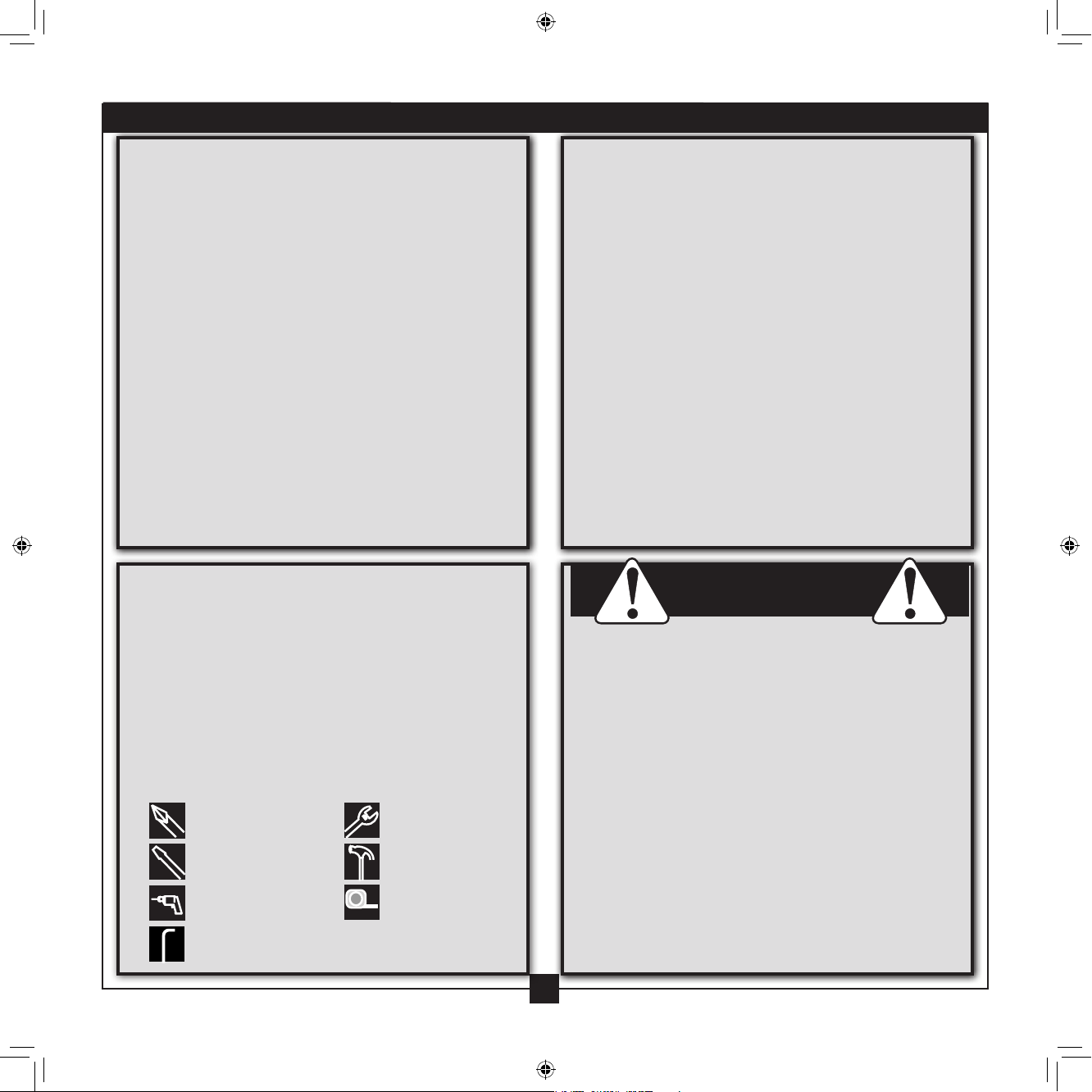
Screwdriver, Phillips-head
Screwdriver, Flat-head
Drill with 3,5 mm bit or
masonry bit (
concrete ceilings)
Allen Wrench
used only for
Wrench
Hammer
Tape Measure
Checking Your Fan Parts
Carefully unpack your fan to avoid damage to the fan parts. Refer to
the included Parts Guide. Check for any shipping damage to the motor
or fan blades. If any parts are missing or damaged, contact your Hunter
dealer or call Hunter Technical Support Department at 888-830-1326.If
you are installing more than one fan, keep the fan blades and blade irons
(if applicable) in sets, as they were shipped.
Optional Accessories
Consider using Hunter’s optional accessories, including a wall-mounted
or remote speed control. To install and use the accessories, follow
the instructions included with each product. For ceilings higher than 8
feet, you can purchase Hunter extension downrods. All Hunter fans use
sturdy 3/4” diameter pipe to assure stability and wobble-free performance
For quiet and optimum performance of your Hunter fan, use only Hunter
speed controls and accessories.
WARNING!
• READ THIS ENTIRE MANUAL CAREFULLY BEFORE BEGINNING
INSTALLATION. SAVE THESE INSTRUCTIONS.
• Use only Hunter replacement parts.
• To reduce the risk of personal injury, attach the fan directly to the
support structure of the building according to these instructions, and use
only the hardware supplied.
• To avoid possible electrical shock, before installing your fan, disconnect
the power by turning o the circuit breakers to the outlet box and
associated wall switch location. If you cannot lock the circuit breakers in
the o position, securely fasten a prominent warning device, such as a tag,
to the service panel.
• All wiring must be in accordance with national and local electrical codes
and ANSI/NFPA 70. If you are unfamiliar with wiring, use a qualied
electrician.
• To reduce the risk of personal injury, do not bend the blade attachment
system when installing, balancing, or cleaning the fan. Never insert foreign
objects between rotating fan blades.
• To reduce the risk of re, electrical shock, or motor damage, do not use a
solid-state speed control with this fan. Use only Hunter speed controls.
2
42798-01 • 09/16/09 • Hunter Fan Company
Page 3
1 • Getting Ready (continued)
Step 1 - Choose the Fan Site
Proper ceiling fan location and attachment to the building structure
are essential for safety, reliable operation, maximum eciency, and
energy savings.
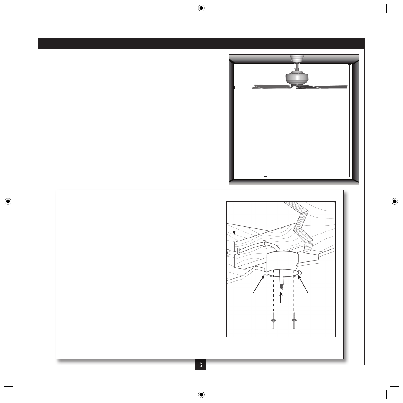
Choose a fan site where:
• No object can come in contact with the rotating fan blades
during normal operation.
• e fan blades are at least 7 feet above the oor and the ceiling is
at least 8 feet high.
• e fan blades have no obstructions to airow, such as walls or
posts, within 30 inches of the fan blade tips.
• e fan is directly below a joist or support brace that will hold the
outlet box and the full weight of the fan.
30” From
Wall or
Nearest
Obstruction
8’ Minimum
Ceiling Height
7’ Minimum
Blades to Floor
Checklist for Existing Fan Site
If you want to use an existing fan site, complete the following checklist to
determine if the site is acceptable and safe for your new Hunter fan. If you
cannot check o every item, prepare a new fan site as described on this
page.
Fan Support System
• Fan attaches directly to building structure.
• Fan support system will hold full weight of the fan and light kit.
Ceiling Hole
• e outlet box clearance hole is directly below the joist or support brace.
.
Outlet Box
• e outlet box is an UL-approved octagonal 4” x 1-1/2” outlet box (or as
specied by the support brace manufacturer).).
• e outlet box is secured to the joist or support brace by wood screws
and washers through the inner holes of outlet box.
• e outer holes of the outlet box are aligned with joist or support brace.
• e bottom of the outlet box is recessed a minimum of 1/16” into ceiling.
Wiring
• e electrical cable is secured to outlet box by an approved connector.
• Six inches of lead wires extend from outlet box.
If your existing fan site is suitable, skip ahead to Section 2 • Installing the
Ceiling Plate.
3
Fan Support System
Fan Support
System
Suitable Existing Fan Site
Outlet Box
Wiring
42798-01 • 09/16/09 • Hunter Fan Company
Page 4
1 • Getting Ready (continued)
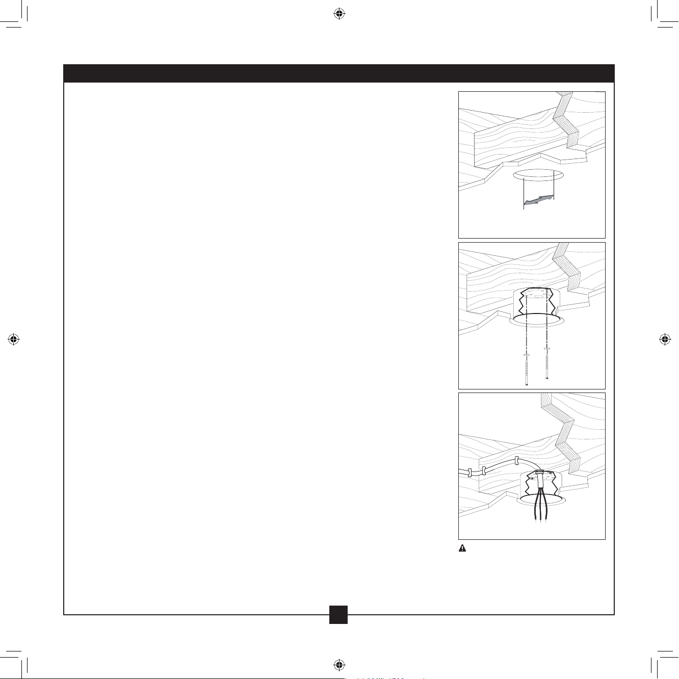
Step 2 - Cut the Ceiling Hole
2-1. Locate the site for the ceiling hole directly below the joist or support brace that will
hold the outlet box and fan.
2-2. Cut a 4” diameter hole through the drywall or plaster of the ceiling. You will use the
hole to install the support brace and outlet box.
Step 3 - Install a Support Brace, If Necessary
Determine if there is a ceiling joist directly above the ceiling hole. If the joist is there,
determine if it is positioned to allow you to recess the outlet box a minimum of 1/16”
into the ceiling. If NOT, install a support brace as follows:
3-1. Attach a 2” x 4” support brace between two joists. Position it to allow you to recess
the bottom of the outlet box a minimum of 1/16” into the ceiling.
3-2. Check the support brace to ensure it will support the full weight of the fan and light
kit.
Step 4 - Install the Outlet Box
4-1. Obtain a UL-approved octagonal 4” x 1-1/2” outlet box, plus two #8 x 1-1/2” wood
screws and washers, available from any hardware store or electrical supply house.
4-2. Orient the outlet box so that both the inner and outer holes in the box align with
the joist or support brace.
4-3. Drill pilot holes no larger than the minor diameter of the wood screws (5/64”)
through the inner holes of the outlet box.
4-4. Attach the outlet box directly to the support brace or joist with two #8 x 1-1/2”
wood screws and washers. e bottom of the outlet box must be recessed a
minimum of 1/16” into the ceiling.
Step 5 - Prepare the Wiring
5-1. Make sure the circuit breakers to the fan supply line leads and associated wall switch
location are turned o . If you cannot lock the circuit breakers in the o position,
securely fasten a prominent warning device, such as a tag, to the service panel.
5-2. read the fan supply line through the outlet box so that the fan supply line extends
at least 6” beyond the box.
5-3. Attach the fan supply line to the outlet box with an approved connector, available
at any hardware store or electrical supply house.
5-4. Make certain the wiring meets all national and local standards and ANSI/NFPA 70.
You have now successfully prepared your ceiling fan site. For instructions to install your
ceiling fan, go to your fan manual and continue with Section 2 • Installing the Ceiling
Plate.
Steps 2 – 3
Step 4
Step 5
CAUTION: All wiring must be in
accordance with national and local
electrical codes and ANSI/NFPA 70. If
you are unfamiliar with wiring, use a
qualied electrician.
4
42798-01 • 09/16/09 • Hunter Fan Company
Page 5
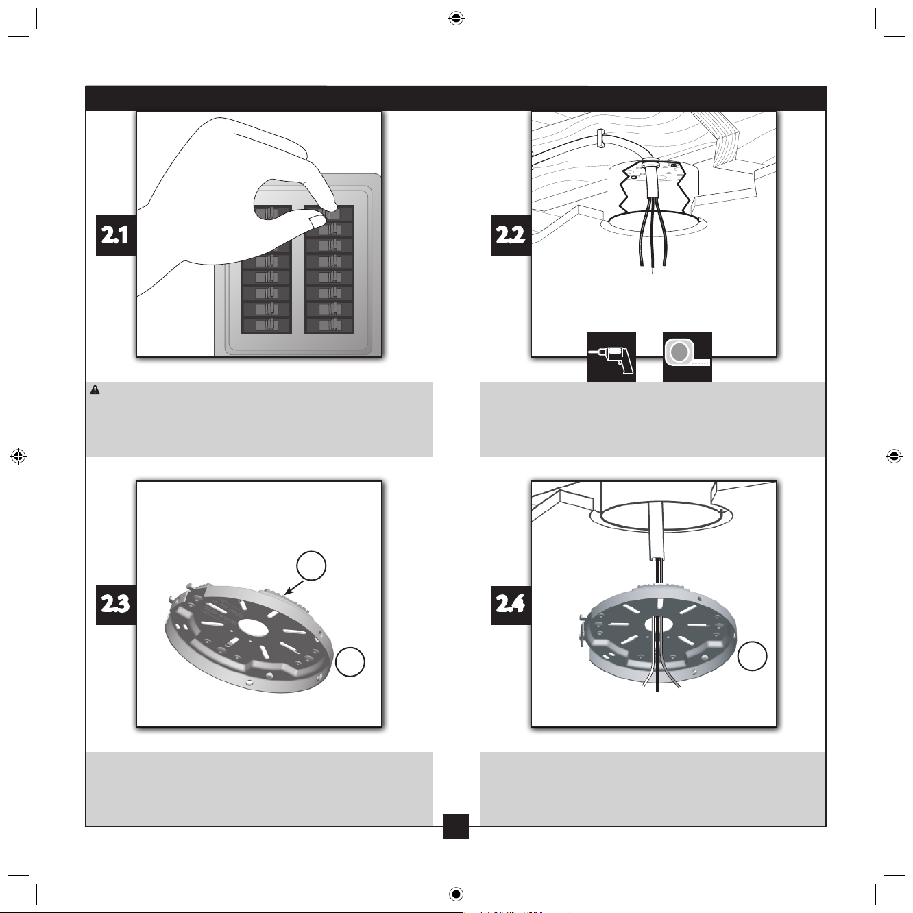
2 • Installing the Ceiling Mounting Plate
2.1
CAUTION: To avoid possible electrical shock, before installing your fan,
disconnect the power by turning o the circuit breakers to the outlet box
and associated wall switch location. If you cannot lock the circuit breakers
in the o position, securely fasten a prominent warning device, such as a
tag, to the service panel.
71
2.3
2.2
Drill two 9/64” pilot holes into the wood support structure through the
outermost holes in the outlet box.
2.4
2
Your ceiling mounting plate (2) comes with four pre-installed noise
isolators (71). Check to make sure all four isolators are in place and were
not removed during shipment.
42798-01 • 09/16/09 • Hunter Fan Company
read the lead wires from the outlet box down through the hole in the
middle of the ceiling mounting plate (2).
5
5
2
Page 6
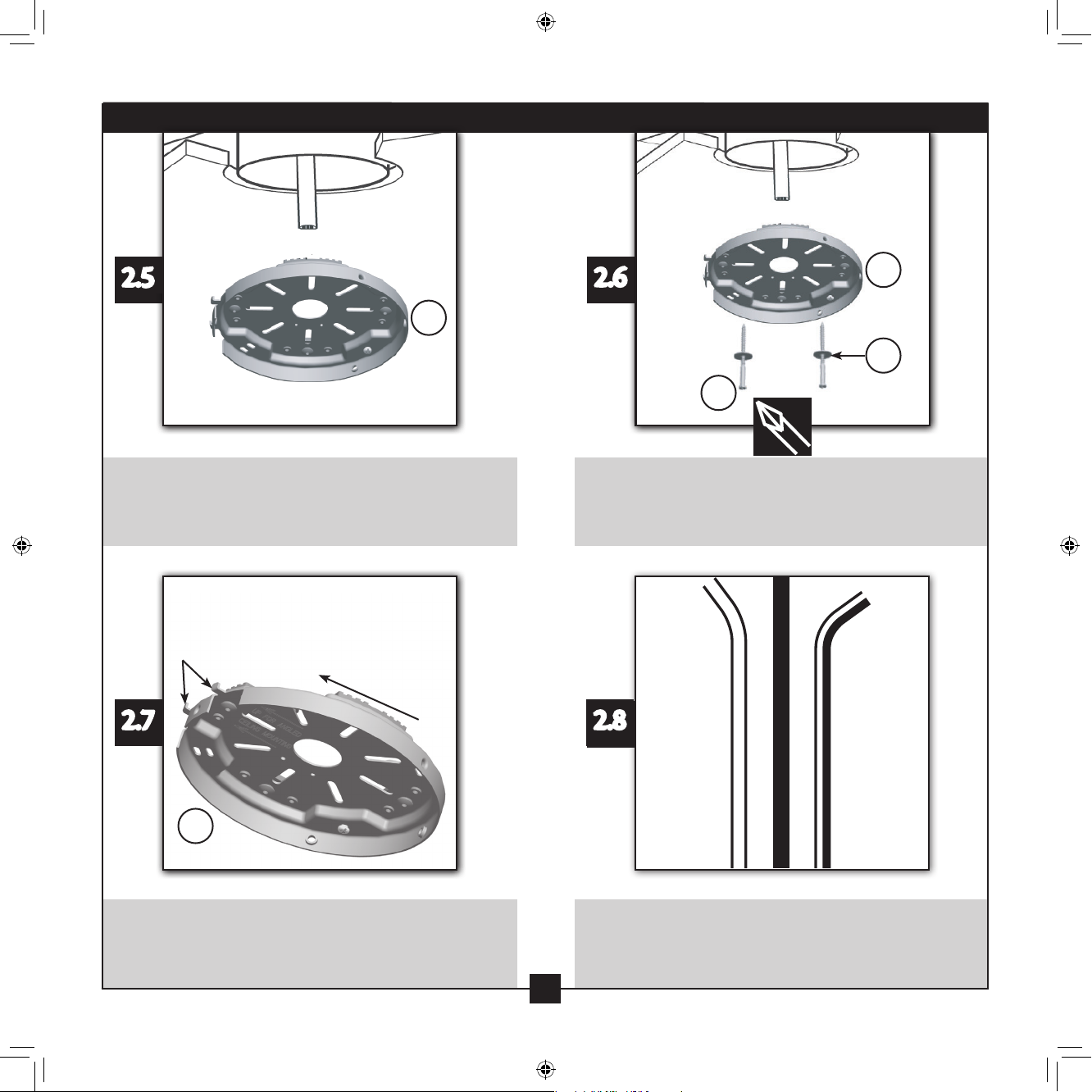
2.5
2 • Installing the Ceiling Mounting Plate (continued)
Note: e
isolators must be
ush against the
ceiling. A loose
ceiling mounting
plate will result
in improper
operation
of the Auto
Balance™system.
2
2.6
65
2
68
Align the slotted holes in the ceiling mounting plate (2) with the pilot
holes you drilled in the wood support structure. For proper alignment, use
slotted holes directly across from each other.
Tabs
Toward
Ceiling Peak
2.7
2
For Angled Ceilings: Be sure to orient the ceiling mounting plate (2) so
that the two tabs are pointing toward the ceiling peak.
Place a at washer (68) on each of the two 3” wood screws (65). Insert
the screws into the slotted holes in the ceiling mounting plate (2) into the
pilot holes you drilled. Tighten the screws (65) into the 9/64” pilot holes;
do not use lubricants on the screws. Do not over tighten.
2.8
Unbundle the wires from the fan.
Note: Your Hunter fan comes with an optional pipe/ball assembly
extension pipe. If you are hanging the fan on a ceiling higher than 10 feet
tall and you would like to use the enclosed optional pipe/ball assembly,
follow Steps 3.5 – 3.9.
6
6
42798-01 • 09/16/09 • Hunter Fan Company
Page 7
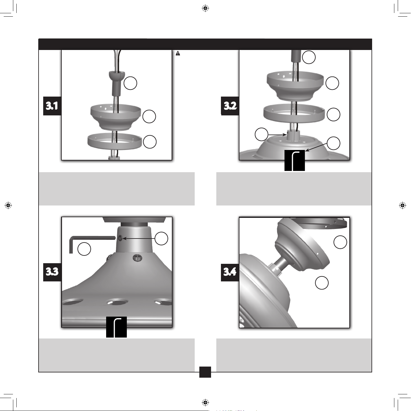
3.1
3 • Assembling and Hanging the Fan
CAUTION:
e motor cover
adapter has a
special coating
on the threads.
7
3
4
Do not remove
this coating; the
coating prevents
the pipe/ball
assembly from
unscrewing. Once
assembled, do not
remove the pipe/
ball assembly.
3.2
7
3
4
8
79
Insert the pipe/ball assembly (7) through the ceiling mounting plate cover
(3) and ceiling mounting plate cover trim ring (4). Feed the wires from the
fan through the pipe/ball assembly (7).
8
79
3.3
Use the Allen wrench (79) to securely retighten the setscrew (8).
Using the provided Allen wrench (79), loosen the setscrew (8) on the
motor cover adapter to install the pipe and ball assembly (7). When the
pipe and ball assembly (7)is fully installed, 2-3 threads on the pipe will still
be visible; this is normal.
2
3.4
3
Raise the fan and align the slots in the ceiling mounting plate cover (3)
with the hooks on the ceiling mounting plate (2). Note: To hang the fan,
you must tilt the ceiling mounting plate cover (3) to an almost vertical
position so that the ceiling mounting plate cover (3) slots sit on the ceiling
mounting plate hooks.
7
7
42798-01 • 09/16/09 • Hunter Fan Company
Page 8

3 • Assembling and Hanging the Fan (continued)
3.5
Place the slots over the hooks to hang the fan.
Pipe
3.7
Pipe Ball
Screw
3.6
Optional Pipe/Ball Instructions:
Your Hunter fan comes with an optional pipe/ball assembly extension
pipe. If you would like to use the enclosed optional 6 inch pipe/ball
assembly, follow Steps 3.6-3.9. Note: e Auto BalanceTM system is
designed for pipe/ball assemblies that are 6” and shorter. If you use a pipe/
ball assembly longer than 6 inches, do not activate the Auto BalanceTM
system.
Pipe
3.8
Pin
Ball
Wedge
Optional Pipe/Ball Instructions: Optional Pipe/Ball Instructions:
Remove the pipe ball screw from the standard pipe/ball assembly, then
slide the ball o the pipe
Remove the pin from the pipe, then slide the wedge o the pipe.
8
8
42798-01 • 09/16/09 • Hunter Fan Company
Page 9

3 • Assembling and Hanging the Fan (continued)
3.9
3.10
Optional Pipe/Ball Instructions: Optional Pipe/Ball Instructions:
Remove the screw and ground wire from the pipe.
4 • Setting the Remote Transmitter and Receiver
4 • Setting the Remote Transmitter and Receiver
When two or more
fans are located near
each other, you may
want to have the
receiver/transmitter
for each fan set to
a diff erent code, so
that the operation
of one fan does not
affect the operation
of the other fans.
Reassemble the ground wire, wedge, pin, ball, and pipe ball screw, in that
order, onto the long pipe/ball assembly. Go back to Step 3.2.
4.1
86
IMPORTANT! Before you change the DIP switch settings, make sure the
battery is not connected to the transmitter.
42798-01 • 09/16/09 • Hunter Fan Company
87
e DIP switches for the receiver (86) are located on the at surface of
the receiver. e DIP switches for the transmitter (87) are in the battery
compartment.
9
9
Page 10

4 • Setting the Remote Transmitter and Receiver(cont.)
Receiver 1
DIP Switches
Set to 0111
4.2
DIP Switches
Set to 0111
Change the position of the DIP switches in the remote transmitter (87) and
the receiver (86). Make sure that the DIP switches match in the remote
receiver (86) and transmitter (87). If they don’t match, the transmitter will
not function.
87
4.4
Receiver 2
DIP Switches
Set to 0100
Transmitter 2Transmitter 1
DIP Switches
Set to 0100
199
Note: Remove the
battery from the
remote control
transmitter if
the product is to
remain unused
for an extended
period of time.
To remove the
battery, remove
the back cover of
the remote control
transmitter.
Remove used
batteries
promptly.
4.3
Toggle Switch
ere is a toggle switch beside the DIP switches on the transmitter (87).
Move the toggle switch toward the side that reads “CFL” if you are going to
operate the fan with the included CFL bulbs. Move the switch to the “INC”
side if you are going to use incandescent bulbs.
87
WARNING:
Use only the
Hunter Fan
speed control
supplied with
this fan.
Install the included 12-Volt, type GP23A battery (199) into the transmitter
(87). Clean the battery contacts and also those of the device prior to
battery installation. Ensure the battery is installed correctly with regard
to polarity (+ and -). Please contact your local battery recycling center for
proper battery disposal information.
42798-01 • 09/16/09 • Hunter Fan Company
e remote control device complies with part 15 of the FCC rules. Changes or
modications not expressly approved by Hunter Fan Company could void your
authority to operate this equipment. Operation is subject to the following two
conditions: 1. is device may not cause harmful interference. 2. is device
must accept any interference received, including interference that may cause
undesired operation.
10
10
Page 11

5 • Wiring the Fan
WARNING!: All wiring must be in accordance with national and local electrical codes and ANSI/NFPA 70. If you are unfamiliar with wiring, use a
qualified electrician. Wall switches are not included. Select an acceptable general-use switch in accordance with national and local electrical codes.
70
To connect the wires, hold the bare metal leads together and place a wire
connector (70) over them, then twist clockwise until tight. For all these
connections use the wire connectors provided.
42798-01 • 09/16/09 • Hunter Fan Company
5.1
Using a large wire connector (70), connect the ground wire (grounding)
from the ceiling to the green ground wire (grounding) from the ceiling
mounting plate and the green ground wire from the pipe/ball assembly
(7).
11
11
Page 12

5 • Wiring the Fan
5.2
Using the large wire connectors (70), connect the white wire and the black
wire from the ceiling as follows:
• e white (common) power wire from the ceiling to the white wire from
the receiver (marked on red tag “NEUTRAL IN”)
• e black power wire from the ceiling to the black wire from the receiver
(marked on red tag “LIVE IN”)
5.4
5.3
Using the small wire connectors (70), connect the wires from the fan as follows:
• e black wire with a white stripe from the fan to the red wire from the receiver
(marked on white tag “LIGHT OUT”)
• e black wire from the fan to the black wire from the receiver (marked on
white tag “FAN OUT”)
WARNING! - Be
sure no bare wire
or wire strands
are visible
after making
connections.
Using the small wire connectors (70), connect the wire from the fan as follows:
• e white wire from the fan to the white wire from the receiver (marked on
white tag “COMMON OUT”)
42798-01 • 09/16/09 • Hunter Fan Company
Push all wires and wire connectors (70), except for the white antenna wire
from the receiver (86), back through the ceiling mounting plate (2) into the
outlet box. Position the receiver (86) in the ceiling mounting plate cover so
that the antenna is close to the edge for clear reception.
12
12
Page 13

6 • Installing the Ceiling Plate Cover
3
2
6.1
Tab
7
Groove
Rotate the pipe/ball assembly (7) so the tab in the ceiling mounting plate
cover (3) is secure in the hanger ball groove. Note: Your fan may have
multiple tabs and grooves that must be aligned.
62
6.3
3
6.2
Swing the fan up to align the ceiling mounting plate cover screw holes
with the mounting holes on the ceiling mounting plate(2).
3
3
6.4
Holding the ceiling mounting plate cover (3) up with the screw holes
aligned, partially install two ceiling mounting plate cover screws (62) into
the holes opposite the ceiling mounting plate tabs.
42798-01 • 09/16/09 • Hunter Fan Company
Partially install a ceiling mounting plate cover screw (62) between the slots
in the ceiling mounting plate cover (3). When all the holes are properly
aligned, securely tighten all three ceiling mounting plate cover screws.
Verify that the tabs in the ceiling mounting plate cover are still in the
grooves of the hanger ball.
13
13
Page 14

6 • Installing the Ceiling Plate Cover(continued)
3
3
6.66.5
4
4
Align the tabs on the trim ring opposite the grooves in the hanger ball.
Using both hands, push the ceiling mounting plate cover trim ring (4) up
to the top of the ceiling mounting plate cover. e ceiling mounting plate
cover trim ring will snap and lock into place.
Should you need to remove the trim ring, press rmly on opposite sides of
the trim ring (4) directly above the groove in the hanger ball. e tabs will
ex out releasing the ceiling mounting plate cover trim ring (4).
7 • Assembling the Blades
66
7.1 7.2
46
Squeeze the rubber blade grommets (66) into the holes in the blades (46).
Attach each blade (46) to a blade arm (98) using three blade assembly
screws (67). e blades may appear slightly loose after screws are
tightened. is is normal.
67
46
98
14
14
42798-01 • 09/16/09 • Hunter Fan Company
Page 15

7 • Assembling the Blades (continued)
7.47.3
47
98
47
Loosen (DO NOT REMOVE) the blade-to-arm screws (47) that are holding
the shipping bumpers in place. Push the shipping bumpers in, then lift
them o.
8 • Activating Auto Balance
Note: After the
retaining screws
Red Retaining
Screws
8.1
If you are using one of the enclosed pipe/ball assemblies, it is now time
for you to activate the Auto BalanceTM system by removing the ve red
retaining screws. Rotate the blades slowly until one of the red retaining
screws is visible through the notch in the mounting plate. Remove the
retaining screw from the bottom of the fan housing using a screwdriver.
Repeat this process for all 5 retaining screws.
are removed,
the blades will
feel loose. is
is normal, as
loose blades are
a characteristic
of the Auto
BalanceTM
system.
Slide the blade arms (98) onto the blade-to-arm screws (47). Tighten the
blade-to-arm screws (47) as tight as possible with a screwdriver.
TM
8.2
If you are using a pipe/ball assembly longer than 6 inches, leave the
retaining screws in their place and continue the installation process.
15
15
42798-01 • 09/16/09 • Hunter Fan Company
Page 16

9 • Completing Your Installation With or Without a Bowl Light Fixture
9.29.1
69
30
Partially install inner switch housing screws (69) into the switch housing
mounting plate.
9.3
30
69
Align the keyhole slots in the upper switch housing with the inner switch
housing screws (69). Turn the housing counterclockwise until the inner
switch housing screws (69) are rmly situated in the narrow end of the
keyhole slots. Install the remaining screw into the housing. Tighten all
three screws rmly.
Feed the upper plug connector through the center opening of the upper
switch housing (30).
Your Hunter fan comes with an integrated light xture assembly and an optional
switch housing cap and plug button. is feature gives you the option of installing
the fan with OR without the included light xture. If you want to install the
light fixture, proceed with Step 9.4 now. If you do not want to install the light
fixture, you need to remove it now. See “Removing the Light Fixture” on Step 9.10.
Once you have removed the light xture, continue with Step 9.4.
16
16
42798-01 • 09/16/09 • Hunter Fan Company
Page 17

9 • Completing Your Installation With or Without a Bowl Light Fixture (cont.)
Note: Both plug
connectors are
polarized and
will only t
together one way.
Make sure the
connectors are
properly aligned
9.4
31
before connecting
them. Incorrect
connection could
cause improper
operation and
damage to the
product.
9.5
30
131
Connect the upper plug connector from the fan body to the lower plug
connector in the lower switch housing assembly (31).
9.6
259
Install the included Pin-Based CFL bulb (259), 26 Watt Maximum, into the
socket.
Place the lower switch housing assembly (31) over the upper switch
housing (30). Align the side screw holes in the upper and lower switch
housings. Attach the lower switch housing to the upper switch housing
with three outer switch housing screws (131).
9.7
Install the included Pin-Based CFL bulb (259), 26 Watt Maximum, into the
socket.
17
17
42798-01 • 09/16/09 • Hunter Fan Company
Page 18

9 • Completing Your Installation With or Without a Bowl Light Fixture (cont.)
150
9.8
150
Lift the glass bowl (150) up so the threaded nial rod ts through the hole
in the glass bottom.
9.10
9.9
148
Place the cover plate (148) up against the glass bowl (150). Align the holes
in the cover plate (148) with the grommet hole of the metal disc..
9.11
149
Screw the nial (149) onto the threaded nial rod end until tight.
42798-01 • 09/16/09 • Hunter Fan Company
Removing the Light Fixture
Disconnect the plug connectors between the black wire and the black
wire with a white stripe. Disconnect the plug connectors between the two
white wires.
18
18
Page 19

9 • Completing Your Installation With or Without a Bowl Light Fixture (cont.)
9.11
Removing the Light Fixture
Remove the nut and washer from inside the center of the lower switch
housing.
9.13
9.12
Removing the Light Fixture
Unscrew the light bulb socket.
9.14
Removing the Light Fixture
Pull the large (male) plug connector through the hole in the center of the
lower switch housing. en, pull out the small (female) connector.
42798-01 • 09/16/09 • Hunter Fan Company
Removing the Light Fixture
Remove the light xture bracket by removing the 2 screws attaching the
bracket to the lower switch housing.
19
19
Page 20

9 • Completing Your Installation With or Without a Bowl Light Fixture (cont.)
9.15
Removing the Light Fixture
Install the switch housing cap and plug button to the lower switch
housing.
You can mount the remote holder to any toggle switch plate with the
screws already in the switch plate. Or, you can simply mount the remote
holder on the wall.
After your installation is complete, restore power to the fan. Wash your
hands after installing the fan.
20
20
42798-01 • 09/16/09 • Hunter Fan Company
Page 21

10 • Operation & Maintenance
Cleaning and Maintenance
Caring for nishes:
For cleaning nishes, use a soft brush or lint-free cloth to prevent
scratching. A vacuum cleaner brush nozzle can remove heavier
dust. Remove surface smudges or accumulated dirt and dust
using a mild detergent and a slightly dampened cloth. You may
use an artistic agent, but never abrasive cleaning agents as they
will damage the nish.
Caring for blades:
Note: Be careful to not bend the blades when cleaning.
Clean wood nish blades with a furniture polishing cloth.
Occasionally, apply a light coat of furniture polish for added
protection and beauty. Clean painted and high-gloss blades in the
same manner as the fan nish.
If you need parts or service assistance, please call 888-8301326 or visit us at our Web site at http://www.hunterfan.com.
Hunter Fan Company
7130 Goodlett Farms Parkway #400
Memphis, Tennessee 38016
Airflow Direction
Ceiling fans work best by blowing air downward
(counterclockwise blade rotation) in warm weather to cool the
room with a direct breeze. In winter, having the fan draw air
upward (clockwise blade rotation) will distribute the warmer air
trapped at the ceiling around the room without causing a draft.
Winter
Upward Airflow
Clockwise
Summer
Downward Airflow
Counterclockwise
21
42798-01 • 09/16/09 • Hunter Fan Company
Page 22

10 • Operation & Maintenance
Operation
e fan pull chain controls power to the fan.
• e pull chain has four settings in sequence: High, Medium,
Low, and O.
• Pull the chain slowly to change settings.
• Release slowly to prevent the chain from recoiling into the
blades.
• e chain uses a breakaway connector that separates if the
chain is jerked. If this happens, simply reinsert the chain into
the connector.
e light pull chain controls the power to the light fixture.
• e chain has two settings: ON and OFF.
Problem: Noisy operation
• Tighten the blade assembly screws and blade iron armature
screws until snug.
• Check to see if a blade is cracked. If so, replace all the blades.
Troubleshooting
Problem: Nothing happens; fan does not move.
• Turn power on, replace fuse, or reset breaker.
• Loosen canopy, check all connections according to the wiring
the fan section.
• Check the plug connection in the switch housing.
• Push motor reversing switch rmly left or right to ensure that
the switch is engaged.
• Pull the pull chain to ensure it is on.
• Remove the shipping bumpers.
Other Hunter Products
Oscillating Fans
Humidiers
Problem: Excessive wobbling
If your fan wobbles when operating, use the enclosed balancing
kit and instructions to balance the fan.
Tighten all blade iron screws.
Turn power o , support fan very carefully, and check that the
hanger ball is properly seated.
If you have tried these troubleshooting solutions and still
have trouble, visit our Web site at:
http://www.hunterfan.com.
Hunter Fan Company
7130 Goodlett Farms Parkway #400
Memphis, Tennessee 38016
42798-01 • 09/16/09 • Hunter Fan Company
22
Air Puriers
Thermostats
To learn more about Hunter Fan Company
products, please see our Web page at:www.
hunterfan.com
Bath Fans
Ceiling Fans
 Loading...