

Type 3 ModelsType 3 ModelsType 3 Models
Form# 42797-01
20081113
©2008 Hunter Fan Co.
For Your Records and
Warranty Assistance
For reference, also attach your receipt or a copy
of your receipt to the manual.
__________________________________________
Model Name
__________________________________________
Model No.
__________________________________________
Date Purchased
__________________________________________
Where Purchased
English Español
Owner’s Guide and Installation Manual
Westside II
21621
2
42797-01 • 11/13/08 • Hunter Fan Company
© 2008 Hunter Fan Company
Your new Hunter® ceiling fan is an addition to your home or oce that
will provide comfort and performance for many years. is installation
and operation manual gives you complete instructions for installing
and operating your fan.
We are proud of our work. We appreciate the opportunity to supply
you with the best ceiling fan available anywhere in the world.
Before installing your fan, for your records and warranty assistance,
record information from the carton and Hunter nameplate label
(located on the top of the fan motor housing).
Cautions and Warnings
• READ THIS ENTIRE MANUAL CAREFULLY BEFORE BEGINNING
INSTALLATION. SAVE THESE INSTRUCTIONS.
• Use only Hunter replacement parts.
• To reduce the risk of personal injury, attach the fan directly to the
support structure of the building according to these instructions,
and use only the hardware supplied.
• To avoid possible electrical shock, before installing your fan,
disconnect the power by turning o the circuit breakers to the
outlet box and associated wall switch location. If you cannot lock
the circuit breakers in the o position, securely fasten a prominent
warning device, such as a tag, to the service panel.
• All wiring must be in accordance with national and local electrical
codes and ANSI/NFPA 70. If you are unfamiliar with wiring, use a
qualied electrician.
• To reduce the risk of personal injury, do not bend the blade
attachment system when installing, balancing, or cleaning the fan.
Never insert foreign objects between rotating fan blades.
• To reduce the risk of re, electrical shock, or motor damage, do not
use a solid-state speed control with this fan. Use only Hunter speed
controls.
Welcome
Table Of Contents
1 • Getting Ready......................4
2 • Installing the Ceiling Plate ..........5
3 • Assembling the Top Housing .......6
4 • Assembling and Hanging the Fan ...7
5 • Setting the Remote Transmitter and
Receiver...........................8
6 • Wiring the Fan .....................9
7 • Installing the Canopy ...............11
8 • Assembling the Blades..............12
9 • Completing Your Installation .......13
10 • Operating the Remote Control and
Mounting the Holder..............14
11 • Operating and Cleaning Your Ceiling
Fan ...............................15
12 • Troubleshooting ..................16
3
42797-01 • 11/13/08 • Hunter Fan Company
Installer’s Choice and Optional Accessories
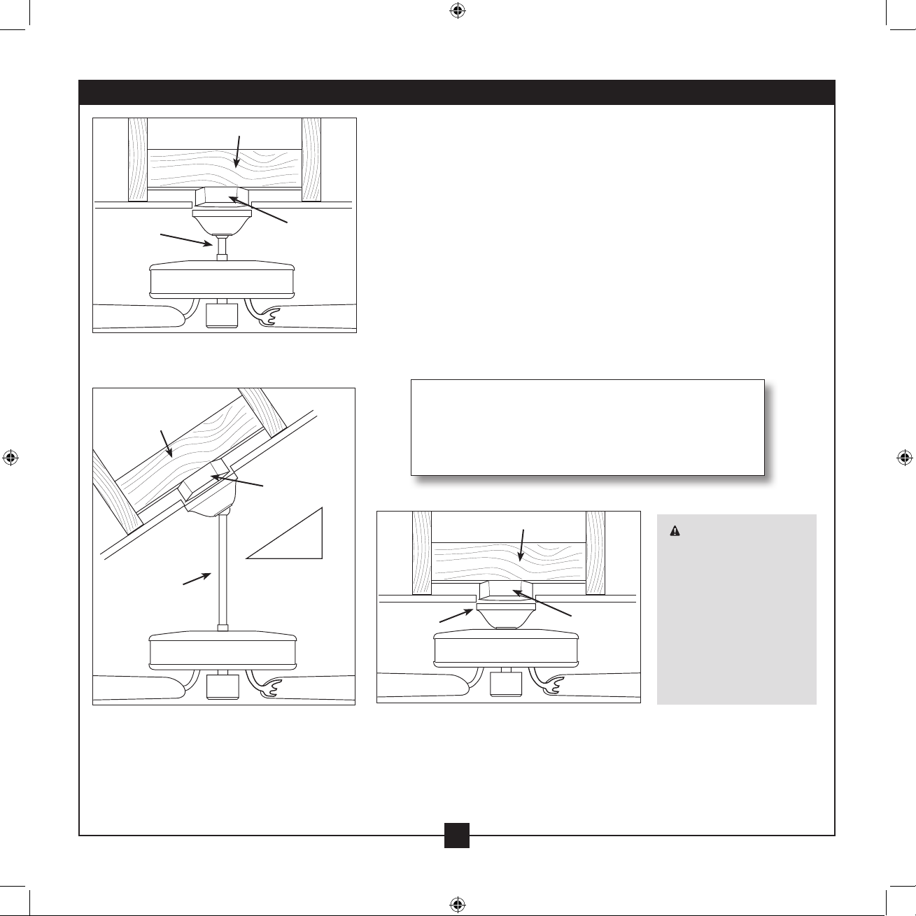
Understanding Mounting and Installer’s Choice®
Hunter’s patented 3-position mounting system provides you maximum
installation exibility and ease. You can install your Hunter fan in one
of three ways, depending on ceiling height and your preference: Low
Prole, Standard, or Angled mounting. e steps in this manual include
instructions for all three Installer’s Choice mounting methods.
Considering Optional Accessories
Consider using Hunter’s optional accessories, including a wall-mounted
or remote speed control. To install and use the accessories, follow
the instructions included with each product. For quiet and optimum
performance of your Hunter fan, use only Hunter speed controls.
For ceilings higher than 8 feet, you can purchase
Hunter extension downrods. All Hunter fans use
sturdy 3/4 in. diameter pipe to assure stability and
wobble-free performance.
Standard Mounting hangs from the
ceiling by a downrod (included).
Angled Mounting recommended for a
vaulted or angled ceiling
Support Brace
Standard
Mounting
Style
Ceiling
Outlet Box
Support Brace
Ceiling
Outlet Box
Angled
Mounting
Style
Low Profile Mounting ts close to the
ceiling, recommended for ceilings less
than 8 feet high
Support Brace
Low Prole
Mounting
Style
Ceiling
Outlet Box
8
12
CAUTION: To
reduce the risk of
personal injury, attach
the fan directly to the
support structure of
the building according
to these instructions,
and use only the
hardware supplied.
4
42797-01 • 11/13/08 • Hunter Fan Company
To install a ceiling fan, be sure you can do the following:
• Locate the ceiling joist or other suitable support in ceiling.
• Drill holes for and install wood screws.
• Identify and connect electrical wires.
• Lift 40 pounds.
If you need help installing the fan, your Hunter fan dealer can direct
you to a licensed installer or electrician.
Gathering the Tools
You will need the following tools for installing the fan:
• Electric drill with 9/64 in. bit
• Standard screwdriver (magnetic tip recommended)
• Phillips-head screwdriver (magnetic tip recommended)
• Wrench or pliers
• Ladder (height dependent upon installation site)
Checking Your Fan Parts
Carefully unpack your fan to avoid damage to the fan parts. Refer to
the included Parts Guide. Check for any shipping damage to the motor
or fan blades. If any parts are missing or damaged, contact your Hunter
dealer or call Hunter Technical Support Department at 888-830-1326.
Preparing the Fan Site
Before you begin installing the fan, follow all the instructions in
the pullout sheet called “Preparing the Fan Site.” Proper ceiling fan
location and attachment to the building structure are essential for
safety, reliable operation, maximum eciency, and energy savings.
Installing Multiple Fans?
If you are installing more than
one fan, keep the fan blades and
blade irons (if applicable) in sets,
as they were shipped.
1 • Getting Ready
5
42797-01 • 11/13/08 • Hunter Fan Company
CAUTION: To avoid possible electrical shock, before installing your fan,
disconnect the power by turning o the circuit breakers to the outlet box
and associated wall switch location. If you cannot lock the circuit breakers
in the o position, securely fasten a prominent warning device, such as a
tag, to the service panel.
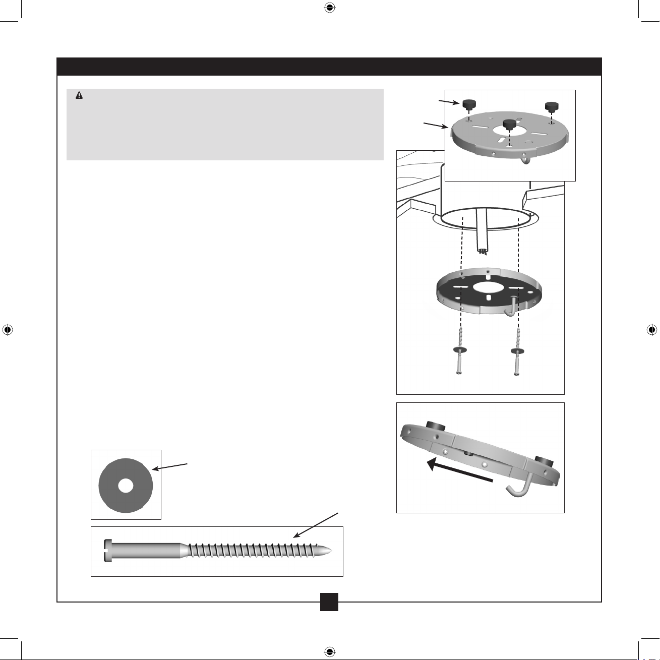
2-1. Drill two pilot holes into the wood support structure through the
outermost holes in the outlet box. e pilot holes should have a
diameter of 9/64 in.
2-2. Your fan comes with three neoprene noise isolators (“Isolators”).
Position the isolators between the ceiling plate and ceiling by
inserting the raised areas on each isolator into the holes in the
ceiling plate.
2-3. read the lead wires from the outlet box down through the hole
in the middle of the ceiling plate.
2-4. Align the slotted holes in the ceiling plate with the pilot holes you
drilled in the wood support structure. For proper alignment use
slotted holes directly across from each other.
Note: e isolators should be ush against the ceiling.
2-5. Place a at washer on each of the two 3 in. wood screws and pass
the screws through the slotted holes in the ceiling plate into the
pilot holes you drilled.
Tighten the screws into the 9/64 in. pilot holes; do not use
lubricants on the screws. Do not over tighten.
Step 2-2
Flat Washer
3 in. Wood Screw
Steps 2-3 – 2-5
For Angled Ceilings: Be sure to orient
the ceiling plate so that the hook and
one of the threaded screw holes in the
ceiling plate are on the lower side.
Ceiling
Plate
Isolator
2 • Installing the Ceiling Plate
6
42797-01 • 11/13/08 • Hunter Fan Company
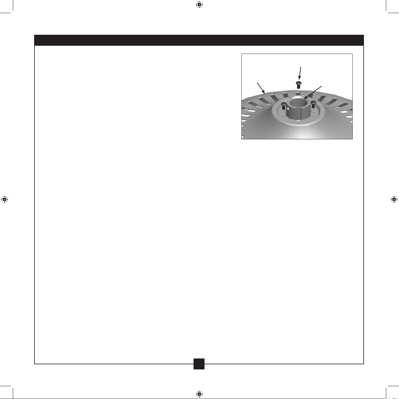
3 • Assembling the Top Housing
3-1. To assemble the housing to the hanger adapter, align the three
raised tabs on the hanger adapter with the three narrow notches
in the top housing. Make certain the housing sits at on the
adapter.
3-2. Install three (3) assembly screws and tighten them securely.
Steps 3-1 – 3-2
Top Housing
Assembly Screw
Hanger Adapter
 Loading...