

Page 1
For Your Records and
Warranty Assistance
For reference, also attach your receipt or a copy
of your receipt to the manual.
Type 3 ModelsType 3 ModelsType 3 Models
__________________________________________
Model Name
__________________________________________
Model No.
__________________________________________
Date Purchased
__________________________________________
Where Purchased
Owner’s Guide and Installation Manual
English Español
Form# 42649-01
20090813
©2009 Hunter Fan Co.
Page 2
Welcome
Your new Hunter® ceiling fan is an addition to your home or oce that
will provide comfort and performance for many years. is installation
and operation manual gives you complete instructions for installing
and operating your fan.
We are proud of our work. We appreciate the opportunity to supply
you with the best ceiling fan available anywhere in the world.
Before installing your fan, for your records and warranty assistance,
record information from the carton and Hunter nameplate label
(located on the top of the fan motor housing).
Table Of Contents
1 • Getting Ready. . . . . . . . . . . . . . . . . . . . . . 4
2 • Installing the Ceiling Plate . . . . . . . . . . 5
3 • Setting the Remote Transmitter and
Receiver . . . . . . . . . . . . . . . . . . . . . . . . . . 6
4 • Wiring the Fan . . . . . . . . . . . . . . . . . . . . . 7
5 • Installing the Canopy and Canopy Trim
Ring . . . . . . . . . . . . . . . . . . . . . . . . . . . . . . 9
6 • Assembling the Blades . . . . . . . . . . . . . 10
7 • Completing Your Installation With a
Bowl Light Fixture. . . . . . . . . . . . . . . . . 11
8 • Operating the Remote Control and
Mounting the Holder . . . . . . . . . . . . . 12
9 • Operating and Cleaning Your Ceiling
Fan . . . . . . . . . . . . . . . . . . . . . . . . . . . . . . . 13
10 • Troubleshooting . . . . . . . . . . . . . . . . . . 15
Cautions and Warnings
• READ THIS ENTIRE MANUAL CAREFULLY BEFORE BEGINNING
INSTALLATION. SAVE THESE INSTRUCTIONS.
• Use only Hunter replacement parts.
• To reduce the risk of personal injury, attach the fan directly to the
support structure of the building according to these instructions,
and use only the hardware supplied.
• To avoid possible electrical shock, before installing your fan,
disconnect the power by turning o the circuit breakers to the
outlet box and associated wall switch location. If you cannot lock
the circuit breakers in the o position, securely fasten a prominent
warning device, such as a tag, to the service panel.
• All wiring must be in accordance with national and local electrical
codes and ANSI/NFPA 70. If you are unfamiliar with wiring, use a
qualied electrician.
• To reduce the risk of personal injury, do not bend the blade
attachment system when installing, balancing, or cleaning the fan.
Never insert foreign objects between rotating fan blades.
• To reduce the risk of re, electrical shock, or motor damage, do not
use a solid-state speed control with this fan. Use only Hunter speed
controls.
© 2009 Hunter Fan Company
2
42649-01 • 08/13/09 • Hunter Fan Company
Page 3
Installer’s Choice and Optional Accessories
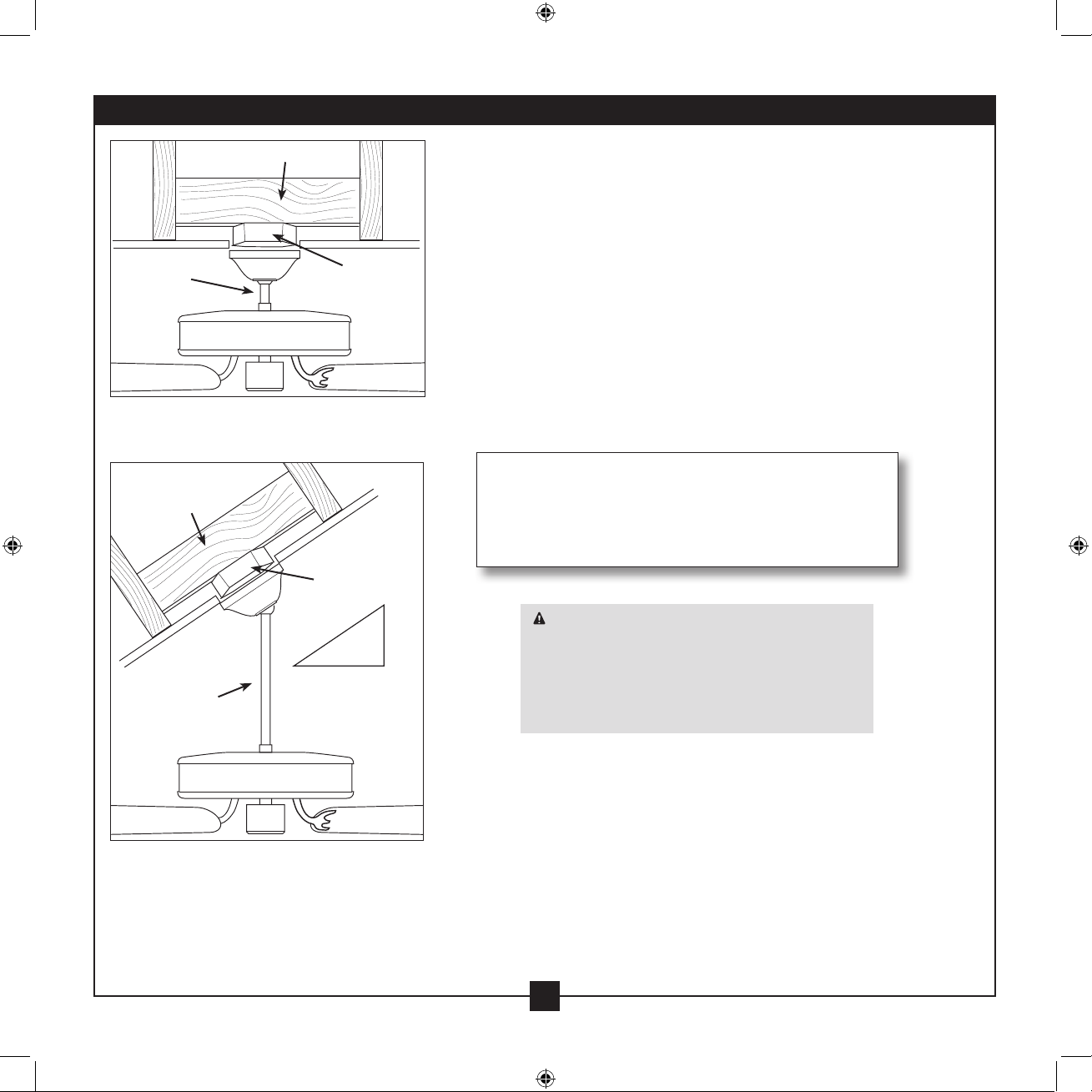
Support Brace
Standard
Mounting
Style
Standard Mounting hangs from the
ceiling by a downrod (included).
Support Brace
Ceiling
Outlet Box
Angle
Mounting
Style
Ceiling
Outlet Box
12
Understanding Mounting and Installer’s Choice®
Hunter’s patented 2-position mounting system provides you maximum
installation exibility and ease. You can install your Hunter fan in one
of two ways, depending on ceiling height and your preference: Standard
or Angled mounting. e steps in this manual include instructions for
both Installer’s Choice mounting methods.
Considering Optional Accessories
Consider using Hunter’s optional accessories, including a wall-mounted
or remote speed control. To install and use the accessories, follow
the instructions included with each product. For quiet and optimum
performance of your Hunter fan, use only Hunter speed controls.
For ceilings higher than 8 feet, you can purchase
Hunter extension downrods. All Hunter fans use
sturdy 3/4” diameter pipe to assure stability and
wobble-free performance.
8
CAUTION: To reduce the risk of personal
injury, attach the fan directly to the support
structure of the building according to these
instructions, and use only the hardware
supplied.
Angled Mounting recommended for a
vaulted or angled ceiling
42649-01 • 08/13/09 • Hunter Fan Company
3
Page 4
1 • Getting Ready
1 • Getting Ready
To install a ceiling fan, be sure you can do the following:
• Locate the ceiling joist or other suitable support in ceiling.
• Drill holes for and install wood screws.
• Identify and connect electrical wires.
• Lift 40 pounds.
If you need help installing the fan, your Hunter fan dealer can direct
you to a licensed installer or electrician.
Gathering the Tools
You will need the following tools for installing the fan:
• Electric drill with 9/64” bit
• Standard screwdriver (magnetic tip recommended)
• Phillips-head screwdriver (magnetic tip recommended)
• Wrench or pliers
• Ladder (height dependent upon installation site)
Checking Your Fan Parts
Carefully unpack your fan to avoid damage to the fan parts. Refer to
the included Parts Guide. Check for any shipping damage to the motor
or fan blades. If any parts are missing or damaged, contact your Hunter
dealer or call Hunter Technical Support Department at 888-830-1326
(In Canada, call 1-866-268-1936).
Installing Multiple Fans?
If you are installing more than
one fan, keep the fan blades and
blade irons (if applicable) in sets,
as they were shipped.
Preparing the Fan Site
Before you begin installing the fan, follow all the instructions in
the pullout sheet called “Preparing the Fan Site.” Proper ceiling fan
location and attachment to the building structure are essential for
safety, reliable operation, maximum eciency, and energy savings.
4
42649-01 • 08/13/09 • Hunter Fan Company
Page 5
2 • Installing the Ceiling Plate
CAUTION: To avoid possible electrical shock, before installing your fan,
disconnect the power by turning o the circuit breakers to the outlet box
and associated wall switch location. If you cannot lock the circuit breakers
in the o position, securely fasten a prominent warning device, such as a
tag, to the service panel.
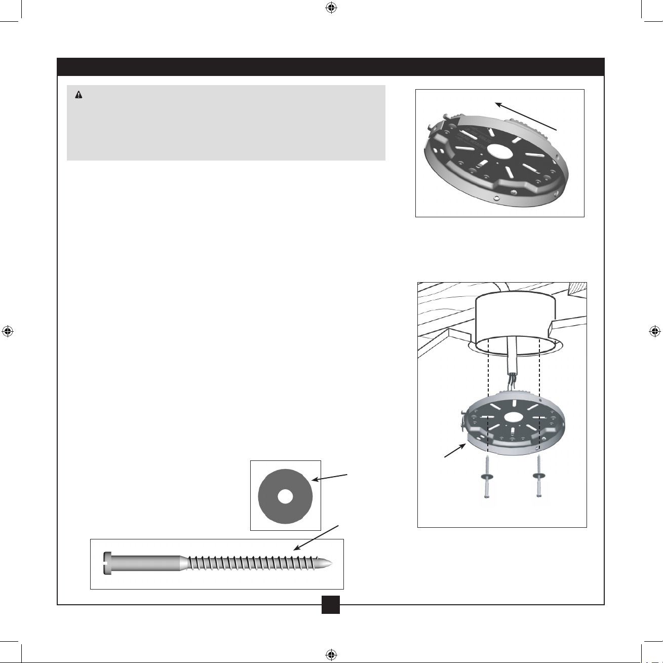
2-1. Drill two pilot holes into the wood support structure through the
outermost holes in the outlet box. e pilot holes should be 9/64”
in diameter.
For Angled Ceilings: Be sure to orient the ceiling plate so that the
two tabs are pointing toward the ceiling peak.
2-2. Seperate the ceiling plate from the remote control receiver.
2-3. Your fan comes with four preinstalled noise isolators. Check to
make sure all four isolators are in place and were not removed
during shipment.
2-4. Place a at washer on each of the two 3” wood screws.
2-5. read the supply wires from the outlet box in the ceiling through
the hole in the center of the ceiling plate.
2-6. Align the slotted holes in the ceiling plate with the pilot holes you
drilled in the wood support structure. For proper alignment use
slotted holes directly across from each other.
Note: e isolators should be ush against the ceiling.
2-7. Pass the screws through the slotted holes in the ceiling plate into
the pilot holes you drilled.
Tighten the screws into the 9/64” pilot holes; do not use lubricants
on the screws. Do not over tighten.
Flat Washer
Toward
Ceiling Peak
For Angled Ceilings: Be sure to orient
the ceiling plate so that the two tabs
are pointing toward the ceiling peak.
Ceiling
Plate
3” Wood
Screw
5
42649-01 • 08/13/09 • Hunter Fan Company
Steps 2-4 – 2-7
Page 6

4 3 2 1
4 3 2 1
4 3 2 1
4 3 2 1
4 3 2 1
4 3 2 1
3 • Setting the Remote Transmitter and Receiver
You must now set the jumpers in the remote transmitter and receiver
so that they match.
3-1. Change the position of the jumpers in the transmitter and the
receiver. Be sure the position of the jumper in the transmitter
matches the position of the jumper in the receiver. If they don’t
match, the controller will not function. For instructions on how to
set the jumpers, read the box below.
3-2. Clean the battery contacts and also those of the device prior to
battery installation.
3-3. Ensure the battery is installed correctly with regard to polarity
(+ and -).
Setting Jumpers
When two or more fans are located near each other, you may desire to
have the receiver/transmitter for each fan set to a dierent code, so that
the operation of one fan does not aect the operation of the other fans.
In the transmitter you can access the jumpers from the battery
compartment. e jumpers are very small. You can move them most
easily using a small pair of pliers or tweezers. IMPORTANT! Before
you change a jumper, make sure the battery is not connected to the
transmitter.
Example Jumpers Settings
Receiver 1 Receiver 2
Transmitter 2Transmitter 1
CAUTION: e remote control device complies with part 15 of the FCC rules.
Changes or modications not expressly approved by Hunter Fan Company could void
your authority to operate this equipment.
Operation is subject to the following two conditions:
1. is device may not cause harmful interference.
2. is device must accept any interference received, including interference that may
cause undesired operation.
Note: Use with a fan that incorporates an air gap switch (normal on-o wall switch).
WARNING: Maximum fan load is 1 Amp; maximum lamp is 19 Watts. Do not use
any speed control with this product.
6
42649-01 • 08/13/09 • Hunter Fan Company
Page 7

4 • Wiring the Fan
All wiring must be in accordance with national and local electrical
codes and ANSI/NFPA 70. If you are unfamiliar with wiring, use a
qualified electrician.
Wall switches are not included. Select an acceptable general-use switch
in accordance with national and local electrical codes.
4-1. Before attempting installation, make sure the power is still o.
4-2. Place the receiver inside the canopy, making sure that the
dipswitches and the oval shaped holes in the bottom of the
receiver are facing down toward the bottom of the canopy.
4-3. Spread the receiver lead wires to each side and feed the wires from
the top of the fan through the open slot in the receiver.
4-4. Place the receiver in the canopy. Make sure the slot in the receiver
is aligned with the hook in the ceiling plate.
4-5. To connect the wires, hold the bare metal leads together and
place a wire connector over them, then twist clockwise until tight.
Using the small wire connectors, connect the fan to the receiver as
follows:
• Connect the yellow wire (ungrounded) from the fan to the
yellow wire (ungrounded) from the receiver.
• Connect the white wire (ungrounded) from the fan to the
white wire (ungrounded) from the receiver (marked on white
tag “LIGHT NEUTRAL OUT”).
• Connect the pink wire (ungrounded) from the fan to the pink
wire (ungrounded) from the receiver.
• Connect the grey wire (ungrounded) from the fan to the grey
wire (ungrounded) from the receiver.
• Connect the black/white wire (ungrounded) from the fan to
the black/white wire (ungrounded) from the receiver (marked
on white tag “LIGHT LIVE OUT”).
• Connect the red wire (ungrounded) from the fan to the red
wire (ungrounded) from the receiver.
Receiver
A
B
C
Step 4-7
A • Ground/Green
Step 4-6
B • Receiver Black: “AC LIVE IN”
• Ceiling Black
C • Receiver White: “AC NEUTRAL IN”
• Ceiling White
Step 4-5
D • Fan Yellow
• Receiver Yellow
E • Fan White
• Receiver White: “LIGHT NEUTRAL OUT”
F • Fan Pink
• Receiver Pink
G • Fan Grey
• Receiver Grey
H • Fan Black/White
• Receiver Black/White: “LIGHT LIVE OUT”
I • Fan Red
• Receiver Red
Small Wire
connector
D
Steps 4-5 – 4-7
E
I
H
G
F
7
42649-01 • 08/13/09 • Hunter Fan Company
Page 8

Large Wire
Connector
4 • Wiring the Fan (continued)
4-6. Using the large wire connectors, connect the fan and receiver to
the power wires as follows:
• Connect the black wire (ungrounded) from the receiver
(marked on white tag “AC LIVE IN”) to the black wire
(ungrounded) from the ceiling.
• Connect the white wire (ungrounded) from the receiver
(marked on white tag “AC NEUTRAL IN”) to the white wire
(ungrounded) from the ceiling.
CAUTION: Be sure no bare wire or wire strands are visible after
making connections.
4-7. Connect the green ground wires (grounded) from the ceiling
plate and the downrod to the ground wire from the ceiling.
4-8. Run the thin white antenna wire from the receiver through one
of the slots in the ceiling plate. (For best reception, make sure the
end of the antenna is exposed at the top of the canopy.)
4-9. Turn the splices upward and push them carefully back through
the ceiling plate into the outlet box.
4-10. Spread the wires apart, with the grounded wires on one side of
the outlet box and the ungrounded wires on the other side of the
outlet box.
8
42649-01 • 08/13/09 • Hunter Fan Company
Page 9

5 • Installing the Canopy and Canopy Trim Ring
WARNING: Failure to complete the following steps could cause the fan
to fall.
Note: It is recommended you use a magnetic tip screwdriver for the
following steps.
5-1. Rotate the hanger ball so the tab in the canopy is secure in the
hanger ball groove. Note: Your fan may have multiple tabs and
grooves that must be aligned.
5-2. Swing the fan up to align the canopy screw holes with the
mounting holes on the ceiling plate.
WARNING: e slots in the canopy must remain engaged while
swinging the canopy for alignment.
5-3. Holding the canopy up with the screw holes aligned, partially
install two canopy screws into the holes opposite the ceiling plate
tabs.
5-4. Partially install a canopy screw between the slots in the canopy.
When all the holes are properly aligned, securely tighten all three
canopy screws.
5-5. Verify that the tabs in the canopy are still in the grooves of the
hanger ball.
5-6. Align the tabs on the trim ring opposite the grooves in the hanger
ball. Using both hands, push the canopy trim ring up to the top of
the canopy. e canopy trim ring will snap and lock into place.
Note: Should you need to remove the trim ring, press rmly on
opposite sides of the trim ring directly above the groove in the
hanger ball. e tabs will ex out releasing the canopy trim ring.
Step 5-1
Tab
Groove
Step 5-2
Step 5-3
Canopy
Canopy
Trim
Ring
Canopy Screw
9
42649-01 • 08/13/09 • Hunter Fan Company
Page 10

6 • Assembling the Blades
6-1. Insert blade through housing before installing grommets in
each blade.
6-2. Attach each blade to the fan using two blade assembly
screws.
Grommet
10
42649-01 • 08/13/09 • Hunter Fan Company
Blade Assembly
Screw
Page 11

7 • Completing Your Installation With a Bowl Light Fixture
Installing the Glass Bowl
7-1. Partially install two screws in the upper light kit.
7-2. Align the keyholes in the upper light kit ring with
the partially installed screws and rotate to situate
the screws in the narrow ends of the keyholes.
7-3. Install the remaining screw into the upper light kit
ring and securely tighten all three screws.
7-4. Install included 18W CFL bulb.
7-5. Align the tabs in the globe assembly with the tabs
in the light kit ring, then lift the globe assembly
and rotate to engage the tabs. Make sure all tabs
are properly engaged before releasing the globe.
Note: In compliance with US federal energy regulations, this
ceiling fan contains a device that restricts the light
kit to a maximum of 190 Watts. Exceeding that limit
or the marked limit on this product may result in re
hazard or improper operation.
Screws
Steps 7-1 - 7-3
Bulb
Steps 7-4 - 7-5
11
42649-01 • 08/13/09 • Hunter Fan Company
Glass Bowl
Page 12

8 • Operating the Remote Control and Mounting the Holder
8-1. e remote transmitter has individual buttons for turning the fan
o and on and controlling the light and fan speed.
8-2. For best operation, start the fan by pressing high, then select your
desired speed.
8-3. e light button turns the light on to full brightness. Push the
light button again to turn o the light.
8-4. e reversing switch reverses the direction of the fan.
8-5. Press the OFF button to turn the fan o.
8-6. is product includes one 12- volt type 23A, MN-21 battery for
use with the remote control transmitter. Please contact your local
battery recycliing center for proper battery disposal information.
8-7. You can mount the remote holder to any toggle switch plate with
the screws already in the switch plate. Or, you can simply mount
the remote holder on the wall.
Attention! Remove the battery from the remote control transmitter
if the product is to remain unused for an extended period of time.
To remove the battery, remove the back cover of the remote control
transmitter. Remove used batteries promptly.
Fan Speed
High
Fan Speed
Low
Reversing Switch
Fan Speed
Medium
Fan O
Fan Light
Steps 8-1 – 8-5
Step 8-7
12
42649-01 • 08/13/09 • Hunter Fan Company
Step 8-6
Page 13

9 • Operating and Cleaning Your Ceiling Fan
In warm weather, use
downward air ow pattern
In cold weather, use upward
air ow pattern
9-1. Restore power at the main electrical panel and turn on the wall
switch. e light kit should turn ON.
Note: To turn on the light without the remote, turn o the wall
switch for 5 seconds, then back on. e light kit will turn on at
maximum brightness.
9-2. Press the remote control’s HIGH speed button. e fan should
start and reach its maximum speed.
Note: For everyday operation, leave the wall switch ON. If the
remote control will not be used for 5 days or more, turn the wall
switch OFF.
9-3. Ceiling fans work best by blowing air downward
(counterclockwise blade rotation) in warm weather to cool the
room with a direct breeze. In cold weather, having the fan draw
air upward (clockwise blade rotation) will distribute the warmer
air trapped at the ceiling around the room without causing a
draft.
9-4. For cleaning nishes, use a soft brush or lint-free cloth to prevent
scratching. A vacuum cleaner brush nozzle can remove heavier
dust. Remove surface smudges or accumulated dirt and dust
using a mild detergent and a slightly dampened cloth. You may
use an artistic agent, but never abrasive cleaning agents as they
will damage the nish.
9-5. Clean wood nish blades with a furniture polishing cloth.
Occasionally, apply a light coat of furniture polish for added
protection and beauty. Clean painted and high-gloss blades in
the same manner as the fan nish.
13
42649-01 • 08/13/09 • Hunter Fan Company
Page 14
Hunter fans have the power to cut your cooling costs up to 40%.
Beat the High Cost of Cooling
e air movement created by a Hunter ceiling fan lets you set your
thermostat higher and still stay comfortable. Every degree you
raise the thermostat saves up to 7% on energy costs. So, you can
cut back on expensive air conditioning...and save up to 40%* on
cooling. In winter, your Hunter fan recirculates warm air and saves
up to 10%* on heating bills.
* On average at low speed settings. Your savings may vary based
on climate, building type and thermostat setting.
Save Energy and Money While Protecting the Environment
Congratulations! You’re saving energy and money while protecting
the environment by purchasing this ENERGY STAR qualied
Hunter ceiling fan! With this purchase, you are doing your part to
protect the environment. In 2010, ENERGY STAR qualied ceiling
fans are projected to cut air pollution by more than 500 million
pounds!
Your new ceiling fan has earned the ENERGY STAR label
because it meets high energy eciency specications set by
the Environmental Protection Agency (EPA). ENERGY STAR
labeled ceiling fans save energy because they have more ecient
fan motors and air delivery due to more aerodynamic blade
congurations. Ceiling fan models bearing the ENERGY STAR label
move air 14 - 20% more eciently than typical ceiling fan models.
For more information on ENERGY STAR visit www.energystar.gov.
14
42649-01 • 08/13/09 • Hunter Fan Company
Page 15

10 • Troubleshooting
Problem: Nothing happens; fan does not move.
1. Turn power on, replace fuse, or reset breaker.
2. Loosen canopy, check all connections according to the wiring the
fan section.
3. Check the plug connection in the switch housing.
4. Push motor reversing switch rmly left or right to ensure that the
switch is engaged.
5. Pull the pull chain to ensure it is on.
6. Remove the shipping bumpers.
Problem: Noisy operation.
1. Tighten the blade assembly screws and blade iron armature screws
until snug.
2. Check to see if the blade is cracked. If so, replace all the blades.
Problem: Excessive wobbling.
1. If your fan wobbles when operating, use the enclosed balancing kit
and instructions to balance the fan.
2. Tighten all blade iron screws.
3. Turn power o, support fan very carefully, and check that the
hanger ball is properly seated.
Problem: Lights dim when turned on or do not turn on
1. Check to make sure wattage of light bulbs installed match the
specications on the light socket.
Problem: If the light on this fan shuts off suddenly.
1. Turn the power to the fan o at the wall switch. Wait 30 seconds,
then resume power to the fan.
If you need parts or service assistance, please call
888-830-1326 (In Canada, call 1-866-268-1936) or
visit us at our Web site at
http://www.hunterfan.com.
Hunter Fan Company
7130 Goodlett Farms Pkwy.
Memphis, Tennessee 38016
15
42649-01 • 08/13/09 • Hunter Fan Company
 Loading...