


1
© 2005 Hunter Fan Company 41857-01 02/22/2005
2
®
Your new Hunter® ceiling fan is an addition to your home or office
that will provide comfort and performance for many years. This
installation and operation manual gives you complete instructions
for installing and operating your fan.
We are proud of our work. We appreciate the opportunity to supply you with the best ceiling fan available anywhere in the world.
Before installing your fan, record the following information for your
records and warranty assistance. Please refer to the carton and the
Hunter nameplate label (located on the top of the fan motor housing) for the proper information.
Model Name: __________________________
Catalog/Model No.: ______________
Serial No.: _____________________
Date Purchased: ___ / ___ / ______
Where Purchased: _______________________________
Please also attach your receipt or a copy of your receipt for reference.
cautions and warnings
• Read entire booklet carefully before beginning installation. Save these instructions.
• Use only Hunter replacement parts.
• To reduce the risk of personal injury, attach the fan
directly to the support structure of the building according to these instructions, and use only the hardware supplied.
• To avoid possible electrical shock, before installing
your fan, disconnect the power by turning off the circuit breakers to the outlet box and associated wall
switch location. If you cannot lock the circuit breakers in the off position, securely fasten a prominent
warning device, such as a tag, to the service panel.
• All wiring must be in accordance with national and
local electrical codes and ANSI/NFPA 70. If you are
unfamiliar with wiring, you should use a qualified electrician.
• To reduce the risk of personal injury, do not bend the
blade attachment system when installing, balancing,
or cleaning the fan. Never insert foreign objects between rotating fan blades.
• To reduce the risk of fire, electrical shock, or motor
damage, do not use a solid-state speed control with
this fan. Use only Hunter speed controls.
If you need help installing the fan, your Hunter fan dealer can direct you to a licensed installer or electrician.
gathering the tools
You will need the following tools for installing the fan:
• Electric drill with 9/64" bit
• Standard screwdriver
• Phillips-head screwdriver
• Wrench or pliers
checking your fan parts
Carefully unpack your fan to avoid damage to the fan parts. Check
for any shipping damage to the motor or fan blades. If one of the
fan blades was damaged in shipment, return all the blades for replacement.
NOTE: If you are installing more than one fan, keep the fan blades
in sets, as they were shipped.
If any parts are missing or damaged, contact your Hunter dealer or
call Hunter Parts Department at 888-830-1326.
understanding Installer’s Choice
This patented 3-position mounting system provides you maximum
installation flexibility and ease. You can install your Hunter fan in
one of three ways. The steps in this manual include specific instructions for the fan mounting method of your choice. For a ceiling 8
feet or higher, standard mounting is recommended.
Flush Mounting (Figure 1) fits close to the ceiling, for low ceilings
less than 8 feet high.
Figure 1 - Flush mounting
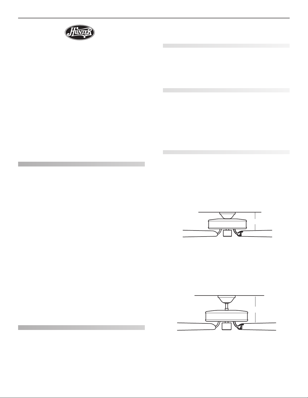
Standard Mounting (Figure 2) hangs from the ceiling by a downrod
(included), for ceilings 8 feet or higher. For ceilings higher than 8
feet, you can purchase Hunter extension downrods. All Hunter
fans use sturdy 3/4" diameter pipe to assure stability and wobblefree performance.
®
10”
12”
getting ready
To install a ceiling fan, be sure you can do the following:
• Locate the ceiling joist or other suitable support in ceiling.
• Drill holes for and install wood screws.
• Identify and connect electrical wires.
• Lift 40 pounds.
41857-01 02/22/2005 © 2005 Hunter Fan Company
Figure 2 - Standard mounting
3
Angle Mounting (Figure 3) hangs from a vaulted or angled ceiling.
34º Max
8
Pitch
12
Figure 3 - Angle mounting
preparing the fan site
These guidelines are designed to help you select the best location
for your fan and to prepare the site prior to installing the fan. Proper
ceiling fan location and attachment to the building structure are
essential for safety, reliable operation, maximum efficiency, and energy savings.
choosing the fan site
Within the room where you want to install the fan, choose a fan
site where:
• No object can come in contact with the rotating fan blades
during normal operation.
• The fan blades are at least 7 feet above the floor and the
ceiling is at least 8 feet high.
• The fan blades have no obstructions to air flow, such as
walls or posts, within 30 inches of the fan blade tips.
• The fan is directly below a joist or support brace that will
hold the outlet box and the full weight of the fan.
See Figure 4 for the minimum mounting distances.
using an existing fan site
If you are preparing a new fan site, go to the preparing a new fan
site section.
If you plan to use an existing fan site, complete the following checklist for the support brace, ceiling hole, outlet box, and wiring. If you
cannot check off every item, see the preparing a new fan site sec-
tion for instructions on properly preparing the site for your new
fan.
fan support system
• Fan must attach directly to building structure.
• Fan support system must hold full weight of fan and light
kit.
ceiling hole
• Outlet box clearance hole directly below the joist or support brace.
outlet box
• UL-approved octagonal 4" x 1-1/2" outlet box (or as specified by the support brace manufacturer).
• Outlet box secured to joist or support brace by wood
screws and washers through inner holes of outlet box.
• Outer holes of outlet box aligned with joist or support
brace.
• Bottom of outlet box recessed a minimum of 1/16" into
ceiling.
wiring
• Electrical cable secured to outlet box by approved connector.
• Six inches of lead wires extend from outlet box.
See Figure 5 for an adequate existing fan site.
Support Brace
Ceiling Joist
Approved
Connector
30” From
8’ Minimum
Ceiling Height
7’ Minimum
to Floor
Wall or
Nearest
Obstruction
Washer
Wood Screw
Figure 5 - Adequate existing fan site
Outlet Box
Ceiling
If your existing fan site is suitable, go to the installing the ceiling
plate section and begin installing your new Hunter fan.
Figure 4 - Minimum mounting distances
preparing a new fan site
To prepare the fan site follow four steps:
• Cutting the Ceiling Hole
• Installing the Support Brace (if necessary)
• Installing the Outlet Box
• Preparing the Wiring
© 2005 Hunter Fan Company 41857-01 02/22/2005

4
cutting the ceiling hole
1. Locate the site for the hole directly below the joist or support
brace that will hold the outlet box and fan.
2. Cut a 4" diameter hole through the drywall or plaster of the
ceiling as shown in Figure 6. You will use the hole to install the
support brace and outlet box.
Support Brace
Figure 6 - Cutting the ceiling hole
Ceiling Joist
4”
Diameter
Ceiling
Hole
Ceiling
installing the support brace
If there is a ceiling joist directly above the hole which will allow the
outlet box to be recessed a minimum of 1/16" in the ceiling, go to
installing the outlet box section.
If there is not an adequate ceiling joist available, do the following:
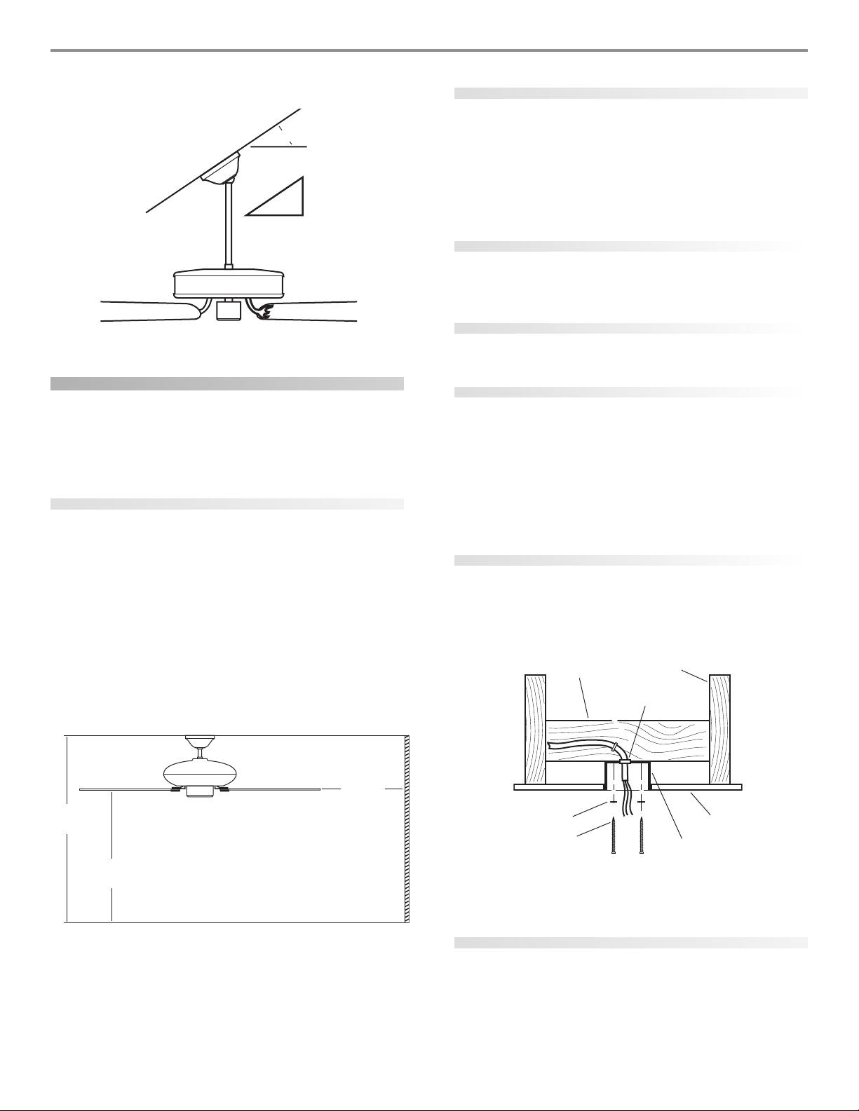
1. Attach a 2" x 4" support brace between two joists. The support brace must allow the bottom of the outlet box to be recessed a minimum of 1/16" into the ceiling. See Figure 7.
2. Check the support brace to ensure it will support the full weight
of the fan and light kit.
installing the outlet box
1. Obtain a UL-approved octagonal 4" x 1-1/2" outlet box, plus
two #8 x 1-1/2" wood screws and washers, available from any
hardware store or electrical supply house.
2. Orient the outlet box so that both the inner and outer holes in
the box align with the joist or support brace.
3. Drill pilot holes no larger than the minor diameter of the wood
screws (5/64") through the inner holes of the outlet box.
4. Attach the outlet box directly to the support brace or joist
with two #8 x 1-1/2" wood screws and washers. The bottom of
the outlet box must be recessed a minimum of 1/16" into the
ceiling as shown in Figure 7.
Support Brace
preparing the wiring
CAUTION: All wiring must be in accordance with national and local electrical codes and ANSI/NFPA 70. If you
are unfamiliar with wiring, you should use a qualified electrician.
1. Make sure the circuit breakers to the fan supply line leads and
associated wall switch location are turned off. If you cannot
lock the circuit breakers in the off position, securely fasten a
prominent warning device, such as a tag, to the service panel.
2. Thread the fan supply line through the outlet box so that the
fan supply line extends at least 6" beyond the box as shown in
Figure 8.
3. Attach the fan supply line to the outlet box with an approved
connector, available at any hardware store or electrical supply
house. Refer to Figure 8.
4. Make certain the wiring meets all national and local standards
and ANSI/NFPA 70.
Approved
Connector
Wire Leads
Figure 8 - Preparing the wiring
You have now successfully prepared your ceiling fan site. For instructions on how to install your ceiling fan, continue with the in-
stalling the ceiling plate section.
installing the ceiling plate
1. Drill two pilot holes into the wood support structure through
the outermost holes on the outlet box. The pilot holes should
be 9/64" in diameter.
2. Thread the lead wires from the outlet box through the hole in
the middle of the ceiling plate.
3. Your fan comes with four neoprene noise isolators. Position
the isolators between the ceiling plate and ceiling by inserting
the raised areas on each isolator into the holes in the ceiling
plate. Refer to Figure 9.
Isolators
Washer
Wood Screw
Figure 7 - Installing the outlet box
41857-01 02/22/2005 © 2005 Hunter Fan Company
Outlet Box
1/16” Recess
Ceiling Plate
Figure 9 - Inserting the isolators into the ceiling plate
 Loading...