

Page 1

Installation and Operation Manual
For Hunter Ceiling Fans
®
41545-01 6/10/2002
41545-01 6/10/2002
1
Page 2

®
41545-01 6/10/2002
2
Page 3

CONGRATULATIONS!
Your new Hunter ceiling fan is an
addition to your home or office that
will provide comfort and performance for many years. This manual
gives you complete instructions for
installing and operating your fan.
We are proud of our work. We appreciate the opportunity to supply
you with the best ceiling fan available anywhere in the world.
Before installing your fan, record the
following information for your
records and warranty assistance.
Please refer to the carton and the
Hunter nameplate (located on top
outside fan motor housing) for the
proper information.
Model Name __________________
Catalog No. ___________________
Serial No. _____________________
Date Purchased ________________
Where Purchased ______________
_____________________________
®
Attach Your Receipt
or a Copy of
Your Receipt Here
41545-01 6/10/2002
© 2002 Hunter Fan Co.
6/2002
3
Page 4

®
CONTENTS
CONGRATULATIONS! ......................................................................................................................................... 3
IMPORTANT INFORMATION ................................................................................................................................5
STEP 1 - GETTING READY ................................................................................................................................... 6
STEP 2 - INSTALLING THE CEILING PLATE ............................................................................................................8
STEP 3 - ASSEMBLING HOUSINGS..................................................................................................................... 10
STEP 4 - ASSEMBLING THE FAN ........................................................................................................................ 11
STEP 5 - WIRING THE FAN ................................................................................................................................ 13
STEP 6 - HANGING THE FAN ............................................................................................................................. 15
STEP 7 - ASSEMBLING FAN BLADES .................................................................................................................. 16
STEP 8 - ATTACHING THE SWITCH HOUSING ................................................................................................... 18
STEP 9 - INSTALLING LIGHT FIXTURE .................................................................................................................20
OPERATING YOUR HUNTER FAN ....................................................................................................................... 21
CLEANING AND MAINTENANCE ....................................................................................................................... 23
TROUBLESHOOTING ......................................................................................................................................... 24
41545-01 6/10/2002
4
Page 5
IMPORTANT INFORMATION
®
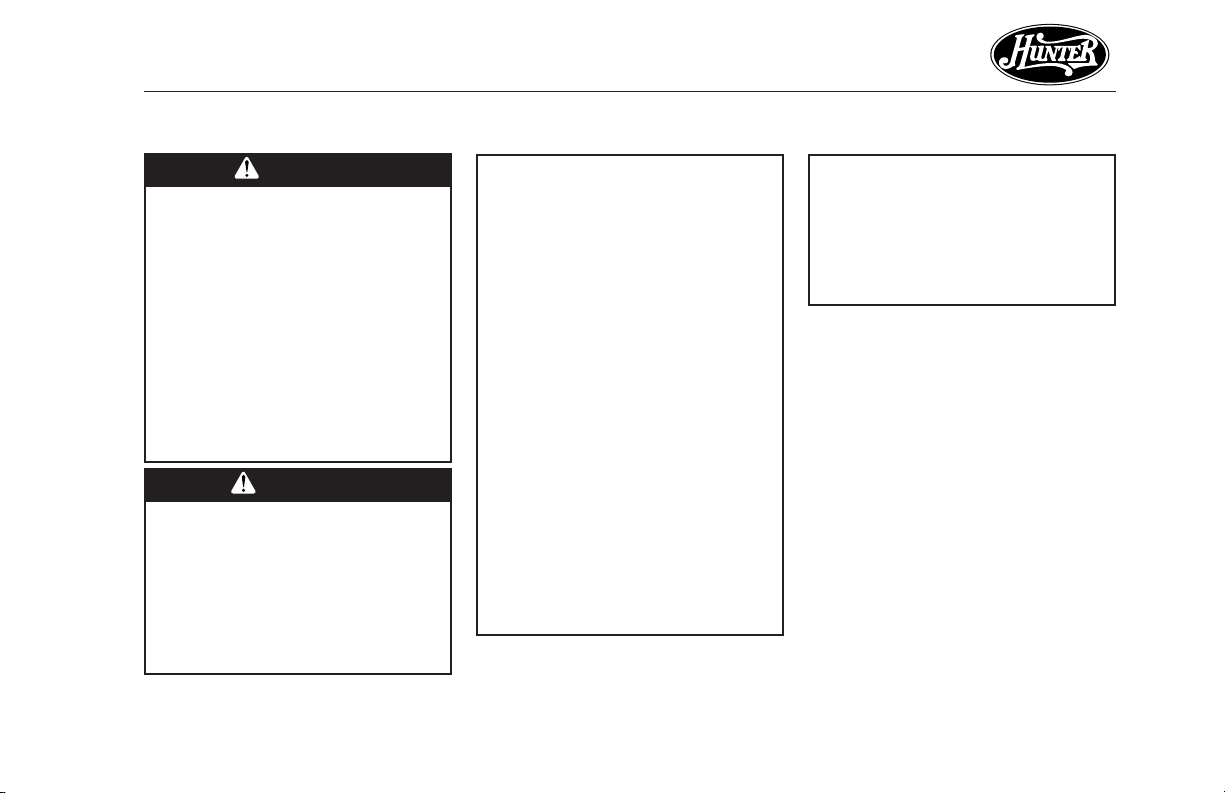
CAUTIONS
• Read entire booklet carefully
before beginning installation
and save these instructions.
• To reduce the risk of personal
injury, attach the fan directly
to the support structure of the
building according to these instructions, and use only the
hardware supplied.
WARNINGS
• To avoid possible electrical
shock, before installing
your fan, disconnect the
power by turning off the
circuit breakers to the outlet box and associated wall
switch location. If you can-
41545-01 6/10/2002
not lock the circuit breakers
in the off position, securely
fasten a prominent warning
device, such as a tag, to the
service panel.
• All wiring must be in accordance with national and local electrical codes and
ANSI/NFPA 70. If you are
unfamiliar with wiring, you
should use a qualified electrician.
• To reduce the risk of personal injury, do not bend
the blade attachment system when installing, balancing, or cleaning the fan.
Never insert foreign objects
between rotating fan
blades.
• To reduce the risk of fire, electrical shock, or motor damage, do not use a solid-state
speed control with this fan.
Use only Hunter speed controls.
DO YOU NEED HELP?
To install a ceiling fan, be sure you
can do the following:
• Locate ceiling joist or other suitable support in ceiling.
• Drill holes for and install wood
screws.
• Identify and connect electrical
wires.
• Lift 40 pounds.
If you need help installing the fan,
your Hunter fan dealer can direct you
to a licensed installer or electrician.
5
Page 6

®
STEP 1 - GETTING READY
GATHERING THE TOOLS
You will need the following tools for
installing the fan:
• Electric drill with 9/64" bit
• Standard screwdriver
• Phillips-head screwdriver
• Wrench or pliers
OPTIONAL ACCESSORIES
Consider using Hunter’s optional accessories, including a wall-mounted
or remote speed control. To install and
use the accessories, follow the instructions included with each product.
For quiet and optimum performance
of your Hunter fan, use only Hunter
speed controls.
PREPARING THE FAN SITE
The location of a ceiling fan and how
the fan is attached to the building
structure are essential for reliable
operation, maximum efficiency, and
energy savings. For this reason, we
have included a separate booklet —
“Guide to Choosing and Preparing
a Ceiling Fan Site” — to help you
select the best location for your fan.
The booklet also provides information to ensure your fan support and
electric outlet box meet UL-approved
safety codes for ceiling fans.
The instructions in this installation
manual assume that you have used
“Guide to Choosing and Preparing
a Ceiling Fan Site” to pick the fan
location and make certain the proper
fan support and outlet box are installed.
CHECKING YOUR FAN PARTS
Carefully unpack your fan to avoid
damage to the fan parts. Check for
any shipping damage to the motor
or fan blades. If one of the fan blades
was damaged in shipment, return all
the blades for replacement.
Hint: If you are installing more than
one fan, keep the fan blades
in sets, as they were shipped.
The fan includes a separate diagram
of the screws and other small parts
needed for the fan. Keep this diagram handy for identifying parts during installation; the diagram indicates
the step in which each part is used.
If any parts are missing or damaged,
contact your Hunter dealer or call
Hunter Parts Department at
901-248-2222.
41545-01 6/10/2002
6
Page 7
®
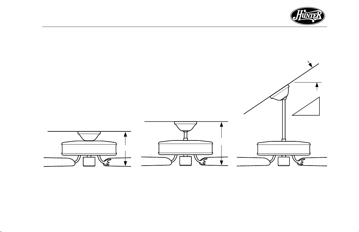
34° Max
Pitch
12
8
INSTALLER’S CHOICE®
This patented 3-position mounting
system provides you maximum installation flexibility and ease. You can
install your Hunter fan in one of three
ways. The steps in this manual include specific instructions for the fan
mounting method of your choice. For
a ceiling 8 feet or higher, standard
mounting is recommended.
10"
Figure 1a - Flush Mounting
Flush Mounting (Figure 1a) fits close
to the ceiling, for low ceilings less
than 8 feet high.
Standard Mounting (Figure 1b) hangs
from the ceiling by a connector pipe
(included), for ceilings 8 feet or
higher. For ceilings higher than eight
feet, you can purchase Hunter extension rods. All Hunter fans use
sturdy 3/4" diameter pipe to assure
stability and wobble-free performance.
12"
Figure 1b - Standard Mounting
Angle Mounting (Figure 1c) hangs
from a vaulted or angled ceiling.
Figure 1c - Angle Mounting
41545-01 6/10/2002
7
Page 8
®
STEP 2 - INSTALLING THE CEILING PLATE
1. Drill two pilot holes into the wood
support structure through the
outermost holes on the outlet
box. The pilot holes should be
9/64" in diameter.
2. Thread the lead wires from the
outlet box through the hole in the
middle of the ceiling plate.
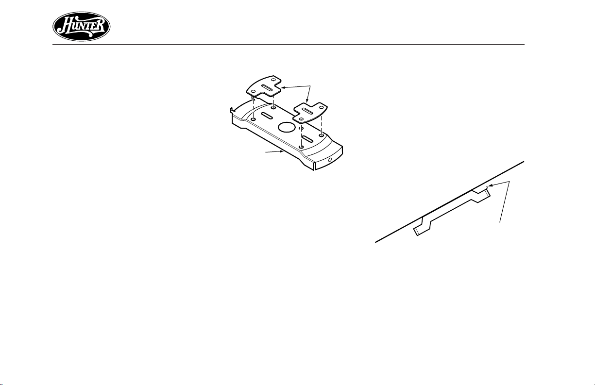
3. Your fan comes with two neoprene noise isolators. Position the
isolators between the ceiling plate
and ceiling by inserting the raised
areas on each isolator into the
holes in the ceiling plate. Refer to
Figure 2a.
Isolators
Ceiling
Plate
Figure 2a - Adding Isolators to Ceiling
Plate
4. Align the slotted holes in the ceiling plate with the pilot holes in
the wood support structure.
Note: The isolation pads should
be flush against the ceiling.
For Angle Mounting Only: Be
sure to orient the ceiling plate so
that the two hooks point up towards the ceiling peak as shown
in Figure 2b. Note: You will use
the hooks to support the fan during STEP 5 - WIRING THE FAN.
Figure 2b - Correct Position of Ceiling
Plate for Angle Mounting
Ceiling Plate
Hooks
41545-01 6/10/2002
8
Page 9

5. Place a flat washer on each of the
two 3" screws and pass the
screws through the slotted holes
in the ceiling plate as shown in
Figure 2c.
6. Tighten the screws into the 9/64"
pilot holes; do not use lubricants
on the screws. Do not overtighten.
Ceiling Joist
2 x 4 Brace
®
Ceiling
Plate
Flat
Washer
Figure 2c - Attaching Ceiling Plate to
2 x 4 Brace
41545-01 6/10/2002
Ceiling
Outlet Box
3" Wood
Screw
9
Page 10

®
STEP 3 - ASSEMBLING HOUSINGS
Some fans are shipped with the
decorative upper and lower housings
detached from the fan motor. This
step tells you how to attach the housing. If the housing for your fan is already attached to the fan motor, go
directly to STEP 4 - ASSEMBLING THE
FAN.
1. Fit the upper fan housing on the
motor hanger adapter. Make sure
Upper Housing
Notches
Motor Hanger
Adaptor Tab
the tabs in the motor hanger
adapter fit into the notches in the
upper housing as shown in Figure 3a.
2. Attach the upper fan housing to
the motor hanger adapter with
three 1/2" screws and lockwashers as shown in Figure 3b.
Motor Hanger
Upper Fan
Housing
Bottom Cover
Adaptor
Acorn Nut
Washer
Thrubolt
3. Attach the bottom cover to the
upper fan housing with thrubolts
and acorn nuts as shown in Figure 3b, or with #6-32 screws and
lockwashers as shown in Figure
3c – depending upon style of fan.
Upper Fan
Housing
#6-32 Screw
with Lockwasher
Bottom Cover
Figure 3a - Motor Hanger Adapter
Tabs and Upper Housing Notches
10
Figure 3b - Assembling and Attaching
Housings to Motor Hanger Adapter
Figure 3c - Attaching Bottom Cover to
Upper Fan Housing
41545-01 6/10/2002
Page 11

STEP 4 - ASSEMBLING THE FAN
Use the Step 4 instructions for the
type of mounting you have selected:
standard, angle, or flush.
STANDARD AND ANGLE
MOUNTING
For Standard 8-foot Ceilings and
Higher
1. Insert the pipe through the
canopy as shown in Figure 4a.
Pipe
Canopy
Pipe
Setscrew
Figure 4a - Inserting Pipe through
Canopy
41545-01 6/10/2002
Feed wires from the fan through
the pipe.
2. Screw pipe into fan assembly un-
til tight. IMPORTANT! Tighten
pipe setscrew as shown in Figure
4a.
CAUTION
The pipe has a special coating on
the threads. Do not remove this
coating; the coating prevents the
pipe from unscrewing. Once assembled, do not remove the pipe.
FLUSH MOUNTING
For Low Ceilings
1. Fit the canopy over the motor
hanger adapter as shown in Figure 4b. Make sure the canopy fits
snugly against the fan assembly
®
with no space between the
pieces.
2. You will find a large assembly
washer included with the fan.
Place the washer over the adapter
and canopy as shown in Figure
4b.
Assembly
Washer
Canopy
Adapter
Top of Fan
Figure 4b - Placing Canopy and
Washer Over Adapter
continued
11
Page 12

®
3. Position the slots in the assembly washer over the threaded
holes in the adapter as shown
in Figure 4c.
Adapter
Assembly
Washer
Figure 4c - Positioning Assembly
Washer Slots over Threaded Holes
Threaded
Hole
4. Attach the canopy tightly to the
fan assembly with three #8-32
assembly screws and lockwashers
as shown in Figure 4d.
Assembly Screw
and Lockwasher
Figure 4d - Attaching Canopy to Fan
Assembly
12
41545-01 6/10/2002
Page 13

STEP 5 - WIRING THE FAN
1. Disconnect the power by turning
off the circuit breakers to the outlet box and associated wall switch
location.
2. Tilt and hang the assembled fan
from the ceiling plate hooks. Slip
two rectangular canopy slots over
ceiling plate hooks as shown in
Figures 5a and 5b.
Figure 5a - Attaching Slots on Canopy
to Ceiling Plate Hooks
41545-01 6/10/2002
Note: To hang the fan you must
tilt the canopy to an almost vertical position so the canopy slots
come down over the ceiling plate
hooks.
Figure 5b - Assembled Fan Hanging
from Ceiling Plate Hooks
Ceiling
Plate
®
3. You can use either one or two
wall switches to control the fan
and/or lights separately. Use connection 1 on page 14 to
• control the light with a wall
switch and the fan with a
chain pull (one wall switch required)
• control the light with a chain
pull and the fan with a wall
switch (one wall switch required)
• control the light with one wall
switch and the fan with another (two wall switches required)
Use connection 2 on page 14 if
there is no separate wall switch
power wire for the light fixture.
Note: Wall switches not included.
continued
13
Page 14

®
4. Connect the wires as shown in
Figure 5c. To connect the wires,
twist the bare metal leads together. Place a wire nut over the
intertwined length of wire and
twist clockwise until tight as
shown.
CAUTION
Be sure no bare wire or wire
strands are visible after making connections.
Wall Switch Wire For
Separate Control of Light Fixture
In
Bare or Green
Black
White
Power
Wires
Ceiling
2 x 4 Brace
(Note: Wall switch
must be acceptable
as a general-use
switch.)
Outlet Box
5. Separate the connected wires by
placing the green and white wires
on one side of the outlet box and
the black and the black/white
wires on the other side of the
outlet box.
6. Turn the connectors upward. Push
the wires gently into the outlet
box.
14
Green
Approved
Connectors
Green Ground
Wire from Hanger
Pipe (not present
with flush mounting
option)
Black
White
2
Ceiling
1
Black/White
3 Wires
From Fan
Plate
Connections:
Connect Blk/Wht Wire from fan
1
to Wall Switch Wire for separate
control of light fixture, or
Connect Blk/Wht Wire from fan
2
to Ceiling Black Wire if there
is no separate Wall Switch Wire
for the light fixture.
Figure 5c - Wiring Diagram
41545-01 6/10/2002
Page 15

STEP 6 - HANGING THE FAN
Sub-steps 1 and 2 apply to Flush,
Standard, and Angle mounting. Substep 3 applies to Standard and Angle
mounting only.
1. Swing the fan up so as to align
the canopy screw holes with the
mounting holes on the ceiling
plate. Refer to Figure 6a.
Ceiling
Plate
Canopy
2. Install and tighten the two #1032 x 1/2" mounting screws.
3. For Standard and Angle
Mounting only: In addition to
sub-steps 1 and 2, lift the fan
housing towards the ceiling and
rotate the fan until each canopy
tab engages a groove in the
hanger ball as shown in Figure 6b.
Note: If the tabs are already engaged, do not rotate.
WARNING
Failure to complete sub-steps 1
through 3 could cause fan to fall.
(Sub-step 3 not applicable for
flush mounting.)
®
Groove in
Hanger Ball
Groove in
Hanger
Ball
Canopy
Tab
Figure 6b - Canopy Tabs and Grooves
in Hanger Ball
Figure 6a - Attaching Canopy to
Ceiling Plate
41545-01 6/10/2002
continued
15
Page 16

®
STEP 7 - ASSEMBLING FAN BLADES
Hunter fans use several styles of fan
blade irons (brackets that hold the
blade to the fan).
1. Your fan may include blade grommets (see Parts List). If your fan
has grommets, insert them by
hand into the holes as shown in
Figure 7a.
2. Attach each blade to blade iron
using three blade assembly screws
as shown in Figure 7b. Some fans
Grommet
Fan
Blade
feature a decorative medallion as
well as a blade iron. Insert the
assembly screws into the blade
iron, through the blade and into
the medallion, with the blade
sandwiched between the blade
iron and medallion as shown in
Figure 7c.
If you used grommets, the blades
may appear slightly loose after
screws are tightened. This is normal.
3. Remove the blade mounting
screws and rubber shipping
bumpers from the motor.
Blade
Iron
Medallion
Figure 7a - Inserting Grommet into
Fan Blade
16
Figure 7b - Attaching Fan Blade to
Blade Iron
Figure 7c - Attaching Fan Blade to
Blade Iron using Decorative Medallion
41545-01 6/10/2002
Page 17

4. For each blade, insert one blade
mounting screw through the
blade iron as shown in Figure 7d,
and attach lightly to the fan. Insert the second blade mounting
screw, then securely tighten both
mounting screws.
Figure 7d - Attaching Blade Irons to
Hub of Fan Assembly
®
41545-01 6/10/2002
17
Page 18

®
STEP 8 - ATTACHING THE SWITCH HOUSING
The switch housing is made up of
two sections: the upper switch housing, and the lower switch housing.
ATTACHING THE UPPER SWITCH
HOUSING
1. Partially install two #6-32 x 3/8"
housing assembly screws into the
switch housing mounting plate as
shown in Figure 8a.
Switch
Housing
Mounting
Plate
Upper
Switch
Housing
Figure 8a - Attaching Upper Switch
Housing to Switch Housing Mounting
Plate
Housing
Assembly
Screw
Upper Plug
Connector
2. Feed the upper plug connector
through the center opening of the
upper switch housing. See Figure
8a.
3. Align the keyhole slots in the upper switch housing with the housing assembly screws installed in
sub-step 1.
4. Turn the upper switch housing
counterclockwise until the housing assembly screws are firmly
situated in the narrow end of the
keyhole slots as shown in Figure
8b. Install the one remaining #632 x 3/8" housing assembly screw
into the third hole in the upper
switch housing. Tighten all three
screws firmly.
Make sure the upper switch housing is securely attached to the
switch housing mounting plate.
Failure to properly attach and
tighten all three housing assembly screws could result in the
switch housing and light fixture
falling.
Figure 8b - Mounting the Upper
Switch Housing
CAUTION
18
41545-01 6/10/2002
Page 19

®
5. Connect the upper plug connector from the motor to the lower
plug connector in the lower
switch housing assembly. See Figure 8c.
Note: Both plug connectors are
polarized and will only fit together
one way. Make sure that both
connectors are properly aligned
before connecting them together.
Incorrect connection could cause
improper operation and damage
to the product.
6. Place the lower switch housing
assembly over the upper switch
housing. Align the side screw
holes in the upper and lower
switch housings. Attach the lower
switch housing to the upper
switch housing with three #6-32
x 3/8" housing assembly screws.
See Figure 8c.
Upper
Switch
Housing
Lower Plug
Connector
Housing
Assembly
Screw
Figure 8c - Plug Connection and Lower
Switch Housing Installation
Upper Plug
Connector
Lower
Switch
Housing
Note: If your fan does not include
a light fixture, you may purchase
an accessory light kit separately.
See STEP 9 - INSTALLING LIGHT
FIXTURE.
41545-01 6/10/2002
19
Page 20

®
STEP 9 - INSTALLING LIGHT FIXTURE
INSTALLING ACCESSORY LIGHT
KITS
To install the light kit, follow the instructions included with the kit for
wiring, mounting, and assembly.
20
41545-01 6/10/2002
Page 21

OPERATING YOUR HUNTER FAN
Pull
Chain
Reversing
Switch
1. Turn on electrical power to the
fan.
2. The pull chain controls power to
the fan. The chain has four settings in sequence: High, Medium,
Low and Off.
• Pull the chain slowly to change
settings.
• Release slowly to prevent the
chain from recoiling into the
blades.
• The chain uses a breakaway
connector that separates if the
chain is jerked. If this happens,
simply reinsert the chain into
the connector.
3. Ceiling fans work best by blowing air downward (counterclockwise blade rotation) in warm
weather to cool the room with a
direct breeze. In winter, having
the fan draw air upward (clockwise blade rotation) will distribute the warmer air trapped at the
ceiling around the room without
causing a draft.
Figure 10a - Air Flow Patterns
To change the direction of air
flow, turn the fan off and let it
come to a complete stop. Slide
the reversing switch on the fan
to the opposite position as shown
in Figure 10b. Restart fan.
®
Figure 10b - Pull Chain and Reversing
Switch
4. If your fan wobbles when operating, use the enclosed balancing
kit and instructions to balance the
fan.
41545-01 6/10/2002
21
Page 22

®
Hunter fans have the
power to cut your cooling
costs up to 40%.
Beat the High Cost of Cooling
The air movement created by a
Hunter ceiling fan lets you set your
thermostat higher and still stay comfortable. Every degree you raise the
thermostat saves up to 7% on energy costs. So, you can cut back on
expensive air conditioning...and save
up to 40%* on cooling. In winter,
your Hunter fan recirculates warm air
and saves up to 10%* on heating
bills.
*Your savings many vary based on climate,
building type and thermostat setting. On
average at low speed settings.
Save Energy and Money While
Protecting the Environment
Congratulations! You're saving energy
and money while protecting the environment by purchasing this ENERGY STAR
qualified Hunter ceiling fan! With this
purchase, you are doing your part to
protect the environment. In 2010,
ENERGY STAR qualified ceiling fans
are projected to cut air pollution by
more than 500 million pounds!
Your new ceiling fan has earned the
ENERGY STAR label because it meets
high energy efficiency specifications
set by the Environmental Protection
Agency (EPA). ENERGY STAR labeled
ceiling fans save energy because
they have more efficient fan motors
and air delivery due to more aerodynamic blade configurations. Ceiling
fan models bearing the ENERGY STAR
label move air 14 - 20% more efficiently than typical ceiling fan models. For more information on ENERGY
STAR visit www.energystar.gov.
22
41545-01 6/10/2002
Page 23

CLEANING AND MAINTENANCE
Caring for finishes: For cleaning, a
soft brush or lint-free cloth should
be used to prevent scratching the finish. A vaccuum cleaner brush nozzle
can remove heavier dust. Surface
smudges or an accumulation of dirt
and dust can easily be removed by
using a mild detergent and a slightly
dampened cloth. An artistic agent
may be used, but never use abrasive
cleaning agents as they will damage
the finish.
Caring for blades: Wood finish
blades should be cleaned with a furniture polishing cloth. Occasionally,
a light coat of furniture polish may
be applied for added protection and
beauty. Painted and high-gloss
blades may be cleaned in the same
manner as the fan finish.
®
MANUFACTURER'S
PHONE NUMBER
If you need parts or service
asssitance, please call 901-248-2222
or visit us at our WEB site at:
http://www.hunterfan.com
41545-01 6/10/2002
23
Page 24

®
TROUBLESHOOTING
PROBLEM PROBABLE CAUSE SOLUTION
Nothing happens; fan does not move.
1. Power turned off, fuse blown, or
circuit breaker tripped.
2. Loose wire connections or wrong
connections.
3. Motor reversing switch not engaged.
4. Pull chain switch not “on.”
5. Shipping bumpers still in place.
1. Turn power on, replace fuse, or reset breaker.
2a. Loosen canopy, check all connections
according to STEP 5 - WIRING THE
FAN (turn power off before
checking).
2b.Check the plug connection in the
switch housing according to STEP
8-ATTACHING THE SWITCH HOUSING.
3. Push switch firmly up or down.
4. Pull switch chain.
5. Remove shipping bumpers.
Noisy operation.
24
1. Blade brackets screwed loosely to
motor.
2. Blade screwed loosely to blade iron.
3. Blade cracked.
1. Tighten screws until snug.
2. Tighten screws until snug.
3. Replace all blades.
41545-01 6/10/2002
Page 25

PROBLEM PROBABLE CAUSE SOLUTION
Noisy operation (continued).
4. Using non-approved speed control.
5. Glass screwed loosely to fixture.
4. Change to approved speed control.
5. Hand-tighten the light fixture
screws. Ensure that rubber noise
isolators are installed.
6. Switch housing is loose.
6. Check and tighten screws to the
switch housing mounting plate and
to the upper and lower switch
housing.
®
Excessive wobbling.
Note: When switching from medium
to low speed, you may notice some fan
wobble. When the fan stabilizes at low
speed, wobble will disappear.
1. Unbalanced blades.
2. Loose blades or blade irons.
3. Fan not secure on hanger assembly.
4. Fan hanger ball not seated in
canopy tabs.
1. Use balancing kit included with fan.
2. Tighten all screws.
3. Turn power off, support fan very
carefully, loosen canopy and hang
correctly.
4. Turn power off, support the fan
very carefully, and check that the
hanger ball is properly seated.
If you have tried these troubleshooting solutions and still have trouble, call 901-248-2222 or visit our
Web site at http://www.hunterfan.com.
41545-01 6/10/2002
25
 Loading...