

Page 1

Installation and Operation Manual
For Hunter Ceiling Fans
®
41462-01 10/14/2005
41462-01 10/14/2005
1
Page 2

®
41462-01 10/14/2005
2
Page 3

®
CONGRACONGRA
CONGRA
CONGRACONGRA
Your new Hunter ceiling fan is an
addition to your home or office that
will provide comfort and performance for many years. This manual
gives you complete instructions for
installing and operating your fan.
We are proud of our work. We appreciate the opportunity to supply
you with the best ceiling fan available anywhere in the world.
Before installing your fan, record the
following information for your
records and warranty assistance.
Please refer to the carton and the
Hunter nameplate (located on top
outside fan motor housing) for the
proper information.
41462-01 10/14/2005
TULATULA
TULA
TULATULA
TIONS!TIONS!
TIONS!
TIONS!TIONS!
Model Name ___________________
Catalog No. ___________________
Serial No.______________________
Date Purchased _________________
Where Purchased _______________
Attach Your Receipt
or a Copy of
Your Receipt Here
© 2005 Hunter Fan Co.
10/14/2005
3
Page 4

®
CONTENTSCONTENTS
CONTENTS
CONTENTSCONTENTS
Important Information .......................................................................................................................... 5
Step 1 - Getting Ready .......................................................................................................................... 6
Step 2 - Installing The Ceiling Plate ........................................................................................................ 8
Step 3 - Assembling The Fan ................................................................................................................ 10
Step 4 - Hanging The Fan .................................................................................................................... 11
Step 5 - Wiring The Fan ....................................................................................................................... 12
Step 6 - Attaching The Canopy ............................................................................................................ 14
Step 7 - Assembling Fan Blades ............................................................................................................ 15
Step 8 - Attaching The Switch Housing ................................................................................................ 16
Step 9 - Remote Control ...................................................................................................................... 18
Operating Your Hunter Fan ................................................................................................................. 22
Cleaning And Maintenance ................................................................................................................. 23
Troubleshooting .................................................................................................................................. 24
41462-01 10/14/2005
4
Page 5

®
IMPORIMPOR
IMPOR
IMPORIMPOR
• Read entire booklet carefully before beginning installation and save these
instructions.
• To reduce the risk of personal injury, attach the fan
directly to the support
structure of the building according to these instructions, and use only the
hardware supplied.
• Do not hang fan on ceilings
that have a height less than
9 feet.
• To avoid possible electrical
shock, before installing
your fan, disconnect the
power by turning off the
circuit breakers to the out-
TT
ANT INFORMAANT INFORMA
T
ANT INFORMA
TT
ANT INFORMAANT INFORMA
CAUTIONSCAUTIONS
CAUTIONS
CAUTIONSCAUTIONS
WARNINGSWARNINGS
WARNINGS
WARNINGSWARNINGS
TIONTION
TION
TIONTION
let box and associated wall
switch location. If you cannot lock the circuit breakers
in the off position, securely
fasten a prominent warning
device, such as a tag, to the
service panel.
• All wiring must be in accordance with national and local electrical codes and
ANSI/NFPA 70. If you are
unfamiliar with wiring, you
should use a qualified electrician.
• To reduce the risk of personal injury, do not bend
the blade attachment system when installing, balancing, or cleaning the fan.
Never insert foreign objects
between rotating fan
blades.
• To reduce the risk of fire,
electrical shock, or motor
damage, do not use a solidstate speed control with this
fan. Use only Hunter speed
controls.
DO YOU NEED HELP?DO YOU NEED HELP?
DO YOU NEED HELP?
DO YOU NEED HELP?DO YOU NEED HELP?
To install a ceiling fan, be sure you
can do the following:
• Locate ceiling joist or other suitable support in ceiling.
• Drill holes for and install wood
screws.
• Identify and connect electrical
wires.
• Lift 40 pounds.
If you need help installing the fan,
your Hunter fan dealer can direct you
to a licensed installer or electrician.
41462-01 10/14/2005
5
Page 6

®
STEP 1 - GETTING READYSTEP 1 - GETTING READY
STEP 1 - GETTING READY
STEP 1 - GETTING READYSTEP 1 - GETTING READY
GAGA
THERING THE TOOLSTHERING THE TOOLS
GA
THERING THE TOOLS
GAGA
THERING THE TOOLSTHERING THE TOOLS
You will need the following tools for
installing the fan:
• Electric drill with 9/64" bit
• Standard screwdriver
• Phillips-head screwdriver
• Wrench or pliers
PREPPREP
ARING THE FAN SITEARING THE FAN SITE
PREP
ARING THE FAN SITE
PREPPREP
ARING THE FAN SITEARING THE FAN SITE
Ceiling height must be a minimum
of 9 feet.
The location of a ceiling fan and
how the fan is attached to the building structure are essential for reliable operation, maximum efficiency, and energy savings. For this
reason, we have included a separate booklet — “Guide to Choosing and Preparing a Ceiling Fan
Site” — to help you select the best
location for your fan. The booklet
also provides information to ensure
your fan support and electric outlet box meet UL-approved safety
codes for ceiling fans.
The instructions in this installation
manual assume that you have used
“Guide to Choosing and Preparing
a Ceiling Fan Site” to pick the fan
location and make certain the proper
fan support and outlet box are installed.
CHECKING YOUR FAN PARCHECKING YOUR FAN PAR
CHECKING YOUR FAN PAR
CHECKING YOUR FAN PARCHECKING YOUR FAN PAR
Carefully unpack your fan to avoid
damage to the fan parts. Check for
any shipping damage to the motor
or fan blades. If one of the fan blades
was damaged in shipment, return all
the blades for replacement.
TSTS
TS
TSTS
Hint: If you are installing more than
one fan, keep the fan blades
in sets, as they were shipped.
If any parts are missing or damaged,
contact your Hunter dealer or call
Hunter Parts Department at
901-248-2222.
41462-01 10/14/2005
6
Page 7
®
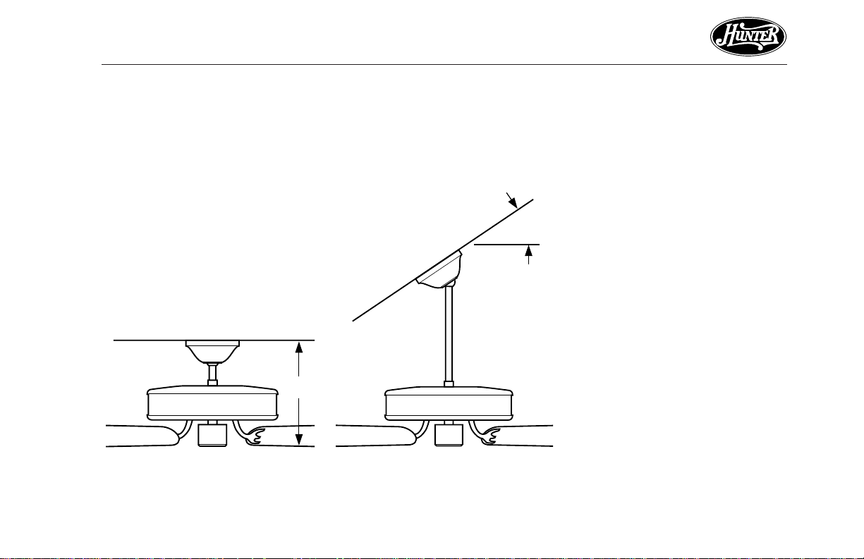
Standard MountingStandard Mounting
Standard Mounting (Figure 1a)
Standard MountingStandard Mounting
hangs from the ceiling by a connector pipe (included), for ceilings 9
feet or higher. For ceilings higher
than nine feet, you can purchase
Hunter extension rods. All Hunter
fans use sturdy 3/4" diameter pipe
to assure stability and wobble-free
performance.
15.65"
12"
Figure 1a - Standard MountingFigure 1a - Standard Mounting
Figure 1a - Standard Mounting
Figure 1a - Standard MountingFigure 1a - Standard Mounting
Angle MountingAngle Mounting
Angle Mounting
Angle MountingAngle Mounting
(Figure 1b)
hangs from a vaulted or angled ceiling.
29° Max
34° Max
Pitch
8
12
Figure 1b - Angle MountingFigure 1b - Angle Mounting
Figure 1b - Angle Mounting
Figure 1b - Angle MountingFigure 1b - Angle Mounting
41462-01 10/14/2005
7
Page 8

®
STEP 2 - INSTSTEP 2 - INST
STEP 2 - INST
STEP 2 - INSTSTEP 2 - INST
WW
ARNINGARNING
W
ARNING
WW
ARNINGARNING
• To avoid possible electrical
shock, before wiring fan,
disconnect power by turning off the circuit breakers
both to the outlet box and
to its associated wall switch
location. If you cannot lock
the circuit breakers in the
off position, securely fasten
a prominent warning device, such as a tag, to the
service panel.
ALLING THE CEILING PLAALLING THE CEILING PLA
ALLING THE CEILING PLA
ALLING THE CEILING PLAALLING THE CEILING PLA
1. Drill two pilot holes into the wood
support structure through the
outermost holes on the outlet
box. The pilot holes should be
9/64" in diameter by 2 3/4" in
depth.
2. Thread the lead wires from the
outlet box through the hole in the
middle of the ceiling plate.
3. Position the three isolators between the ceiling plate and ceiling by inserting the raised areas
on each isolator into the holes in
the ceiling plate. Refer to Figure
2a.
4. Align the slotted holes in the ceiling plate with the pilot holes in
the wood support structure.
Note: The isolation pads should
be flush against the ceiling.
TETE
TE
TETE
Ceiling
Plate
FigurFigur
e 2a - Adding Isolators toe 2a - Adding Isolators to
Figur
e 2a - Adding Isolators to
FigurFigur
e 2a - Adding Isolators toe 2a - Adding Isolators to
Ceiling PlateCeiling Plate
Ceiling Plate
Ceiling PlateCeiling Plate
Isolators
41462-01 10/14/2005
8
Page 9

®
For Angle Mounting OnlyFor Angle Mounting Only
For Angle Mounting Only: Be
For Angle Mounting OnlyFor Angle Mounting Only
sure to orient the ceiling plate so
that the arrows on the plate point
up towards the ceiling peak as
shown in Figure 2b.
FigurFigur
e 2b - Corre 2b - Corr
Figur
e 2b - Corr
FigurFigur
e 2b - Corre 2b - Corr
Plate for Angle MountingPlate for Angle Mounting
Plate for Angle Mounting
Plate for Angle MountingPlate for Angle Mounting
41462-01 10/14/2005
ect Position of Ceilingect Position of Ceiling
ect Position of Ceiling
ect Position of Ceilingect Position of Ceiling
5. Place a flat washer on each of the
two 3" screws and pass the screws
through the slotted holes in the
ceiling plate as shown in Figure
2c.
6. Tighten the screws into the 9/64"
pilot holes; do not use lubricants
on the screws. Do not overtighten.
Ceiling Joist
2 x 4 Brace
Ceiling
Plate
Flat
Washer
FigurFigur
e 2c - Attaching Ceiling Plate toe 2c - Attaching Ceiling Plate to
Figur
e 2c - Attaching Ceiling Plate to
FigurFigur
e 2c - Attaching Ceiling Plate toe 2c - Attaching Ceiling Plate to
2 x 4 Brace2 x 4 Brace
2 x 4 Brace
2 x 4 Brace2 x 4 Brace
Outlet Box
3" Wood
Screw
Ceiling
9
Page 10

®
STEP 3 - ASSEMBLING THE FANSTEP 3 - ASSEMBLING THE FAN
STEP 3 - ASSEMBLING THE FAN
STEP 3 - ASSEMBLING THE FANSTEP 3 - ASSEMBLING THE FAN
1. Insert the pipe through the hanger
bracket and canopy as shown in
Figure 3a. Feed wires from the fan
Pipe
through the pipe.
2. Screw pipe into fan assembly un-
Hanger
Bracket
til tight. IMPORTANT! Tighten
allen head pipe set screw as shown
in Figure 3 with the included allen
Canopy
wrench.
Allen
Head
Pipe Set
Screw
CAUTIONCAUTION
CAUTION
CAUTIONCAUTION
The pipe has a special coating
on the threads. Do not remove
this coating; the coating prevents the pipe from unscrewing. Once assembled, do not remove the pipe.
Figure 3 - Inserting Pipe throughFigure 3 - Inserting Pipe through
Figure 3 - Inserting Pipe through
Figure 3 - Inserting Pipe throughFigure 3 - Inserting Pipe through
Hanger Bracket and CanopyHanger Bracket and Canopy
Hanger Bracket and Canopy
Hanger Bracket and CanopyHanger Bracket and Canopy
10
41462-01 10/14/2005
Page 11

STEP 4 - HANGING THE FANSTEP 4 - HANGING THE FAN
STEP 4 - HANGING THE FAN
STEP 4 - HANGING THE FANSTEP 4 - HANGING THE FAN
1. Disconnect the power by turning off the circuit breakers to the
outlet box and associated wall
switch location.
2. Confirm that the three isolators
NoteNote
Note: To remove the hanger
NoteNote
bracket, while pressing the two
small releases on the ceiling
plate, twist the hanger bracket
counterclockwise.
are pre-installed on the hanger
bracket. Refer to Figure 4a for
Hanger Bracket
location of the isolators.
Do not install the hanger bracket
without the isolators installed.
NoteNote
Note: If the isolators are not
NoteNote
pre-installed, place the three isolators on the hanger bracket as
shown in Figure 4a.
3. Holding the hanger bracket with
one hand and supporting the
weight of the fan with the other
hand, raise the hanger bracket up
Isolators
Figure 4a - Adding Isolators to theFigure 4a - Adding Isolators to the
Figure 4a - Adding Isolators to the
Figure 4a - Adding Isolators to theFigure 4a - Adding Isolators to the
Hanger BracketHanger Bracket
Hanger Bracket
Hanger BracketHanger Bracket
flush to the ceiling plate as shown
in Figure 4b. Twist hanger bracket
clockwise and lock in place.
Ceiling Plate
Hanger Bracket
Figure 4b - Hanging the FanFigure 4b - Hanging the Fan
Figure 4b - Hanging the Fan
Figure 4b - Hanging the FanFigure 4b - Hanging the Fan
®
41462-01 10/14/2005
11
Page 12

®
STEP 5 - WIRING THE FANSTEP 5 - WIRING THE FAN
STEP 5 - WIRING THE FAN
STEP 5 - WIRING THE FANSTEP 5 - WIRING THE FAN
12
WW
ARNINGARNING
W
ARNING
WW
ARNINGARNING
• To avoid possible electrical
shock, before wiring fan,
disconnect power by turning off the circuit breakers
both to the outlet box and
to its associated wall switch
location. If you cannot lock
the circuit breakers in the
off position, securely fasten
a prominent warning device, such as a tag, to the
service panel.
• All wiring must be in accordance with national and local electrical codes and
ANSI/NFPA 70. If you are
unfamiliar with wiring, you
should use a qualified electrician.
WW
ARNINGARNING
W
ARNING
WW
ARNINGARNING
To reduce the risk of fire, electrical shock, or motor damage,
do not lift or carry the fan by
the lead wires.
CONNECTING FAN TO ELECTRI-CONNECTING FAN TO ELECTRI-
CONNECTING FAN TO ELECTRI-
CONNECTING FAN TO ELECTRI-CONNECTING FAN TO ELECTRICAL SOURCECAL SOURCE
CAL SOURCE
CAL SOURCECAL SOURCE
1. Connect the wires as shown in
Figure 5. To connect the wires,
twist the bare metal leads together. Place a wire nut over the
intertwined length of wire and
twist clockwise until tight as
shown.
2. Separate the connected wires by
placing the green and white wires
on one side of the outlet box and
the black wires on the other side
of the outlet box.
3. Turn the connectors upward. Push
the wires gently into the outlet
box.
CAUTIONCAUTION
CAUTION
CAUTIONCAUTION
Be sure no bare wire or wire
strands are visible after making connections.
41462-01 10/14/2005
Page 13

Power
Wires
In
Ceiling
Bare or Green
2 x 4 Brace
Black
White
Outlet
Box
®
41462-01 10/14/2005
Green
Approved
Connectors
Green Ground
Wire from Hanger
Pipe (not present
with flush mounting
option)
Black
White
Ceiling
Plate
Figure 5 - Wiring DiagramFigure 5 - Wiring Diagram
Figure 5 - Wiring Diagram
Figure 5 - Wiring DiagramFigure 5 - Wiring Diagram
13
Page 14

®
STEP 6 - ATTSTEP 6 - ATT
STEP 6 - ATT
STEP 6 - ATTSTEP 6 - ATT
Refer to Figure 6.
1. Raise the canopy and align the
holes in the canopy with the holes
in the ceiling plate.
2. Install and tighten the three
canopy screws.
Figure 6 - Attaching Canopy to CeilingFigure 6 - Attaching Canopy to Ceiling
Figure 6 - Attaching Canopy to Ceiling
Figure 6 - Attaching Canopy to CeilingFigure 6 - Attaching Canopy to Ceiling
PlatePlate
Plate
PlatePlate
ACHING THE CANOPYACHING THE CANOPY
ACHING THE CANOPY
ACHING THE CANOPYACHING THE CANOPY
14
41462-01 10/14/2005
Page 15

STEP 7 - ASSEMBLING FAN BLADESSTEP 7 - ASSEMBLING FAN BLADES
STEP 7 - ASSEMBLING FAN BLADES
STEP 7 - ASSEMBLING FAN BLADESSTEP 7 - ASSEMBLING FAN BLADES
1. Attach each blade to the blade
iron using three barrel nuts and
Blade
Decorative
Screw
three decorative screws as shown
in Figure 7a, 7b and 7c.
Decorative
Screw
Barrel Nut
Blade
Iron
WARNINGWARNING
WARNING
WARNINGWARNING
Failure to securely tighten the
1/4"-20 Screws into the Motor
could cause the Blade Assembly to fall.
®
FigurFigur
e 7a - Attaching Blades to Bladee 7a - Attaching Blades to Blade
Figur
e 7a - Attaching Blades to Blade
FigurFigur
e 7a - Attaching Blades to Bladee 7a - Attaching Blades to Blade
IrIr
onon
Ir
on
IrIr
onon
41462-01 10/14/2005
Blade
Iron
Barrel Nut
FigurFigur
e 7be 7b
Figur
e 7b
FigurFigur
e 7be 7b
2. Remove the blade mounting
screws and rubber shipping
bumpers from the motor.
3. Align the holes in the blade
bracket and the cover plate with
the five holes in the bottom of
the motor and partially install
the five 1/4"-20 Screws. Refer
to Figure 7c.
4. Once all five screws are partially
installed, tighten them securely.
FigurFigur
e 7c - Attaching Blade Ire 7c - Attaching Blade Ir
Figur
e 7c - Attaching Blade Ir
FigurFigur
e 7c - Attaching Blade Ire 7c - Attaching Blade Ir
Assembly to MotorAssembly to Motor
Assembly to Motor
Assembly to MotorAssembly to Motor
Blade
Bracket
onon
on
onon
Cover
Plate
Blade
Bracket
Assembly
Screws
15
Page 16

®
STEP 8 - ATTSTEP 8 - ATT
STEP 8 - ATT
STEP 8 - ATTSTEP 8 - ATT
ACHING THE SWITCH HOUSINGACHING THE SWITCH HOUSING
ACHING THE SWITCH HOUSING
ACHING THE SWITCH HOUSINGACHING THE SWITCH HOUSING
The switch housing is made up of
two sections: the upper switch housing, and the lower switch housing.
AA
TTTT
ACHING THE UPPER SWITCHACHING THE UPPER SWITCH
A
TT
ACHING THE UPPER SWITCH
AA
TTTT
ACHING THE UPPER SWITCHACHING THE UPPER SWITCH
HOUSINGHOUSING
HOUSING
HOUSINGHOUSING
1. Partially install two #6-32 x 3/8"
housing assembly screws into the
switch housing mounting plate as
shown in Figure 8a.
Switch
Housing
Mounting
Plate
Upper
Switch
Housing
FigurFigur
e 8a - Attaching Upper Switche 8a - Attaching Upper Switch
Figur
e 8a - Attaching Upper Switch
FigurFigur
e 8a - Attaching Upper Switche 8a - Attaching Upper Switch
Housing to Switch Housing Mount-Housing to Switch Housing Mount-
Housing to Switch Housing Mount-
Housing to Switch Housing Mount-Housing to Switch Housing Mounting Plateing Plate
ing Plate
ing Plateing Plate
Housing
Assembly
Screw
Wires for
Optional
Light Kit
2. Feed the two optional accessory
light kit wires with the attached
wire nuts through the center
opening of the upper switch
housing. See Figure 8a.
3. Align the keyhole slots in the upper switch housing with the housing assembly screws installed in
sub-step 1.
4. Turn the upper switch housing
counterclockwise until the housing assembly screws are firmly
situated in the narrow end of the
keyhole slots as shown in Figure
8b. Install the one remaining #632 x 3/8" housing assembly screw
into the third hole in the upper
switch housing. Tighten all three
screws firmly.
CAUTIONCAUTION
CAUTION
CAUTIONCAUTION
Make sure the upper switch
housing is securely attached to
the switch housing mounting
plate. Failure to properly attach and tighten all three housing assembly screws could result in the switch housing and
light fixture falling.
FigurFigur
e 8b - Mounting the Uppere 8b - Mounting the Upper
Figur
e 8b - Mounting the Upper
FigurFigur
e 8b - Mounting the Uppere 8b - Mounting the Upper
Switch HousingSwitch Housing
Switch Housing
Switch HousingSwitch Housing
16
41462-01 10/14/2005
Page 17

AA
TTTT
ACHING THE LOWERACHING THE LOWER
A
TT
ACHING THE LOWER
AA
TTTT
ACHING THE LOWERACHING THE LOWER
SWITCH HOUSINGSWITCH HOUSING
SWITCH HOUSING
SWITCH HOUSINGSWITCH HOUSING
1. Place the lower switch housing
assembly over the upper switch
housing. Make sure that the two
wires for the optional light kit
with wire nuts firmly attached,
are completely inside the lower
switch housing.
2. Align the side screw holes in the
upper and lower switch housings. Attach the lower switch
housing to the upper switch
housing with three #6-32 x 3/8"
housing assembly screws. See
Figure 8c.
2 Wires for
Optional
Light Kit
Housing
Assembly
Screw
FigurFigur
e 8c - Lower Switch Housinge 8c - Lower Switch Housing
Figur
e 8c - Lower Switch Housing
FigurFigur
e 8c - Lower Switch Housinge 8c - Lower Switch Housing
InstallationInstallation
Installation
InstallationInstallation
Upper
Switch
Housing
Lower
Switch
Housing
INSTINST
INST
INSTINST
KITSKITS
KITS
KITSKITS
ALLING ALLING
ALLING
ALLING ALLING
ACCESSORACCESSOR
ACCESSOR
ACCESSORACCESSOR
Y LIGHTY LIGHT
Y LIGHT
Y LIGHTY LIGHT
To install an optional light kit, replace
the lower switch housing with the
light kit compatible switch housing.
Follow the instructions included with
the light kit for wiring, mounting and
assembly. After completing installation refer to the fan instructions for
switch housing reassembly.
The following Hunter Low Profile
type light kit models
patible with this fan.
ARE NOTARE NOT
ARE NOT com-
ARE NOTARE NOT
DO NOTDO NOT
DO NOT use
DO NOTDO NOT
the following models.
22498
22898
22909
26122
26126
26130
26131
26132
26133
26134
26135
26136
27140
27141
27142
27196
28048
29130
®
41462-01 10/14/2005
17
Page 18

®
STEP 9 - REMOTE CONTROLSTEP 9 - REMOTE CONTROL
STEP 9 - REMOTE CONTROL
STEP 9 - REMOTE CONTROLSTEP 9 - REMOTE CONTROL
REMOTE CRADLE INSTREMOTE CRADLE INST
REMOTE CRADLE INST
REMOTE CRADLE INSTREMOTE CRADLE INST
STST
ANDARD LIGHT SWITCHANDARD LIGHT SWITCH
ST
ANDARD LIGHT SWITCH
STST
ANDARD LIGHT SWITCHANDARD LIGHT SWITCH
1. Remove the two screws holding
the switch cover plate. Do not remove the cover plate.
2. Orient the control cradle as
shown in Figure 9a, and line up
the two inner mounting holes
with those on the switch, insert
screws, don't over tighten.
ALLAALLA
ALLA
ALLAALLA
TIONTION
TION
TIONTION
ROCKER LIGHT SWITCHROCKER LIGHT SWITCH
ROCKER LIGHT SWITCH
ROCKER LIGHT SWITCHROCKER LIGHT SWITCH
1. Break off the two tabs by pushing outward. See Figure 9b.
2. Remove the two screws holding
the switch cover plate. Do not remove the cover plate.
3. Orient the remote cradle as
shown in Figure 9b. Line up the
two outer mounting holes with
those on the switch , insert
screws, don't over tighten.
Remove tabs
WALL INSTWALL INST
WALL INST
WALL INSTWALL INST
ALLAALLA
ALLA
ALLAALLA
TIONTION
TION
TIONTION
1. Locate a 2x4 wall stud in a convenient location.
2. Orient the remote cradle as shown
in Figure 9c, over the 2x4 stud.
3. Use the 1” wood screws in either
the inner or outer mounting holes.
Note:Note:
Note: Wall anchors and 6-32 x 1”
Note:Note:
screws may be used in situations
where mounting to a stud is not possible. Use the inner mounting holes.
18
FigurFigur
Figur
FigurFigur
e 9ae 9a
e 9a
e 9ae 9a
FigurFigur
Figur
FigurFigur
e 9be 9b
e 9b
e 9be 9b
FigurFigur
Figur
FigurFigur
e 9ce 9c
e 9c
e 9ce 9c
41462-01 10/14/2005
Page 19

BABA
TTERTTER
BA
BABA
TTER
TTERTTER
Y INSTY INST
Y INST
Y INSTY INST
ALLAALLA
ALLA
ALLAALLA
TIONTION
TION
TIONTION
1. Slide the cover off the back of the
remote as shown in Figure 9d,
pressing in and sliding the cover
down to release.
2. Install the included 12 volt alkaline battery (Type 23A, MN-21 or
equivalent) inside the remote,
matching polarity on the Battery
as indicated by the + and - symbols in the Battery Compartment.
See Figure 9d. Replace the cover.
DIP SWITCH SETTINGDIP SWITCH SETTING
DIP SWITCH SETTING
DIP SWITCH SETTINGDIP SWITCH SETTING
Note:Note:
Note: You will only have to change
Note:Note:
the DIP switch settings in the remote
if you are using more than one remote controlled fan in the same area
and want to control them separately.
1. At the circuit breaker or fuse box,
turn the power off for the fan you
want to change.
FigurFigur
e 9de 9d
Figur
e 9d
FigurFigur
e 9de 9d
2. Slide the cover off the back of
the remote and remove the battery. The battery must be removed when changing dip switch
settings. Refer to BATTERY INSTALLATION and Figure 9d.
3. Change the DIP switch settings,
assuring that they are different
from the previously installed fan.
Refer to Figure 9e.
4. Replace the battery and cover.
5. At the circuit breaker or fuse box,
turn the power back on for the fan
whose settings you are changing.
6. Within 20 seconds of restoring
power, push the Hi, Med, and Lo
buttons (in that order). Refer to
Figure 9f.
Note:Note:
Note: You may want to label your
Note:Note:
controls to assure you do not mix
them up.
DIP Switch
FigurFigur
Figur
FigurFigur
Set to
01110
e 9ee 9e
e 9e
e 9ee 9e
DIP Switch
Set to
01001
®
41462-01 10/14/2005
19
Page 20

®
Do not turn the power off at the
circuit breaker, then back on, for the
previously installed fan(s), as you
may inadvertently change the DIP
switch code settings for it as well.
Note: Note:
Note: The DIP SWITCH SETTING
Note: Note:
sub steps must be repeated as described above for the proper setting of the DIP switch code in the
receiver and remote.
POWER FAILUREPOWER FAILURE
POWER FAILURE
POWER FAILUREPOWER FAILURE
The receiver has a memory function
that retains the last DIP switch code
setting. The setting will not change
in the event of power failure or if
power to the fan is inadvertently shut
off.
FAN CONTROLFAN CONTROL
FAN CONTROL
FAN CONTROLFAN CONTROL
Refer to Figure 9f for identification of
control buttons.
To start the fan press the selected
speed button to run the fan at the
desired speed.
To turn off the fan. Press the FAN OFF
button.
Light
Fan Medium
Fan High
Fan Low
Fan Off
Figure 9f - Control ButtonsFigure 9f - Control Buttons
Figure 9f - Control Buttons
Figure 9f - Control ButtonsFigure 9f - Control Buttons
Reverse
AIRFLOW DIRECTIONAIRFLOW DIRECTION
AIRFLOW DIRECTION
AIRFLOW DIRECTIONAIRFLOW DIRECTION
To reverse the airflow press the RE-
VERSE button. Reverse operates at
any speed whether fan is on or off.
The fan returns to its set speed after
reversing.
If the fan is not functioning af-If the fan is not functioning af-
If the fan is not functioning af-
If the fan is not functioning af-If the fan is not functioning after installation:ter installation:
ter installation:
ter installation:ter installation:
1. Check to make sure that battery
is installed correctly in the control.
2. Turn the power off to the fan
(from the circuit breaker) for at
least 5 seconds.
3. Turn the power back on (at the
circuit breaker) and push the Hi,
Med, and Low buttons–in that
order–within 20 seconds.
4. The fan should now function
properly.
20
41462-01 10/14/2005
Page 21

LIGHT CONTROLLIGHT CONTROL
LIGHT CONTROL
LIGHT CONTROLLIGHT CONTROL
Turn the light on or off indepen-
dently from the fan by pressing the
LIGHT button. When the light is on,
press the LIGHT button 1 time for
a gradual off (light dims from full
brightness to completely off) or
press the LIGHT button 2 times for
an instant off.
Press the button for longer than 1
second, it becomes a dimmer. The
light varies from ‘bright’ to ‘dim’
over approximately 8 seconds. This
sequence will reverse the light
when it reaches the brightest or
dimmest level if you continue to
hold the LIGHT button. Release the
button when the desired level is
reached.
AUTO RESUMEAUTO RESUME
AUTO RESUME
AUTO RESUMEAUTO RESUME
Quick (pressing less than 1 second)
on/off operation of the LIGHT button maintains the desired brightness level set previously.
41462-01 10/14/2005
FCC INFORMA FCC INFORMA
FCC INFORMA
FCC INFORMA FCC INFORMA
1 . This device complies with Part 15 of
the FCC Rules. Operation is subject
to the following two conditions: (1)
This device may not cause harmful
interference, and (2) this device
must accept any interference received, including interference that
may cause undesired operation.
2. This equipment has been tested
and found to comply with the limits for a Class B digital device, pursuant to Part 15 of the FCC Rules.
These limits are designed to provide
reasonable protection against
harmful interference in a residential installation. This equipment
generates, uses and can radiate radio frequency energy and, if not installed and used in accordance with
the instructions, may cause harmful interference to radio communications. However, there is no guarantee that interference will not occur in a particular installation.
If this equipment does cause harmful interference to radio or television reception, which can be determined by turning the equipment
TIONTION
TION
TIONTION
off and on, the user is encouraged
to try to correct the interference by
one or more of the following measures:
• Reorient or relocate the receiving
antenna.
• Increase the separation between
the equipment and receiver.
• Connect the equipment into an
outlet on a circuit different from
that to which the receiver is connected.
• Consult the dealer or an experienced radio/TV technician for help.
Note:Note:
Note: Any changes or modifica-
Note:Note:
tions to the transmitter or receiver
not expressly approved by Hunter
Fan Company may void one’s authority to operate this remote control.
3. For use only with electrically reversible ceiling fans rated at 1.0
amp or less, and fan incandescent
light kits rated at 300 watts or less.
4. Not for use with shaded-pole or
nonreversible motors. Not recommended for use with the Hunter
Original ®.
®
21
Page 22

®
OPERAOPERA
OPERA
OPERAOPERA
1. Turn on electrical power to the
fan.
2. Refer to the STEP 9 - REMOTE
CONTROL, for operation.
3. Ceiling fans work best by blowing air downward (counterclockwise blade rotation) in warm
weather to cool the room with a
direct breeze. In winter, having
the fan draw air upward (clockwise blade rotation) will distribute the warmer air trapped at the
ceiling around the room without
causing a draft.
4. If your fan wobbles when operating, use the enclosed balancing
kit and instructions to balance the
fan.
TING YOUR HUNTER FANTING YOUR HUNTER FAN
TING YOUR HUNTER FAN
TING YOUR HUNTER FANTING YOUR HUNTER FAN
FigurFigur
e 10a - Air Flow Pattere 10a - Air Flow Patter
Figur
e 10a - Air Flow Patter
FigurFigur
e 10a - Air Flow Pattere 10a - Air Flow Patter
nsns
ns
nsns
22
41462-01 10/14/2005
Page 23

CLEANING AND MAINTENANCECLEANING AND MAINTENANCE
CLEANING AND MAINTENANCE
CLEANING AND MAINTENANCECLEANING AND MAINTENANCE
Caring for finishes: For cleaning, a
soft brush or lint-free cloth should
be used to prevent scratching the finish. A vacuum cleaner brush nozzle
can remove heavier dust. Surface
smudges or an accumulation of dirt
and dust can easily be removed by
using a mild detergent and a slightly
dampened cloth. An artistic agent
may be used, but never use abrasive
cleaning agents as they will damage
the finish.
Caring for blades: Wood finish
blades should be cleaned with a furniture polishing cloth. Occasionally,
a light coat of furniture polish may
be applied for added protection and
beauty. Painted and high-gloss
blades may be cleaned in the same
manner as the fan finish.
MANUFMANUF
MANUF
MANUFMANUF
PHONE NUMBERPHONE NUMBER
PHONE NUMBER
PHONE NUMBERPHONE NUMBER
If you need parts or service assistance, please call 901-248-2222 or
visit us at our WEB site at:
http://www.hunterfan.com
ACTURER'SACTURER'S
ACTURER'S
ACTURER'SACTURER'S
®
41462-01 10/14/2005
23
Page 24

®
TROUBLESHOOTINGTROUBLESHOOTING
TROUBLESHOOTING
TROUBLESHOOTINGTROUBLESHOOTING
PROBLEMPROBLEM
PROBLEM
PROBLEMPROBLEM
Nothing happens; fan does not move. 1. Power turned off, fuse blown, or
Note:Note:
Note: Replace with battery type
Note:Note:
23A, MN-21 or equivalent. See STEP
9 - REMOTE CONTROL.
PROBABLE CAUSEPROBABLE CAUSE
PROBABLE CAUSE
PROBABLE CAUSEPROBABLE CAUSE
circuit breaker tripped.
2. Loose wire connections or wrong
connections.
3. Remote battery weak or not installed properly.
4. Shipping bumpers still in place.
5. Dip Switches not set.
6. Fan remote receiver defective.
SOLUTIONSOLUTION
SOLUTION
SOLUTIONSOLUTION
1. Turn power on, replace fuse, or reset breaker.
2a.Loosen canopy, check all con-
nections according to STEP 5 WIRING THE FAN (turn power
off before checking).
2b.Check the plug connection in the
switch housing according to STEP
8 - ATTACHING THE SWITCH
HOUSING.
3. Install fresh Alkaline battery. See
STEP 9 - REMOTE CONTROL.
4. Remove shipping bumpers.
5. See STEP 9 - REMOTE CONTROL.
6. Replace receiver.
24
41462-01 10/14/2005
Page 25

®
PROBLEMPROBLEM
PROBLEM
PROBLEMPROBLEM
PROBABLE CAUSEPROBABLE CAUSE
PROBABLE CAUSE
PROBABLE CAUSEPROBABLE CAUSE
Noisy op eration. 1. Blade iron screwed loosely to motor.
2. Blade screwed loosely to blade
iron.
3. Blade cracked.
4. Using non-approved speed control.
5. Optional Light Kit is not properly
installed.
6. Switch housing is loose.
Excessive wobbling.
Note:Note:
Note: When switching from medium
Note:Note:
to low speed, you may notice some fan
wobble. When the fan stabilizes at low
1. Unbalanced blades.
2. Loose blades or blade iron.
3. Fan not secure on hanger assembly.
speed, wobble will disappear.
4. Fan hanger ball not seated in
canopy tabs.
SOLUTIONSOLUTION
SOLUTION
SOLUTIONSOLUTION
1. Tighten screws until snug.
2. Tighten screws until snug.
3. Replace all blades.
4. Change to approved speed control.
5. Refer to the Optional Light Kit installation instructions.
6. Check and tighten screws to the
switch housing mounting plate
and to the upper and lower switch
housing.
1. Use balancing kit included with fan.
2. Tighten all screws.
3. Turn power off, support fan very
carefully, loosen canopy and hang
correctly.
4. Turn power off, support the fan
very carefully, and check that the
hanger ball is properly seated.
41462-01 10/14/2005
25
Page 26

®
PROBLEMPROBLEM
PROBLEM
PROBLEMPROBLEM
PROBABLE CAUSEPROBABLE CAUSE
PROBABLE CAUSE
PROBABLE CAUSEPROBABLE CAUSE
SOLUTIONSOLUTION
SOLUTION
SOLUTIONSOLUTION
Not using alkaline batteries.Remote battery life seems short. Replace with alkaline battery.
Remote operates only at close range.
Battery too weak.
Replace with new alkaline battery,
type 23A, MN-21 or equivalent.
Inconsistent Remote operation.
1. RF interference.
1. Turn OFF wall switch for 5 seconds, then turn back ON.
2. Continuing RF interference.
2. Change DIP switch settings to a
different code. Follow complete
DIP switch change steps found in
STEP 9 - REMOTE CONTROL, sub
step DIP SWITCH SETTING.
If you have tried these troubleshooting solutions and still have trouble, call 901-248-2222 or visit our
Web site at http://www.hunterfan.com.
26
41462-01 10/14/2005
 Loading...