

Page 1
®
SINCE 1886
Installation and Operation Manual
For Hunter Ceiling Fans
®
41457-01 7/2000
41457-01 7/2000
1
Page 2

®
41457-01 7/2000
2
Page 3

CONGRATULATIONS!
Your new Hunter ceiling fan is an
addition to your home or office that
will provide comfort and performance for many years. This manual
gives you complete instructions for
installing and operating your fan.
We are proud of our work. We appreciate the opportunity to supply
you with the best ceiling fan available anywhere in the world.
Before installing your fan, record the
following information for your
records and warranty assistance.
Please refer to the carton and the
Hunter nameplate (located on top
outside fan motor housing) for the
proper information.
Model Name __________________
Catalog No. ___________________
Serial No. _____________________
Date Purchased ________________
Where Purchased ______________
_____________________________
Please attach your Hardware Sheet
and Exploded View Sheet to this
manual for future reference.
®
Attach Your Receipt
or a Copy of
Your Receipt Here
41457-01 7/2000
© 2000 Hunter Fan Co.
7/2000
3
Page 4

®
CONTENTS
Important Information....................................................................................................................................... 5
Step 1 - Getting Ready ...................................................................................................................................... 6
Step 2 - Installing the Ceiling Plate.................................................................................................................... 8
Step 3 - Assembling Pipe/Ball Assembly........................................................................................................... 10
Step 4 - Assembling the Fan............................................................................................................................ 12
Step 5 - Hanging the Fan ................................................................................................................................ 14
Step 6 - Installing the Remote ......................................................................................................................... 15
Step 7 - Wiring the Fan ................................................................................................................................... 18
Step 8 - Attaching the Canopy........................................................................................................................ 20
Step 9 - Assembling Fan Blades....................................................................................................................... 21
Step 10 - Attaching the Switch Housing.......................................................................................................... 23
Step 11 - Installing Light Fixture ...................................................................................................................... 26
Operating Your Hunter Fan and Remote ......................................................................................................... 30
Cleaning and Maintenance ............................................................................................................................. 32
Troubleshooting .............................................................................................................................................. 33
4
41457-01 7/2000
Page 5
IMPORTANT INFORMATION
®
CAUTIONS
• Read entire booklet carefully before beginning installation and save these
instructions.
• To reduce the risk of personal injury, attach the fan
directly to the support
structure of the building according to these instructions, and use only the
hardware supplied.
WARNINGS
• To avoid possible electrical
shock, before installing
your fan, disconnect the
power by turning off the
circuit breakers to the outlet box and associated wall
switch location. If you can-
41457-01 7/2000
not lock the circuit breakers in the off position, securely fasten a prominent
warning device, such as a
tag, to the service panel.
• All wiring must be in accordance with national and local electrical codes and
ANSI/NFPA 70. If you are
unfamiliar with wiring, you
should use a qualified electrician.
• To reduce the risk of personal injury, do not bend
the blade attachment system when installing, balancing, or cleaning the fan.
Never insert foreign objects
between rotating fan
blades.
• To reduce the risk of fire,
electrical shock, or motor
damage, do not use a solidstate speed control with
this fan. Use only Hunter
speed controls.
DO YOU NEED HELP?
To install a ceiling fan, be sure you
can do the following:
• Locate ceiling joist or other suitable support in ceiling.
• Drill holes for and install wood
screws.
• Identify and connect electrical
wires.
• Lift 40 pounds.
If you need help installing the fan,
your Hunter fan dealer can direct you
to a licensed installer or electrician.
5
Page 6

®
STEP 1 - GETTING READY
GATHERING THE TOOLS
Y ou will need the following tools for
installing the fan:
• Electric drill with 9/64" bit
• Standard screwdriver
• Phillips-head screwdriver
• Wrench or pliers
OPTIONAL ACCESSORIES
Consider using Hunter’s optional accessories, including a wall-mounted
or remote speed control. To install and
use the accessories, follow the instructions included with each product.
For quiet and optimum performance
of your Hunter fan, use only Hunter
speed controls.
PREPARING THE FAN SITE
The location of a ceiling fan and how
the fan is attached to the building
structure are essential for reliable
operation, maximum efficiency, and
energy savings. For this reason, we
have included a separate booklet —
“Guide to Choosing and Preparing
a Ceiling Fan Site” — to help you
select the best location for your fan.
The booklet also provides information to ensure your fan support and
electric outlet box meet UL-approved
safety codes for ceiling fans.
The instructions in this installation
manual assume that you have used
“Guide to Choosing and Preparing
a Ceiling Fan Site” to pick the fan
location and make certain the proper
fan support and outlet box are installed.
CHECKING YOUR FAN PARTS
Carefully unpack your fan to avoid
damage to the fan parts. Check for
any shipping damage to the motor
or fan blades. If one of the fan blades
was damaged in shipment, return all
the blades for replacement.
Hint: If you are installing more than
one fan, keep the fan blades
in sets, as they were shipped.
The fan includes a separate diagram
of the screws and other small parts
needed for the fan. Keep this diagram handy for identifying parts during installation; the diagram indicates
the step in which each part is used.
If any parts are missing or damaged,
contact your Hunter dealer or call
Hunter Parts Department at
901-248-2222.
41457-01 7/2000
6
Page 7
®
34° Max
Pitch
12
8
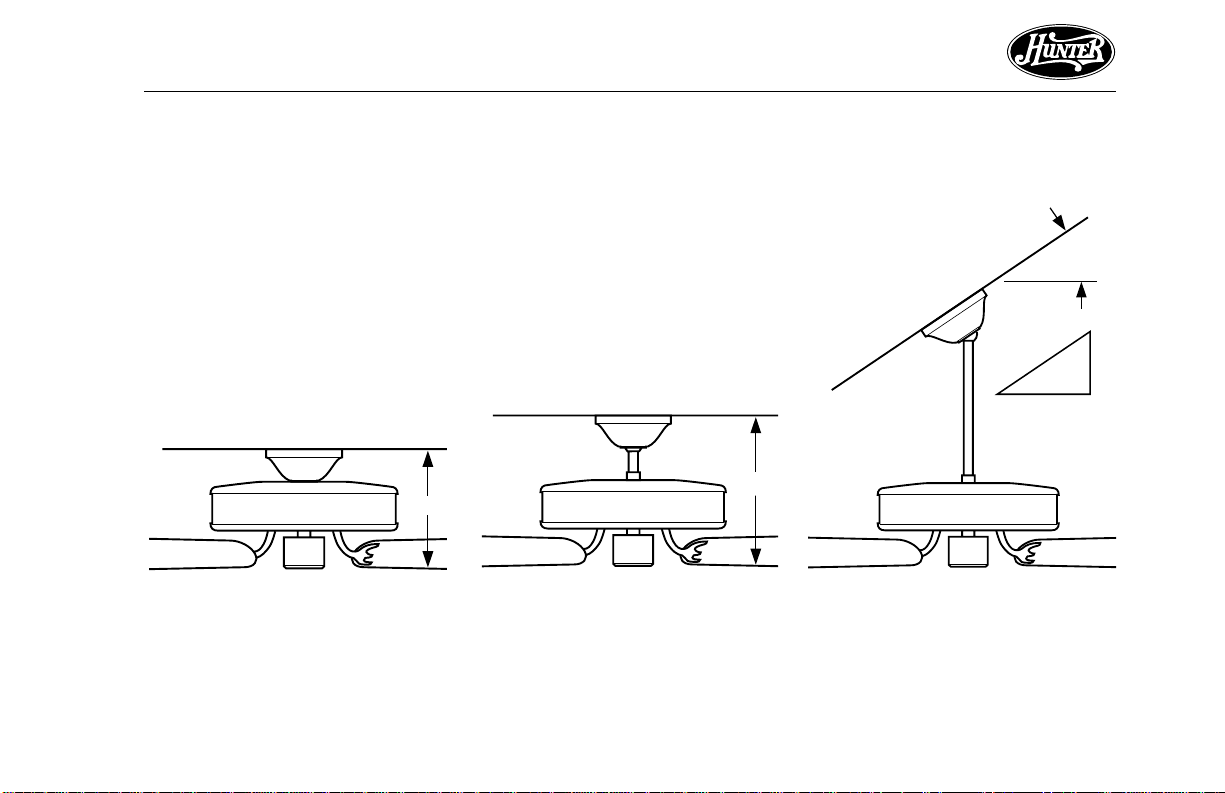
INSTALLER’S CHOICE®
This patented 3-position mounting
system provides you maximum installation flexibility and ease. You can
install your Hunter fan in one of three
ways. The steps in this manual include specific instructions for the fan
mounting method of your choice. For
a ceiling 8 feet or higher, standard
mounting is recommended.
10"
Figure 1a - Flush Mounting
Flush Mounting (Figure 1a) fits
close to the ceiling, for low ceilings
less than 8 feet high.
Standard Mounting (Figure 1b)
hangs from the ceiling by a connector pipe (included), for ceilings 8 feet
or higher. For ceilings higher than
eight feet, you can purchase Hunter
extension rods. All Hunter fans use
sturdy 3/4" diameter pipe to assure
stability and wobble-free performance.
12"
Figure 1b - Standard Mounting
Angle Mounting (Figure 1c) hangs
from a vaulted or angled ceiling.
Figure 1c - Angle Mounting
41457-01 7/2000
7
Page 8

®
STEP 2 - INSTALLING THE CEILING PLATE
1. Drill two pilot holes into the wood
support structure through the
outermost holes on the outlet
box. The pilot holes should be
9/64" in diameter by 2 3/4" in
depth.
2. Bring the lead wires around the
sides of the ceiling plate. Threading the lead wires through the
hole in the middle may cause
problems when installing the remote and trying to close the
canopy.
3. Your fan comes with two neoprene noise isolators. Position the
isolators between the ceiling plate
and ceiling by inserting the raised
areas on each isolator into the
holes in the ceiling plate. Refer to
Figure 2a.
4. Align the slotted holes in the ceiling plate with the pilot holes in
the wood support structure.
Note: The isolation pads should
be flush against the ceiling.
Isolators
Ceiling
Plate
Figure 2a - Adding Isolators to Ceiling
Plate
For Angle Mounting Only: Be
sure to orient the ceiling plate so
that the two hooks point up towards the ceiling peak as shown
in Figure 2b. Note: You will use
the hooks to support the fan
while wiring the fan.
Figure 2b - Correct Position of Ceiling
Plate for Angle Mounting
Ceiling Plate
Hooks
41457-01 7/2000
8
Page 9
5. Place a flat washer on each of the
two 3" screws and pass the
screws through the slotted holes
in the ceiling plate as shown in
Figure 2c.
6. Tighten the screws into the 9/64"
pilot holes; do not use lubricants
on the screws. Do not overtighten.
Ceiling Joist
2 x 4 Brace
®
Ceiling
Plate
Flat
Washer
Figure 2c - Attaching Ceiling Plate to
2 x 4 Brace
41457-01 7/2000
Ceiling
Outlet Box
3" Wood
Screw
9
Page 10
®
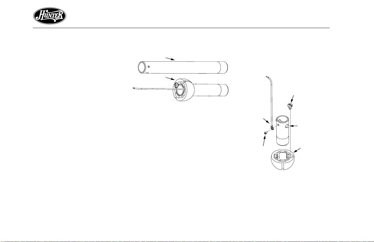
STEP 3 - ASSEMBLING PIPE/BALL ASSEMBLY
As discussed in STEP 1 - GETTING
READY, your Hunter fan can be installed in a standard mounting position.
Included with the fan are two pipes:
one 3" long pipe/ball assembly for
standard mounting on 8' ceilings a nd
one 12" long pipe for 9' ceilings and
higher. See Figure 3a.
If you are going to install the fan using the standard mounting, go to
STEP 4 - ASSEMBLING THE FAN.
If you are going to install the fan using the 12" long pipe for 9' ceilings
or higher , complete the steps below .
12" Pipe
3" Pipe/Ball
Assembly
Figure 3a - Pipes
REMOVING BALL ASSEMBLY
For the following steps refer to
Figures 3b and 3c.
1. Locate the 3" pipe/ball assembly.
2. Remove the positioning screw
from the top of the ball.
NOTE: The ball will become
loose and should slide down the
pipe.
3. Remove the ball from the pipe.
4. Remove the pin from the pipe.
Leadwire
Assembly
Ground
Screw
Figure 3b - Removing ball assembly
Positioning Screw
Pin
Ball
10
continued
41457-01 7/2000
Page 11
®
5. Carefully loosen and remove the
ground screw/leadwire assembly
from the pipe.
6. Locate the 12" pipe.
7. Insert and tighten the ground
screw/leadwire assembly into the
small screw hole on one end of
the 12" pipe.
CAUTION
Make sure that the leadwire
assembly is pointing straight
up and away from the pipe.
WARNING
• To avoid possible electrical
shock, the ground screw
must be tightened securely .
8. Insert the pin into the two holes
in the 12" pipe so that the pin is
placed evenly in the hole.
9. Insert the threaded end of the
pipe into the flat side of the ball.
10.Align the cutouts in the ball with
the pin and the ground screw assembly.
11.Slide the ball up the pipe until it
hits the pin.
12.Insert and tighten the positioning
screw into the ball so that the
head of the screw is tight on the
end of the pipe.
NOTE: Make sure that the ball
is positioned so that it is level or
straight.
Figure 3c - 12" pipe assembly
CAUTION
Do not overtighten the positioning screw as it may cause
the ball to seat improperly, resulting in fan wobble and the
fan hanging crookedly.
WARNING
• Failure to complete the
steps above properly could
result in the fan falling.
41457-01 7/2000
11
Page 12

®
STEP 4 - ASSEMBLING THE FAN
Use the Step 4 instructions for the
type of mounting you have selected:
standard, angle, or flush.
STANDARD AND ANGLE
MOUNTING
For Standard 8-foot Ceilings and
Higher
1. Insert the pipe through the
canopy as shown in Figure 4a.
Pipe
Canopy
Pipe
Setscrew
Figure 4a - Inserting Pipe through
Canopy
Feed wires from the fan through
the canopy then through the
pipe.
2. Screw pipe into fan assembly until tight. IMPORTANT! Tighten
pipe setscrew as shown in Figure
4a.
CAUTION
The pipe has a special coating
on the threads. Do not remove
this coating; the coating prevents the pipe from unscrewing. Once assembled, do not
remove the pipe.
FLUSH MOUNTING
For Low Ceilings
1. Tighten or r emove pipe setscrew .
Fit the canopy over the hanger
adapter as shown in Figure 4b.
Make sure the canopy fits snugly
against the fan assembly with no
space between the pieces.
2. You will find a large assembly
washer included with the fan.
Place the washer over the adapter
and canopy as shown in Figure
4b.
Assembly
Washer
Canopy
Adapter
Top of Fan
Figure 4b - Placing Canopy and
Washer Over Adapter
12
41457-01 7/2000
Page 13

®
3. Position the slots in the assembly washer over the threaded
holes in the adapter as shown
in Figure 4c.
Adapter
Assembly
Washer
Figure 4c - Positioning Assembly
Washer Slots over Threaded Holes
Threaded
Hole
4. Attach the canopy tightly to the
fan assembly with three #8-32
assembly screws and lockwashers
as shown in Figure 4d.
Assembly Screw
and Lockwasher
Figure 4d - Attaching Canopy to Fan
Assembly
41457-01 7/2000
13
Page 14

®
STEP 5 - HANGING THE FAN
1. Disconnect the power by turning
off the circuit breakers to the outlet box and associated wall switch
location.
2. T ilt and hang the assembled fan
from the ceiling plate hooks. Slip
two rectangular canopy slots over
ceiling plate hooks as shown in
Figures 5a and 5b.
Note: To hang the fan you must
tilt the canopy to an almost vertical position so the canopy slots
come down over the ceiling plate
hooks.
If you are installing the remote
continue to STEP 6, INSTALLING
THE REMOTE, otherwise skip to
STEP 7, WIRING THE FAN, on page
18.
Ceiling
Plate
Figure 5a - Attaching Slots on Canopy
to Ceiling Plate Hooks
14
Figure 5b - Assembled Fan Hanging
from Ceiling Plate Hooks
41457-01 7/2000
Page 15

STEP 6 - INSTALLING THE REMOTE
Remote Model #: UC7067RC
Ratings: 120 VAC, 60 Hz, 1.0 Amp Fan
250 Watts incandescent light
WARNINGS
• To avoid possible electrical
shock, before installing the
remote, be sure that all
power is disconnected by
turning off the circuit
breakers to the outlet box.
• All wiring must be performed in accordance with
national and local electrical
codes. If you are unfamiliar with the wiring codes,
you should use a qualified
electrician.
• To avoid overheating and
possible damage to other
equipment, do not install
to control a receptacle,
41457-01 7/2000
fluorescent light fixture,
motor operated appliance,
or transformer-supplied
appliance. Use only to control one paddle-blade ceiling fan and incandescent
light fixture.
Note: This device complies
with Part 15 of the FCC
Rules. Operation is subject
to the following two conditions: (1) this device may not
cause harmful interference,
and (2) this device must accept any interference received, including interference that may cause undesired operation.
®
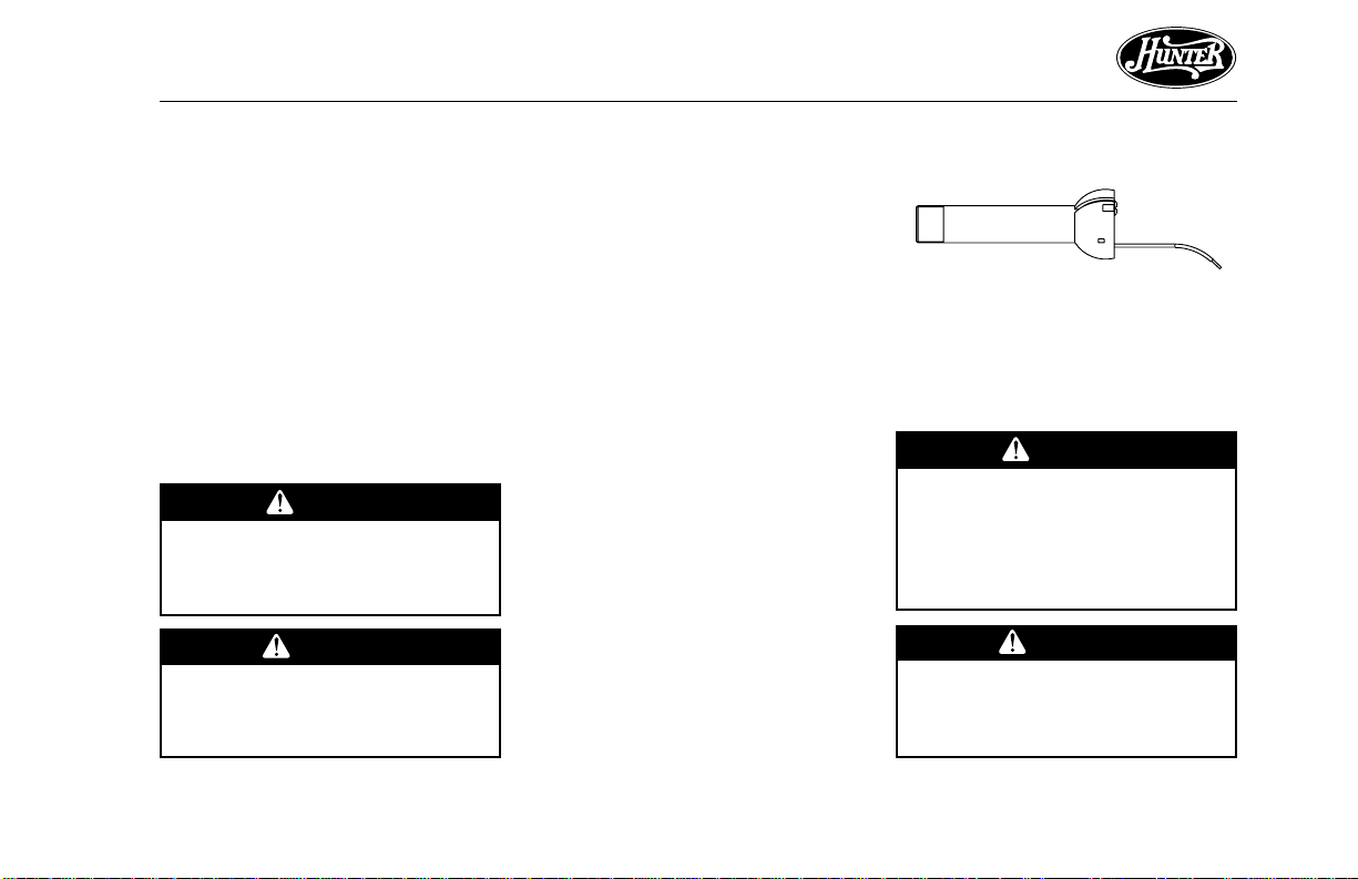
SETTING UP THE TRANSMITTER
1. Remove the battery cover from
the transmitter by pressing down
on the arrow and sliding the cover
off. Refer to Figure 6a.
Dip Switches
9 Volt Battery
Battery Cover
Figure 6a - Setting the Code on the
Transmitter
continued
15
Page 16

®
2. Slide the dip switches to the desired on/off position using a ballpoint pen or small-head screwdriver. Remember the on/off position of the switches for use
when setting up the receiver.
Note: Be sure to change the factory default switch settings to
your own unique code.
3. Install a 9 volt battery (not included). Refer to Figure 6a on
page 15.
Note: T o prevent damage to the
transmitter, remove the battery
if it is not used for long periods
of time.
4. Replace the battery cover on the
transmitter.
5. Mount the remote holder using
the two screws provided with the
remote kit. Slide out center piece
on the holder to see screw holes.
Replace center piece after mounting to wall. Refer to Figure 6b.
6. The transmitter can be placed on
the remote holder for convenience or safe-keeping.
Screw Hole
Cover
Screw Hole
Screw Hole
Figure 6b - Mounting the Remote
Holder
INSTALLING THE RECEIVER
1. Slide the dip switches to the same
on/off position as the transmitter
using a ball-point pen or smallhead screwdriver . Refer to Figur e
6c.
ON
ON
1234
Dip Switches
Figure 6c - Setting the Code on the
Receiver
16
41457-01 7/2000
Page 17

®
2. Make wiring connections using
the wire nuts supplied. To connect the wires, place bare metal
leads together. Place a wire nut
over the intertwined length of
wire and twist clockwise until
tight as shown. Refer to Figure
6d.
Antenna
Black/
White
Black/
White
3. Place receiver inside the canopy
under the ceiling plate. Refer to
Figure 6e. Be sure to keep the
antenna positioned securely on
top of the receiver . Do not modify
or damage the antenna wire, as
control performance may be reduced.
Black
White
White
Black
Black
White
AC
Power
In
Figure 6d - Wiring the Receiver
Connect .............................................................................................................. To
Green wire from fan.................................................................... B a re g round wire
Black wire from receiver .............................................................. Black supply wire
White wire from receiver ............................................................ White supply wire
White wire from receiver ......................................................... White wire from fan
Black wire from receiver ...........................................................Black wire from fan
Black/White wire from receiver.................................... Black/White wire from light
41457-01 7/2000
Note: For optimal performance,
the antenna should extend outside the canopy.
4. Continue to STEP 8, HANGING
THE FAN, on page 20.
Ceiling
Plate
Antenna
Receiver
Canopy
Figure 6e - Positioning the Receiver
Inside of the Canopy
WARNING
Once receiver is installed and
power is turned back on, DO
NOT pull the fan or light chains
while power is connected.
17
Page 18

®
STEP 7 - WIRING THE F AN
1. You can use either one or two
wall switches to control the fan
and/or lights separately . Use connection 1 on page 19 to
• control the light with a wall
switch and the fan with a
chain pull (one wall switch required)
• control the light with a chain
pull and the fan with a wall
switch (one wall switch required)
• control the light with one wall
switch and the fan with another (two wall switches required)
Use connection 2 on page 19 if
there is no separate wall switch
power wire for the light fixture.
Note: Wall switches not included.
18
2. Connect the wires as shown in
3. Separate the connected wires by
4. T urn the connectors upward. Push
Figure 7a. To connect the wires,
place the bare metal leads together. Place a wire nut over the
intertwined length of wire and
twist clockwise until tight as
shown.
placing the green and white wires
on one side of the outlet box and
the black and the black/white
wires on the other side of the
outlet box.
the wires gently into the outlet
box.
CAUTION
Be sure no bare wire or wire
strands are visible after making connections.
continued
41457-01 7/2000
Page 19

Wall Switch Wire For
Separate Control of Light Fixture
In
Black
White
Power
Wires
Ceiling
Bare or Green
2 x 4 Brace
(Note: Wall switch
must be acceptable
as a general-use
switch.)
Outlet Box
®
41457-01 7/2000
Green
Approved
Connectors
Green Ground
Wire from Hanger
Pipe (not present
with flush mounting
option)
Black
White
Ceiling
Plate
Connections:
Connect Blk/Wht Wire from fan
1
to Wall Switch Wire for separate
control of light fixture, or
Connect Blk/Wht Wire from fan
2
to Ceiling Black Wire if there
is no separate Wall Switch Wire
for the light fixture.
2
1
Black/White
3 Wires
From Fan
Figure 7a - Wiring The Fan
19
Page 20

®
STEP 8 - ATTACHING THE CANOPY
Sub-steps 1 and 2 apply to Flush,
Standard, and Angle mounting. Substep 3 applies to Standard and Angle
mounting only.
1. Swing the fan up so as to align
the canopy screw holes with the
mounting holes on the ceiling
plate. Refer to Figure 8a.
Ceiling
Plate
Canopy
2. Install and tighten the two #1032 x 1/2" mounting screws.
3. For Standard and Angle
Mounting Only: In addition to
sub-steps 1 and 2, lift the fan
housing towards the ceiling and
rotate the fan until each canopy
tab engages a groove in the
hanger ball as shown in Figure 8b.
Note: If the tabs are already engaged, do not rotate.
WARNING
Failure to complete sub-steps
1 through 3 could cause fan to
fall. (Sub-step 3 not applicable
for flush mounting.)
Groove in
Hanger Ball
Groove in
Hanger
Ball
Canopy
Tab
Figure 8b - Canopy Tabs and Grooves
in Hanger Ball
Figure 8a - Attaching Canopy to
Ceiling Plate
20
41457-01 7/2000
Page 21

STEP 9 - ASSEMBLING F AN BLADES
Hunter fans use several styles of fan
blade irons (brackets that hold the
blade to the fan).
1. Your fan may include blade grommets (see Parts List). If your fan
has grommets, insert them by
hand into the holes as shown in
Figure 9a.
2. Attach each blade to blade iron
using three blade assembly screws
as shown in Figure 9b. Some fans
Grommet
Fan
Blade
feature a decorative medallion as
well as a blade iron. Insert the
assembly screws into the blade
iron, through the blade and into
the medallion, with the blade
sandwiched between the blade
iron and medallion as shown in
Figure 9c.
®
If you used grommets, the blades
may appear slightly loose after
screws are tightened. This is normal.
3. Remove the blade mounting
screws and rubber shipping
bumpers from the motor.
Blade
Iron
Medallion
Figure 9a - Inserting Grommet into
Fan Blade
41457-01 7/2000
Figure 9b - Attaching Fan Blade to
Blade Iron
Figure 9c - Attaching Fan Blade to
Blade Iron using Decorative Medallion
21
Page 22

®
4. For each blade, insert one blade
mounting screw through the
blade iron as shown in Figure 9d,
and attach lightly to the fan. Insert the second blade mounting
screw , then securely tighten both
mounting screws.
Figure 9d - Attaching Blade Irons to
Hub of Fan Assembly
22
41457-01 7/2000
Page 23

STEP 10 - ATTACHING THE SWITCH HOUSING
The switch housing is made up of
two sections: the upper switch housing, and the lower switch housing.
ATTACHING THE UPPER SWITCH
HOUSING
1. Partially install two #6-32 x 3/8"
housing assembly screws into the
switch housing mounting plate as
shown in Figure 10a.
Switch
Housing
Mounting
Plate
Upper
Switch
Housing
Figure 10a - Attaching Upper Switch
Housing to Switch Housing Mounting
Plate
Housing
Assembly
Screw
Upper Plug
Connector
2. Feed the upper plug connector
through the center opening of the
upper switch housing. See Figure
10a.
3. Align the keyhole slots in the upper switch housing with the housing assembly screws installed in
sub-step 1.
4. Turn the upper switch housing
counterclockwise until the housing assembly screws are firmly
situated in the narrow end of the
keyhole slots as shown in Figure
10b. Install the one remaining #632 x 3/8" housing assembly screw
into the third hole in the upper
switch housing. Tighten all three
screws firmly.
CAUTION
Make sure the upper switch
housing is securely attached to
the switch housing mounting
plate. Failure to properly attach and tighten all three housing assembly screws could result in the switch housing and
light fixture falling.
Figure 10b - Mounting the Upper
Switch Housing
®
41457-01 7/2000
23
Page 24

®
ATTACHING THE LOWER
SWITCH HOUSING
Y our hunter fan includes one of two
lower switch housings. Both lower
switch housings are shown in Figures
10c and 10d. The type of lower
switch housing you have depends on
whether your fan includes a light fixture, and if so, what type of light fixture it is. Use table 10-1 to assist you.
If your fan has a lower switch housing as shown in Figure 10c, and you
ARE installing an accessory light kit
or single-globe light fixture included
with your fan, go directly to STEP
11 - INSTALLING LIGHT FIXTURE.
24
Figure 10c - Lower Switch Housing
Without Light Kit or Single-Globe
Light Fixture
Figure 10d - Lower Switch Housing
With Multi-Light Fixture
Table 10-1
Fan with no light
fixture included
Fan with accessory light kit included
Fan with multilight light fixture
included
See Figure 10c
See Figure 10c
See Figure 10d
continued
41457-01 7/2000
Page 25

®
If your fan has a lower switch housing as shown in Figure 10c and you
ARE NOT installing a light fixture, or
if your fan has a lower switch housing as shown in Figure 10d, complete the following steps:
1. Connect the upper plug connector from the motor to the lower
plug connector in the lower
switch housing assembly . See Figure 10e.
Note: Both plug connectors are
polarized and will only fit together
one way. Make sure that both
connectors are properly aligned
before connecting them together .
Incorrect connection could cause
improper operation and damage
to the product.
Upper
Switch
Housing
Lower Plug
Connector
Housing
Assembly
Screw
Figure 10e - Plug Connection and
Lower Switch Housing Installation
Upper Plug
Connector
Lower
Switch
Housing
2. Place the lower switch housing
assembly over the upper switch
housing. Align the side screw
holes in the upper and lower
switch housings. Attach the lower
switch housing to the upper
switch housing with three #6-32
x 3/8" housing assembly screws.
See Figure 10e.
Note: If your fan does not include
a light fixture, you may purchase
an accessory light kit separately.
See STEP 11 - INSTALLING LIGHT
FIXTURE.
41457-01 7/2000
25
Page 26

®
STEP 11 - INSTALLING LIGHT FIXTURE
Your fan may include a light fixture.
Information for wiring and installing
all included Hunter light fixtures follows.
Note: If you purchased a fan without a light fixture, you may purchase
an accessory light kit separately. For
best performance and beauty, use
only Hunter-brand light kits, Type AZ. Hunter light kits are designed,
tested, and UL approved for all
Hunter fans, and are available at
most Hunter dealers. To install the
light kit, follow the instructions included with the kit.
If you are not installing a light fixture, turn to OPERATING YOUR
HUNTER FAN for additional instructions.
26
• To avoid possible electrical
shock, before installing
light fixtures, disconnect
power by turning off the
circuit breakers both to the
outlet box and to its associated wall switch location.
If you cannot lock the circuit breakers in the off position, securely fasten a
prominent warning device,
such as a tag, to the service
panel.
• Connect house wiring to
the fan before attaching
the light fixture to the fan.
• All wiring must be in accordance with national and local electrical codes and
ANSI/NFPA 70. If you are
unfamiliar with wiring, you
should use a qualified electrician.
WARNING
INSTALLING INCLUDED ACCESSORY LIGHT KIT
1. Remove the plug and switch
housing caps from the lower
switch housing. Refer to Figure
11a.
Note: Do not discard the caps.
You will need this if you remove
the light fixture in the future.
2. Locate the white wire and the
black wire coming from the light
fixture.
3. Thread the two wires from the
light fixture through the center
hole in the lower switch housing.
Be sure to thread the black wire
with the larger connector head
through first and then thread the
white wire with the smaller connector head through.
41457-01 7/2000
Page 27

®
Lower
Switch
Housing
Switch
Housing
Cap
Plug Button
Figure 11a - Removing Plug Button
and Switch Housing Cap
4. Screw the fixture into the lower
switch housing. Thread the
lockwasher and nut provided over
41457-01 7/2000
the wires. Making sure the light
fixture mounting screw holes are
aligned; hold the light fixture and
tighten the nut on the inside of
the lower switch housing. Insert
and tighten the two #6-32 sems
light fixture mounting screws.
5. Refer to Figure 11b. Locate the
black/white wire and the white
wire in the fan switch housing
that have connectors attached.
Pull the dummy terminals out of
both connectors. Connect the
black/white wire to the black wire
of the light kit. Connect the white
Wires From
The Fan
Figure 11b - Wiring Connections for Light Kit
CAUTION
Be sure no bare wire or wire
strands are visible after making connections.
wire to the white wire of the light
kit.
6. Connect the upper plug connector from the motor to the lower
plug connector in the lower
switch housing assembly . See Figure 10e on page 25.
Dummy Terminals
(to be removed when
hooking up light kit)
Wires From
The Light Kit
continued
27
Page 28

®
Note: Both plug connectors are
polarized and will only fit together
one way. Make sure that both
connectors are properly aligned
before connecting them together .
Incorrect connection could cause
improper operation and damage
to the product.
7. Place the lower switch housing
assembly over the upper switch
housing. Align the side screw
holes in the upper and lower
switch housings. Attach the lower
switch housing to the upper
switch housing with three #6-32
x 3/8" housing assembly screws.
See Figure 10e on page 25.
Figure 11c - Installing the Globes
INSTALLING INCLUDED ACCESSORY LIGHT FIXTURE GLOBES
AND BULBS
1. Place globe over threaded
lampholder in cup. Install and
hand tighten threaded locking
ring on lampholder as shown in
Figures 11c and 11d.
2. Install bulbs. Use 120V, 60W
maximum medium base incandescent bulbs. T urn power ON at
main panel.
Cup
Threaded
Lamp Holder
Threaded
Globe
Locking Ring
Note: As shown in Figure 11d,
line up the beginning of the first
thread on the lampholder and
notch on the locking ring to
avoid cross threading the ring.
If the ring becomes hard to turn,
rotate the ring counter clockwise
to loosen and reposition. Do not
force the ring on.
Beginning of
First Thread
Threaded
Locking Ring
Notch in Ring
Figure 11d - Assembling the Locking
Ring
28
41457-01 7/2000
Page 29

®
INSTALLING SINGLE-GLOBE
FIXTURE BULB AND GLOBE
Refer to Figure 11e.
1. Install light bulbs.
2. Insert the globe around the bulb
and into the fixture. Install and
tighten thumbscrews manually.
Do not overtighten.
Thumbscrew
Globe
Bulb
Figure 11e - Single-Globe Fixture
INSTALLING INTEGRATED MULTILIGHT FIXTURE BULBS AND
GLOBES
Refer to Figure 11f.
1. Place silencer band around the
neck of each globe.
2. Insert globe in cup.
3. Install and tighten thumbscrews
manually. Do not overtighten.
4. Install bulbs.
Thumbscrew
Cup
Globe
Figure 11f - Multi-Light Fixture
Silencer
Band
INSTALLING ACCESSORY LIGHT
KITS
To install the light kit, follow the instructions included with the kit for
wiring, mounting, and assembly . After completing the light kit installation, follow sub-steps 1 and 2 on
page 23 to reattach the lower switch
housing.
41457-01 7/2000
29
Page 30

®
OPERATING YOUR HUNTER FAN AND REMOTE
Your Hunter Fan comes with an
acessory pull chain pendant for both
fan and light operation. T o install the
pull chain pendants, insert the loose
end of the pull chain pendant into
the breakaway connector on the fan
and light pull chains.
OPERATING YOUR HUNTER FAN
WITHOUT REMOTE
1. Turn on electrical power to the
fan.
2. The pull chain controls power to
the fan. The chain has four settings in sequence: High, Medium,
Low and Off.
• Pull the chain slowly to change
settings.
• Release slowly to prevent the
chain from recoiling into the
blades.
• The chain uses a breakaway
connector that separates if the
chain is jerked. If this happens,
simply reinsert the chain into
the connector.
3. Ceiling fans work best by blowing air downward (counterclockwise blade rotation) in warm
weather to cool the room with a
Figure 12a - Air Flow Patterns
direct breeze. In winter, having
the fan draw air upward (clockwise blade rotation) will distribute the warmer air trapped at the
ceiling around the room without
causing a draft. Refer to Figure
12a.
To change the direction of air
flow, turn the fan off and let it
come to a complete stop. Slide
the reversing switch on the fan
to the opposite position as shown
in Figure 12b. Restart fan.
4. If your fan wobbles when operating, use the enclosed balancing
kit and instructions to balance the
fan.
Pull
Chain
Figure 12b - Pull Chain and Reversing
Switch
Reversing
Switch
30
41457-01 7/2000
Page 31

®
OPERATING YOUR HUNTER FAN
WITH A REMOTE
WARNING
Once receiver is installed and
power is turned back on, DO
NOT pull the fan or light chains
while power is connected.
Refer to steps 1, 3, and 4 in the OP-
ERATING YOUR HUNTER FAN
WITHOUT A REMOTE. Use the
following steps to operate your
remote.
1. Turn ON the wall switch. The light
will turn ON at maximum brightness.
2. Light Operation:
Press and quickly release the light
button on the hand held remote
to turn the light OFF or ON.
Press and hold the light button for
more than 0.7 second to dim or
brighten the light. Release the
light button when the desired
light level is reached. The light
dimmer range is 20% to 100%.
The Light key has auto resume,
so the brightness will stay the
same as the last time it was turned
OFF. Refer to Figure 12c.
3. Fan Operation:
Press the fan button to turn ON
the ceiling fan at High speed.
Press again to change the speed
to Medium, then again to Low,
and then again to turn the fan
OFF. Refer to Figure 12c.
Note: If fan is not reaching desired speed or light does not
come on, refer to the TROUBLESHOOTING section.
Display
LOW MED HIGH
Light Button
Fan Button
Figure 12c - Remote Transmitter
41457-01 7/2000
31
Page 32

®
CLEANING AND MAINTENANCE
Caring for finishes: For cleaning, a
soft brush or lint-free cloth should
be used to prevent scratching the finish. A vaccuum cleaner brush nozzle
can remove heavier dust. Surface
smudges or an accumulation of dirt
and dust can easily be removed by
using a mild detergent and a slightly
dampened cloth. An artistic agent
may be used, but never use abrasive
cleaning agents as they will damage
the finish.
Caring for blades: Wood finish
blades should be cleaned with a furniture polishing cloth. Occasionally,
a light coat of furniture polish may
be applied for added protection and
beauty. Painted and high-gloss
blades may be cleaned in the same
manner as the fan finish.
MANUFACTURER'S
PHONE NUMBER
If you need parts or service
asssitance, please call 901-248-2222
or visit us at our WEB site at:
http://www.hunterfan.com
32
41457-01 7/2000
Page 33

TROUBLESHOOTING
PROBLEM PROBABLE CAUSE SOLUTION
Nothing happens; fan does not move.
Without Remote (refer to page 35 for
troubleshooting With Remote).
1. Power turned off, fuse blown, or
circuit breaker tripped.
2. Loose wire connections or wrong
connections.
3. Motor reversing switch not engaged.
4. Pull chain switch not “on.”
5. Shipping bumpers still in place.
1. T urn power on, replace fuse, or r eset breaker.
2a.Loosen canopy, check all connections
according to STEP 7 - WIRING THE
FAN (turn power off before
checking).
2b.Check the plug connection in the
switch housing according to STEP
10 - ATTACHING THE SWITCH
HOUSING.
3. Push switch firmly up or down.
4. Pull switch chain.
5. Remove shipping bumpers.
®
Noisy operation.
41457-01 7/2000
1. Blade brackets screwed loosely to
motor.
2. Blade screwed loosely to blade iron.
3. Blade cracked.
1. Tighten screws until snug.
2. Tighten screws until snug.
3. Replace all blades.
continued
33
Page 34

®
PROBLEM PROBABLE CAUSE SOLUTION
Noisy operation (continued).
4. Using non-approved speed control.
5. Glass screwed loosely to fixture.
4. Change to approved speed control.
5. Hand-tighten the light fixture
screws. Ensure that rubber noise
isolators are installed.
6. Switch housing is loose.
6. Check and tighten screws to the
switch housing mounting plate and
to the upper and lower switch
housing.
Excessive wobbling.
Note: When switching from medium
to low speed, you may notice some fan
wobble. When the fan stabilizes at low
speed, wobble will disappear.
1. Unbalanced blades.
2. Loose blades or blade irons.
3. Fan not secure on hanger assembly.
4. Fan hanger ball not seated in
canopy tabs.
1. Use balancing kit included with fan.
2. Tighten all screws.
3. Turn power off, support fan very
carefully, loosen canopy and hang
correctly.
4. Turn power off, support the fan
very carefully, and check that the
hanger ball is properly seated.
If you have tried these troubleshooting solutions and still have trouble, call 901-248-2222 or visit our
Web site at http://www.hunterfan.com.
34
continued
41457-01 7/2000
Page 35

PROBLEM PROBABLE CAUSE SOLUTION
No functions operate or do not operate
correctly. (With Remote)
1. Main Power not restored.
2. Fan pull chain not set to High.
1. Replace fuse. Turn ON circuit
breaker. Turn ON wall switch.
2. Turn OFF power at wall switch
or main electric panel. Set fan
to High speed.
3. Light pull chain not set to ON.
4. Receiver wiring incorrect.
5. Transmitter and receiver dip
switches do not match.
6. Battery too weak.
3. Set light kit to ON.
4. Verify wiring connections.
5. Set transmitter and receiver to
same dip switch setting.
6. Replace with new battery.
®
Operates only at close range. (With Remote)
Inconsistent operation. (With Remote)
41457-01 7/2000
1. Signal blocked from reaching
receiver.
2. Battery too weak.
1. Signal partially blocked from
reaching receiver.
2. RF interference.
3. Continuing RF interference.
1. Extend antenna into ceiling box,
or move it for better reception.
2. Replace with new battery.
1. Extend antenna into ceiling box,
or move it for better reception.
2. Turn OFF wall switch for 5
seconds, then turn back ON.
3. Change dip switch settings to a
different code in both Transmitter and Receiver.
35
 Loading...