

Page 1
INSTALLATION INSTRUCTIONS FOR
HUNTER CEILING FAN LIGHT KIT
READ AND SAVE THESE INSTRUCTIONS
CAUTION:
1. Read entire instructions carefully before beginning installation.
2. To avoid possible shock, be certain electricity is shut OFF at
main panel before wiring.
3. All wiring must be in accordance with national and local electrical code.
4. Professional installation recommended.
Pre Installation Preparation
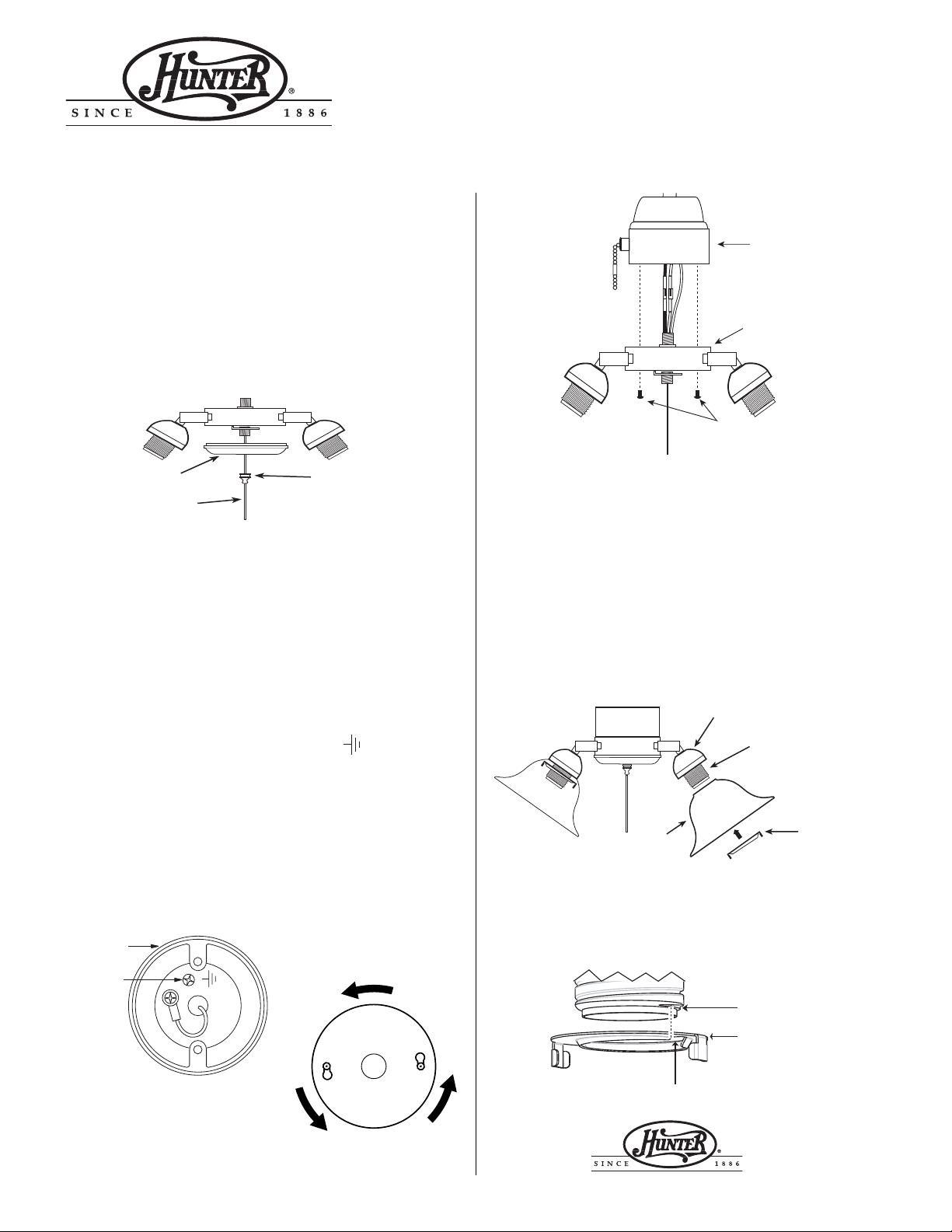
Unscrew the decorative finial on the light kit by turning it counter
clockwise. Slide it off over the pull cord, removing the keeper on
the end of the cord only if necessary. Remove the light kit cover
plate. See Figure 1.
FLUSH MOUNT STYLE
Fan Switch Housing
FIGURE 4
Light Kit
FIGURE 1
Light Kit Cover Plate
Pull Cord
Remove the cover plate from the fan switch housing.
Note: Do not discard the switch housing cover plate. You will
need to replace it if you remove the light fixture in the future.
Decorative Finial
Wire the Light Kit
CAUTION: This appliance must be earthed.
Locate the two wires in the fan switch housing that have connectors
attached. Pull the plugs out of both connectors. Connect the black
and white wire to the brown wire of the light kit. Connect the blue
wire to the blue wire of the light kit. Be sure to connect the green
and yellow ground wire to the screw marked
base of the switch housing. See Figure 2.
located at the
Complete the Assembly
Attach the light kit to the fan switch housing using the screws
provided, leaving screws slightly loose temporarily. Make sure all
wires fit flush inside the switch housing. See Figures 3 and 4 .
Rotate the light kit counter clockwise as seen from below, until it
stops, so the screws are lined up in the narrow notches in the mounting holes. See Figure 3 Tighten the screws securely.
FAN SWITCH
HOUSING
GROUND
SCREW
FIGURE 2
Screws
Feed the pull cord back through the light kit cover and the decorative finial. Center the light kit cover on the threaded nipple, making sure no wires are caught or in the way. Thread the decorative
finial onto the threaded nipple and hand tighten. Re-install the
cord keeper if it was removed previously.
Installing Globes and Bulbs
Place globe over threaded lampholder in cup. Install and hand
tighten threaded locking ring on lampholder as shown in figures 5
and 6
Install bulbs. Use E-27 bulb, no smaller than A-19 (60mm diameter). Turn power ON at main panel.
FIGURE 5
Globe
Note: As shown in Figure 6, line up the beginning of the first
thread on the lamp holder and notch on the locking ring to
avoid cross threading the ring. If ring becomes hard to turn,
rotate ring counter clockwise to loosen and reposition. Do
not force the ring on.
FIGURE 6
Notch in Ring
Cup
Threaded
Lamp
Holder
Threaded
Locking Ring
Beginning of
First Thread
Threaded
Locking Ring
FIGURE 3
41449-01 05/00 ©2000 HUNTER FAN CO
HUNTER FAN COMPANY
2500 FRISCO AVENUE
MEMPHIS, TN 38114
 Loading...