

Page 1
40955-01 1/91 ©1991 HUNTER FAN CO.™
-1-
SINCE 1 8 8 6
CAUTION:
1. Read entire instructions carefully before beginning
installation.
2. To avoid possible electrical shock, be certain electricity is
shut off at main panel before wiring.
3. All wiring must be in accordance with national and local
electrical codes. If you are unfamiliar with wiring, you
should use a qualified electrician.
WARNING:
1. To reduce the risk of fire or electrical shock, do not use a
solid state speed control with this fan. Use Hunter Control
Model 22691.
2. To reduce the risk of personal injury, do not bend the blade
brackets when installing the brackets, balancing the blades
or cleaning the fan. Do not insert foreign objects in between
rotating fan blades.
Step 1: Pre-Installation Instructions
A. Select installation site. Check to make sure that in normal
use no object can come in contact with the rotating fan blades.
The mounting site should also meet the precautions listed in
Step 3 below.
B. Installation hardware is included for a standard drywall or
plaster ceiling. You will need a 4" x 1
1
⁄
2
" or 4" x
1
⁄
2
" outlet box
and wire nuts (2) which can be purchased from any hardware
store or electrical supply house.
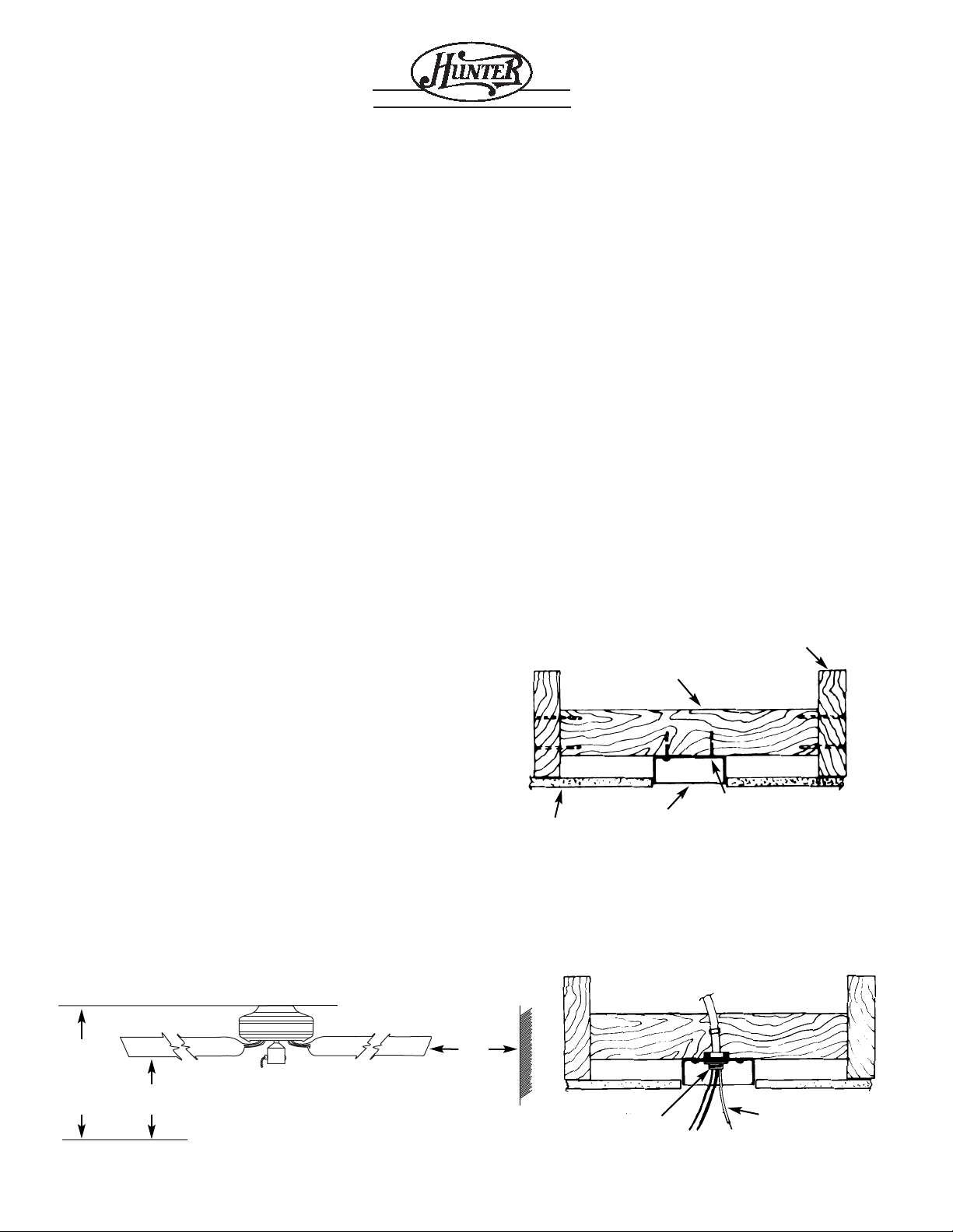
C. The fan blades must be mounted at least 7' above the floor.
For maximum efficiency, they should not have any obstruction
(walls, posts, etc.) within 24" of the blade tips. See Figure 1 for
mounting distances.
Step 2: Inspection of Fan
A. Unpack unit carefully to avoid any damage to the compo-
nents.
B. Check for any shipping damage to the motor and the fan
blades. If more than one fan is being installed, keep the matched
and balanced fan blades in sets, as they were shipped. Should
one of the fan blades become damaged during shipment, return
all blades in the set for replacement.
C.Check contents to be certain it contains a bag of parts.
Step 3: Installation of Outlet Box
and Rough-In Wiring
CAUTION: Your Hunter ceiling fan with accessories can weigh
up to 35 lbs. The following precautions must be taken for safety
and to ensure that your fan is securely mounted to the ceiling.
• Be certain electricity is “OFF” at the fuse panel when
inspecting or repairing installation site.
• All wiring must meet local and national electrical codes.
• Do not mount directly to an unsupported ceiling or to an electrical outlet box. Mounting must support a 35 lb. fan with
accessories.
A. Secure a metallic outlet box 4" x 1
1
⁄
2
" or 4" x
1
⁄
2
" deep to
2 x 4 cross brace between two ceiling joists as shown in
Figure 2. The outlet box must be recessed in the ceiling by
1
⁄
16
"
minimum. Secure the outlet box to the cross brace by drilling
(2) pilot holes no larger than the minor diameter of the woodscrews (
5
⁄
64
") and use two #8 x 1
1
⁄
2
" woodscrews and washers.
Use the innermost holes for securing the box. Orient the box so
the outermost holes are aligned with the 2 x 4 brace. The outermost holes will be used in Step 4B.
CAUTION: Do not use a lubricant on screws.
B. Bring electrical cable into the outlet box and attach with an
approved connector. Make certain that wiring meets all national
and local electrical codes. Wire leads should extend at least 6"
beyond outlet box for ease in making connections. See Figure 3.
INSTALLATION INSTRUCTIONS
FOR HUNTER CEILING FANS USING INSTALLER’S CHOICE MOUNTING
READ AND SAVE THESE INSTRUCTIONS
2 X 4 WOOD BRACE
OUTLET BOX
CEILING
CEILING JOIST
FIGURE 2
#8 WOODSCREW
& WASHER (2) REQUIRED
CONNECTOR
FIGURE 3
6" MIN. LEAD LENGTH
24"
8' MIN.
CEILING
TO
FLOOR
7' MIN.
TO FLOOR
FIGURE 1
CLEARANCE
TO OBSTRUCTIONS
¤
Page 2
40955-01 1/91 ©1991 HUNTER FAN CO.™
-2-
Step 4: Installation of Ceiling Plate
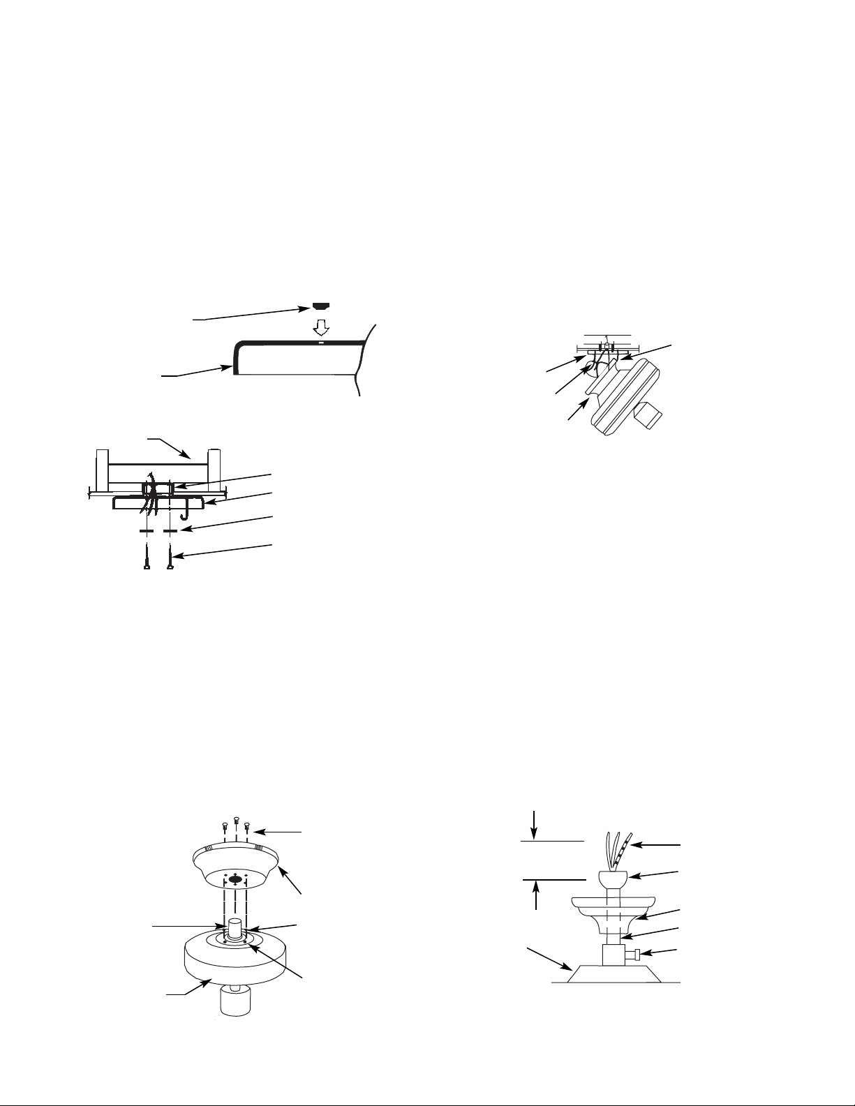
A. Install the (3) rubber bushings into the top of the ceiling
plate by inserting small side of the bushing into the three holes
in the ceiling plate. See Figure 4A.
B. Thread the lead wires through the opening in the ceiling
plate and install the ceiling plate to the 2 x 4 brace which supports the outlet box. Use (2) #10 woodscrews 3" long and (2)
flatwashers for mounting. Drill (2) pilot holes for the mounting
screws
9
⁄
64
" diameter. See Figure 4B.
NOTE: When attaching ceiling plate to the outlet box support,
make certain bushings remain in place.
NOTE: Tighten the ceiling plate mounting screws only enough
to provide slight compression of the bushings. Do not overtighten.
NOTE: Assembly Methods for
Installer’s Choice Hanging System
Your new Hunter fan can be hung in (2) different manners, one
being as a low profile fan and also as a ball type hanging fan.
Thus, installer’s choice. Customer should read Steps 5 through
7 and decide which style of mounting to use.
Step 5: Fan Assembly Low Profile Fan
A. The canopy has (4) holes in the bottom. The large center
hole fits over the adaptor on top of the fan. The (3) remaining
holes are for the canopy assembly screws.
Place the canopy on top of the fan and align the proper holes.
See Figure 5. Make certain you have located the hole pattern by
checking to see that the canopy sits flat on top of the fan without a space between the bottom of the canopy and the top of the
fan. If a space is present, rotate the canopy slightly, eliminating
the space.
B. Next, secure the canopy to the top of the fan using (3) #10-
32 screws with lockwashers packaged with the adaptor kit.
Make certain the screws are tight. Failure to do so could result
in the fan falling.
CAUTION: To ensure proper engagement of the canopy assembly screws, the canopy must fit snug against the top of the fan.
CAUTION: Do not lift motor by wires.
C. Being careful not to scratch the canopy finish, hang the fan
from the hook in the ceiling plate using one of the (2) slots in
the canopy. See Figure 5A.
Hanging Fan
CAUTION: Do not lift motor by wires.
A. Insert pipe nipple through canopy and feed wires from top
of motor through pipe nipple. Screw pipe nipple into fan until
tight (at least 4
1
⁄
2
turns). The setscrew locking the pipe nipple to
motor must be tightened very securely. See Figure 5B. Failure
to tighten screw could result in fan falling.
CAUTION: The pipe nipple has a special coating on the
threads. Do not remove. The coating is to help prevent the nipple from unscrewing.
B. Being careful not to scratch the canopy finish, hang the fan
from the hook in the ceiling plate using one of the (2) slots in
the canopy. See Figure 5A.
NOTE: For mounting fan on vaulted ceiling, there are (2) sets
of holes on the side. Locking tab in side must be in up position.
Use set of holes in ceiling plate that assures locking tab in
canopy is in the up position.
FIGURE 4A
BUSHING
CEILING PLATE
OUTLET BOX
CEILING PLATE
FLAT WASHER
MOUNTING SCREWS
FIGURE 4B
2 x 4 BRACE
FIGURE 5
SCREWS WITH
LOCKWASHERS
AND LOCTITE ON
THREADS
CANOPY
SCREW HEAD
SCREW HOLE
ADAPTOR
FAN ASSEMBLY
CEILING PLATE
HOOK
CEILING PLATE
GROUND WIRE
CANOPY
FIGURE 5A
FIGURE 5B
6” MIN
MOTOR
LEAD WIRES
PIPE NIPPLE BALL
CANOPY
PIPE NIPPLE
SETSCREW
(TIGHTEN
SECURELY)
PIPE NIPPLE
Page 3
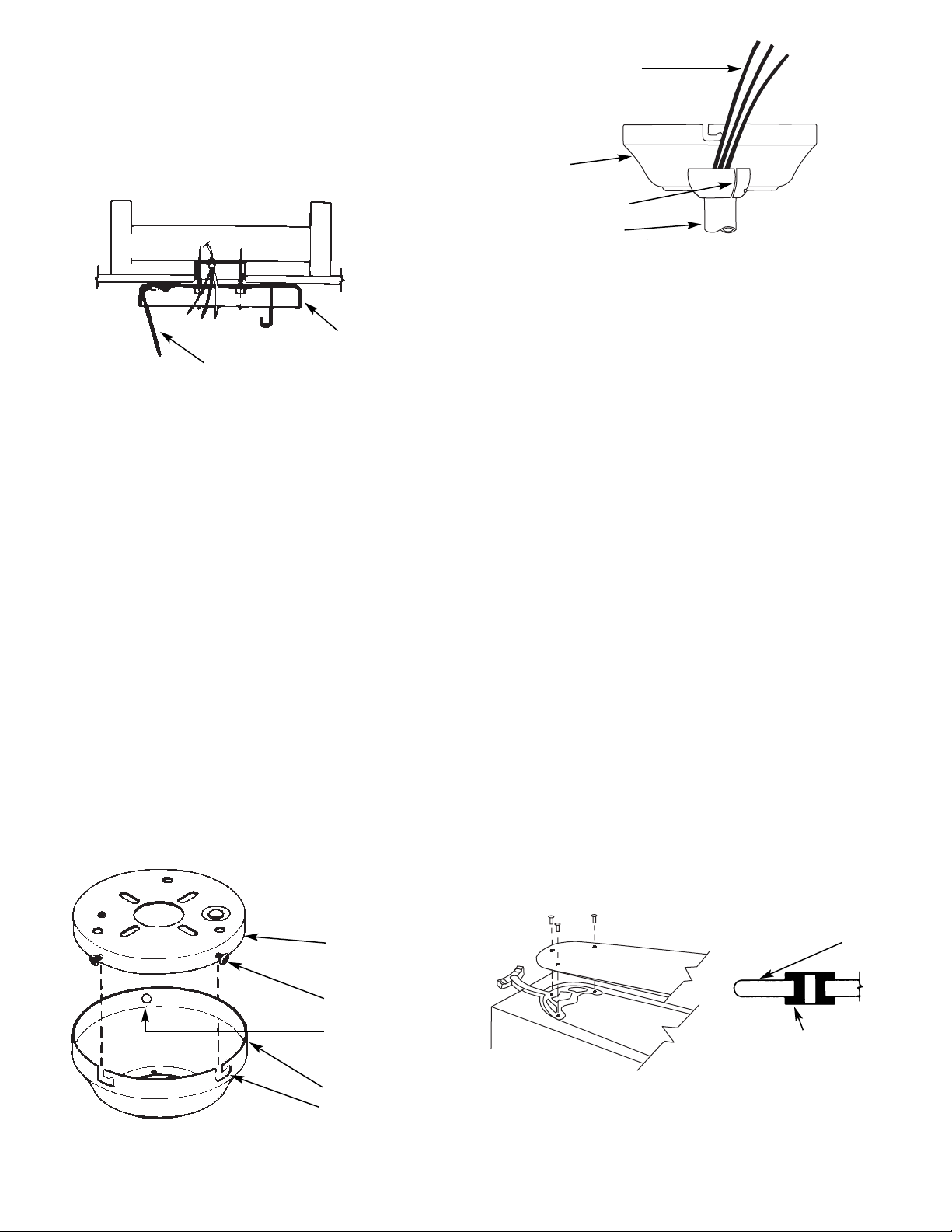
Step 6: Final Wiring
A. Connect electrical supply leads to the leads from motor,
using approved connectors. Connect black electrical supply lead
to the black motor lead and the black with white stripe motor
lead (see Note). Connect the white electrical supply lead to the
white motor lead. Connect the ground wire to the green leads
from the motor and ceiling plate. See Figure 6.
NOTE: If a separate wall switch will be used to control a lighting accessory, connect the black wire with white stripe to the
wall switch lead. The wall switch must be acceptable for use as
a general-use switch.
CAUTION: No bare wire or wire strands should be visible
after making connections.
B. After making the wire connections, the wires should be
spread apart with the white and green wires on one side of the
outlet box, and the black and black/white wires on the other side
of the box.
The splices should be turned upward and pushed carefully up
into the outlet box.
Step 7: Finish Fan Assembly
A. The ceiling plate has (3) mounting screw holes located on
the side. Install (2) #10-32 x
1
⁄
2
" Phillips round head screws
halfway into two of these holes. See Figure 7.
Remove the fan from the ceiling plate hook. Make sure not to
break any wire connections. The canopy has (2) mating slots
and (1) mating hole. See Figure 7.
B. Position (2) slots in canopy directly under and in line with
(2) mounting screws in ceiling plate. Lift fan until ceiling plate
mounting screws are seated in bottom of slots in canopy. Rotate
fan counterclockwise until both mounting screws drop into slot
recesses. Tighten screws securely. Install third screw into
mounting hole.
CAUTION: Failure to securely assembly the canopy screws
could result in the fan falling.
NOTE: For the handing fan configuration, rotate fan until
groove in ball is positioned over tab in canopy. Make certain
groove and tab are engaged before running fan. See Figure 7A.
Failure to do this could result in the fan falling.
Step 8: Fan Blade Assembly,
Installation, and Balancing
A. Attach wood blades to blade brackets using three screws for
each blade. See Figure 8. If your blades have large holes you must
first insert the rubber grommets into the holes. See Figure 8A.
NOTE: Grommets are usually assembled by hand. If you use a
tool, make certain you do not damage the grommet or blade
when inserting the grommets.
Next assemble the blade to the blade bracket. Make sure all
screws are tight to prevent vibration or wobbling. A cavity in
the styrofoam packaging has been provided to nest the parts in
during assembly to assure correct alignment of parts.
Even when the screws are tight, the blades may seem to be
loose. This is normal when using grommets and will not be
a problem.
GREEN GROUND WIRE
CEILING PLATE
FIGURE 6
CEILING PLATE
MOUNTING SCREWS
MOUNTING HOLE
CANOPY
MOUNTING SLOTS (2)
FIGURA 7
40955-01 1/91 ©1991 HUNTER FAN CO.™
-3-
FIGURA 7A
LEAD WIRES
ROTATE BALL UNTIL GROOVE IN BALL
ENGAGES TAB IN CANOPY
CANOPY
GROOVE IN BALL
PIPE NIPPLE
BLADE
GROMMET
FIGURE 8 FIGURE 8A
Page 4

FIGURE 11
PULL CHAIN
SWITCH
BLADE MOUNTING
SCREWS
NOTE: MAKE
CERTAIN ALL
SCREWS ARE
TIGHT.
BREAKAWAY
CONNECTOR
REVERSING
SWITCH
PURCHASED ACCESSORY
CHAIN (IF DESIRED)
B. Remove the screws and rubber bumpers from the motor
hub. Insert a mounting screw (provided) in hole in blade bracket. Use a screwdriver to hold in place. Align blade holes with
mounting holes in hub by turning screw and readjusting blade
bracket until screw mates with threaded hole in hub. Do not
tighten until both screws have been put in blade bracket. Repeat
for all blades. See Figure 10.
C. A blade balancing kit has been provided with your fan.
Should the fan wobble in operation, you may use this kit to correct the balance per the instructions supplied with the kit.
Step 9: Light Kit Installation
A. Install the light kit in accordance with the instructions sup-
plied with it.
NOTE: Some Hunter fans require a special adaptor plate
between the switch housing and the light kit. This plate is provided with those fans which need it. It should be installed as
shown in Figure 10. If the switch housing on your fan is 3
1
⁄
4
"
diameter or less you do not need the adaptor, mount the light kit
directly to the switch housing.
Step 10: Operation of Fan
A.Turn electrical service on at main panel.
B. Switch operates in this sequence: “High,” “Medium,”
“Low,” “OFF.” Pull chain slowly to operate. Also, release the
chain slowly so as to prevent chain from flying up into blades,
possibly resulting in damage to blades, or pull chain. The breakaway connector is designed to separate from the chain at a predetermined force. If this separation occurs, simply reinsert the
connector. It can be reused again and again. See Figure 11.
C. Motor is electrically reversible. When first operating fan,
determine direction of air flow. If you wish to change direction,
switch fan off and allow to stop. Slide reversing switch to the
opposite position and switch fan back on. See Figure 11.
Speed Control
As an option, a wall mounted speed control switch is available
from your Hunter dealer.
FIGURE 10
LIGHT KIT
ADAPTOR
LIGHT KIT
40955-01 1/91 ©1991 HUNTER FAN CO.™
-4-
Page 5

40955-01 1/91 ©1991 HUNTER FAN CO.™
-5-
TROUBLESHOOTING GUIDE
PROBLEM PROBABLE CAUSE SOLUTION
1. Nothing happens;
fan does not
move.*
2. Noisy operation.
3. Excessive
wobbling.
1. Power turned off or fuse blown.
2. Loose wire connections or wrong connections.
3. Motor reversing switch not engaged.
4. Pull chain switch not “on”.
5. Rubber shipping blocks not removed.
1. Blade brackets loosely screwed to motor.
2. Blade screwed loosely to blade bracket.
3. Blade cracked.
4. Non-approved speed control being used.
1. Blade brackets not attached at proper locations.
2. Unbalanced blades.
3. Fan too close to vaulted ceiling.
4. Loose blades or blade brackets.
5. Fan not secure on hanger assembly.
1. Turn power on or replace fuse.
2. Loosen canopy. Check all connections.
(Turn power off while checking.)
3. Push switch firmly to one side or the other.
4. Pull switch chain.
5. Remove shipping blocks.
1. Tighten screws until snug.
2. Tighten screws.
3. Replace all blades.
4. Change to approved speed control.
1. Carefully review Step 8.
2. Use balancing kit. (See Step 8E.)
3. Lower or move fan.
4. Tighten all screws.
5. Turn power off, support fan very carefully,
loosen canopy and hang correctly.
*NOTE: If blades will not turn by hand, contact your nearest service representative.
When switching from medium to low speed, you may notice some fan wobble. When fan speed stabilizes at low speed, wobble will disappear. If you have checked the above problems and still have trouble, call (901) 248-2222.
NOTE: This ceiling fan may have four or five blades. If you have trouble attaching the blade brackets to the motor, carefully review Step 8.
Page 6

HUNTER FAN COMPANY
2500 FRISCO AVENUE
MEMPHIS, TN 38114
®
©1991 HUNTER FAN CO.™
 Loading...