

Page 1

INSTALLATION INSTRUCTIONS FOR HUNTER
DUAL MOUNT LIGHT FIXTURES
MODEL 28393, 28394
IMPORTANT NOTE: READ AND SAVE THESE INSTRUCTIONS!
NOTE: This is a Dual Purpose Light kit that allows the user to install the light fixture to the ceiling, as you would any
light fixture. It also has the feature of being convertible to mount directly to a Hunter ceiling fan. Please follow the
directions below that pertain to the type of installation this light fixture will be installed in.
CEILING LIGHT FIXTURE
SECTION:
CAUTIONS
• Read entire text carefully before beginning
installation and save these instructions.
• Should you desire to change the unit over to
a different style mounting, you will need to
follow these instructions to convert from one
installation style to another.
WARNING
• To avoid possible electrical shock, before installing light fixtures, disconnect power by
turning off the circuit breakers both to the
outlet box and to its associated wall switch
location. If you cannot lock the circuit breakers in the off position, securely fasten a
prominent warning device, such as a tag, to
the service panel.
• This fixture must be mounted to an approved
outlet box that is directly supported by the
building structure.
• All wiring must be in accordance with national and local electrical codes and ANSI/
NFPA 70. If you are unfamiliar with wiring,
you should use a qualified electrician.
STEP 1: Site Pr eparation - Ceiling Light
1. If you are replacing an existing light fixture,
disconnect and remove the old fixture and mounting
bracket, leaving the wires exposed coming from the
outlet box.
2. Locate and thread the two 8-32” screws, supplied in the sack parts, into the hanger bracket threaded
holes as shown in Figure 1.
3. Locate and install the two 8-32” nuts on the 832” screws and tighten until snug against the hanger
bracket.
8-32” SCREWS
HANGER
BRACKET
4. Using the two screws supplied with the outlet
box, mount the hanger bracket to the outlet box, as
shown in Figure 2.
Warning: Failure to ensure that all fasteners
HANGER
BRACKET
HOUSE
SUPPLY
LEADWIRES
41695-01 5/17/2004
TOWARDS
ELECTRICAL
BOX
8-32”
NUTS
FIGURE 1
are secure could result in the fixture falling.
ELECTRICAL
BOX
SUPPLY
GROUND
WIRE
ELECTRICAL
BOX
MOUNTING
SCREWS
LIGHT
FIXTURE
GROUND
WIRE
GROUND
SCREW
FIGURE 2
Page 2
STEP 2: Wiring the Fixture - Ceiling Light
NOTE: Refer to Figures 2 and 3 for the steps below.
1. Locate the green ground wire from the light
fixture and the supply ground wire coming out of the
electrical box.
2. Connect both ground wires underneath the green
ground screw on the hanger bracket.
3. Using approved wire connectors:
* Connect the white wire from the light fixture to the
white supply wire coming out of the ceiling; and
* Connect the black wire from the light fixture to the
black supply wire coming out of the ceiling.
4. Spread the electrical splices so that the black
wires are on one side of the outlet box and the white
wires are on the other side.
CAUTION
Be sure no bare wire or wire strands are visible after making
connections.
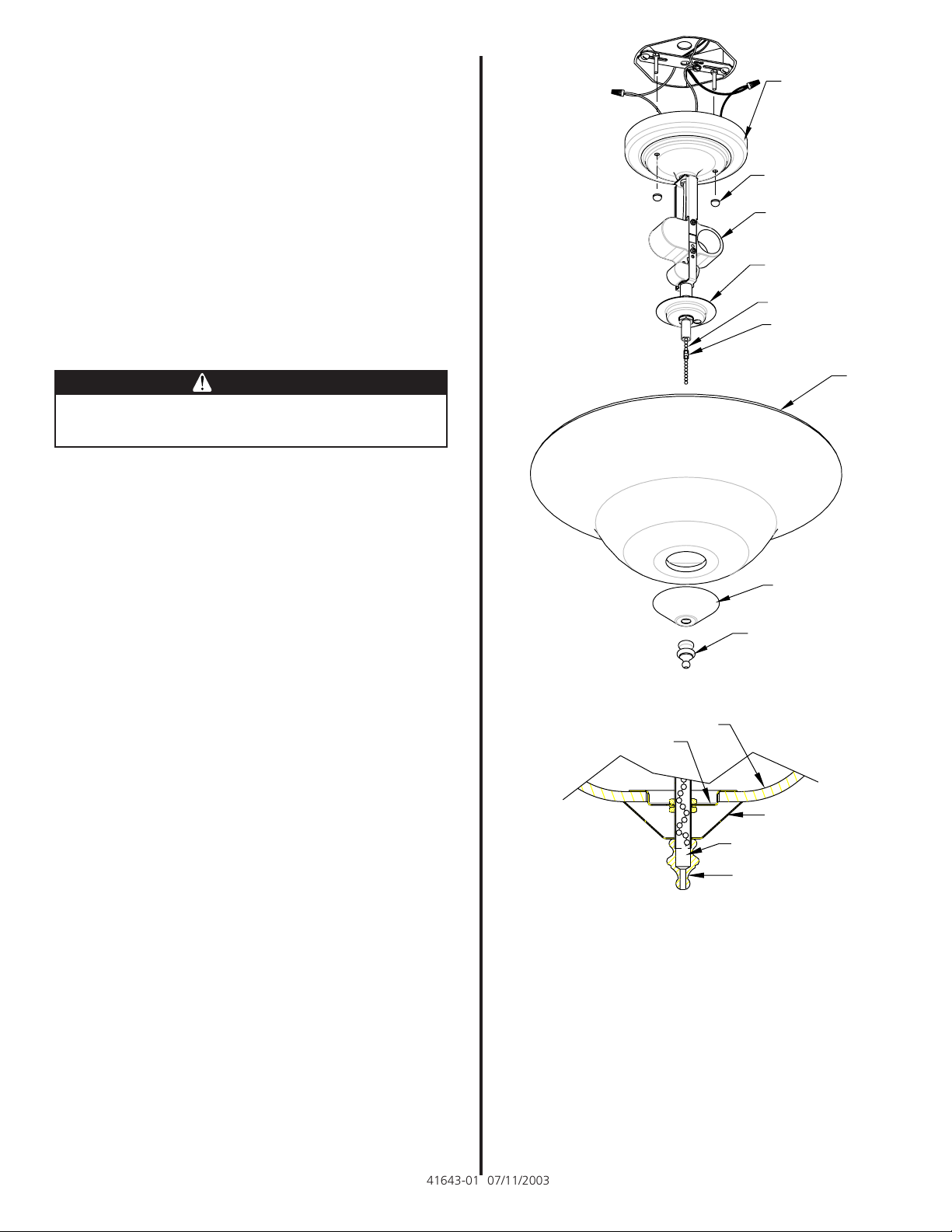
STEP 3: Fixture Assembly - Ceiling Light
NOTE: Refer to Figure 3 for the steps below.
1. Assemble the light fixture to the hanger bracket by
placing the holes in the canopy over the two 8-32”
screws protruding from the hanger bracket.
2. While holding the canopy against the ceiling, install
the two decorative nuts over the two 8-32”screws
and tighten securely.
NOTE: It may be necessary to adjust the screw length
from the hanger bracket by turning the screws out of
the bracket. If this is necessary, reassemble the fixture
by completing Step 3 sub-steps 1 and 2 above.
CANOPY
DECORATIVE
NUTS
LAMPHOLDER
UPPER CAP
UPPER LIGHT PULL
CHAIN
BREAKAWAY
CONNECTOR
GLOBE
BOTTOM CAP
FINIAL
FIGURE 3
3. Install two 60 watt maximum type A-19 bulbs into
the lamp sockets.
NOTE: Type A-19 bulbs are Standard Shape, Standard
Size Household Medium Base Incandescent Bulbs.
CAUTION - RISK OF FIRE, USE MAXIMUM 60
WATT TYPE A-19 LAMPS.
STEP 4: Final Assembly - Ceiling Light
NOTE: Refer to Figures 3 and 4 for the steps below.
1. Temporarily turn the power back on at the electrical
panel.
NOTE: If the bulbs do not light, pull the chain,
coming out of the bottom of the light kit, once. The
lights should now be on.
2. With the lights on, go to the electrical panel and
turn the power back off.
3. Remove the lower chain extension from the light
fixture by unhooking it from the breakaway
connector.
NOTE: Do not discard the chain extension you just
removed as it will be needed if the fixture is converted
in the future.
41643-01 07/11/2003
GLOBE
UPPER CAP
BOTTOM CAP
BREAKAWAY
CONNECTOR
FINIAL
FIGURE 4
4. Leave the breakaway connector in place on the
upper chain.
5. Place the glass globe over the pipe nipple and up
against the upper cap.
6. Place the lower cap, without the side grommetted
hole, over the nipple and up against the glass.
7. Place the finial over the threaded pipe and, while
letting the chain and plastic connector retract into
the pipe, tighten the finial securely. Refer to Figure
4 for further clarification.
8. Turn the power back on at the electrical panel.
Page 3

CEILING FAN LIGHT KIT
SECTION:
CAUTIONS
• Read entire text carefully before beginning
installation and save these instructions.
• Should you desire to change the unit over to
a different style mounting, you will need to
follow these instructions to convert from one
installation style to another.
• To reduce the risk of electrical shock, install
this light kit only on listed Hunter ceiling
fans type A through Z.
WARNING
• To avoid possible electrical shock, before installing light fixtures, disconnect power by
turning off the circuit breakers both to the
outlet box and to its associated wall switch
location. If you cannot lock the circuit breakers in the off position, securely fasten a
prominent warning device, such as a tag, to
the service panel.
• This fixture must be mounted to an approved
outlet box that is directly supported by the
building structure.
• All wiring must be in accordance with national and local electrical codes and ANSI/
NFPA 70. If you are unfamiliar with wiring,
you should use a qualified electrician.
STEP 2: Wiring the Light Kit - Ceiling Fan
1. Remove the bottom switch housing cover from the
ceiling fan.
Note: If your Hunter fan has a remote control or a
removable switch housing, follow the supplemental
instructions supplied with this light kit for that
installation.
2. Using approved wire connectors:
* Connect the white wire from the light fixture to the white
supply wire coming out of the ceiling fan; and
* Connect the black wire from the light fixture to the black
with white striped wire coming out of the ceiling fan.
3. Spread the electrical splices so that the black wires
are on one side of the outlet box and the white wires are on
the other side.
FAN SWITCH
HOUSING
FAN MOUNTING
PLATE
LAMPHOLDER
UPPER CAP
UPPER CHAIN (LIGHT)
STEP 1: Fixtur e Conversion - Ceiling Fan Light
Kit
NOTE: Refer to Figure 3 for the steps below .
1. To install the light fixture in the ceiling fan installation, you must first remove the canopy that comes installed on the ceiling light fixture and replace it with the
fan mounting plate.
2. Loosen the nut inside the canopy and remove the
nut, the lock washer and the ground wire.
3. Locate and install the fan mounting plate over the
pipe nipple as shown in Figure 3.
4. Install the lock washer and nut and tighten securely.
NOTE: It is not necessary to inst all the ground wire onto
the fan light kit, as it is not used for grounding in the fan
installation.
CAUTION
Be sure no bare wire or wire strands are visible after making
connections.
BREAKAWAY CONNECTOR
LIGHT CHAIN
EXTENSION
GLOBE
LOWER CAP
FINIAL
FIGURE 5
41695-01 5/17/2004
Page 4

STEP 3: Mounting the Light Kit - Ceiling Fan
IMPORT ANT INST ALLA TION INFORMA TION: Before
mounting the light kit to your ceiling fan, locate and install
the lockwashers included in the light kit sack parts onto the
screws identified below in Sub-step 2.
1. Align the holes in the fan mounting plate with the mounting
holes in the switch housing.
2. Attach the light kit to the switch housing, using the screws
provided with the fan. Tighten securely.
Warning: Failure to ensure that all fasteners are
secure could result in the switch housing/light
kit assembly falling.
3. Install two 60 watt maximum type A-19 bulbs into the
lamp sockets.
NOTE: T ype A-19 bulbs are Standard Shape, Standard
Size Household Medium Base Incandescent Bulbs.
CAUTION - RISK OF FIRE, USE MAXIMUM 60 WATT
TYPE A-19 LAMPS.
STEP 4: Light Kit Final Assembly - Ceiling Fan
NOTE: Refer to Figures 5 and 6 for the steps below .
1. Locate the pull chain extension in the sack parts.
2. Locate the pull chain and breakaway connector for the fan
speed switch on the fan switch housing and attach the
extension from the step above.
3. Direct the fan switch pull chain through the grommetted hole
in the upper cap.
4. Remove the lower chain and breakaway connector from the
light kit by unhooking the breakaway connector and chain
from the light upper pull chain.
NOTE: Do not discard the breakaway connector or the
light chain extension as you will need them to complete
assembly.
5. Place the glass globe over the threaded pipe nipple and up
against the upper cap.
6. Align the grommetted hole on the lower cap with the
grommetted hole on the upper cap and thread the fan pull
chain through the grommetted holes.
7. Place the lower cap with the grommetted hole over the
threaded pipe nipple and up against the glass.
NOTE: T o ensure proper operation, make sure that the
fan pull chain extension does not bind between the lower
and upper cap and the glass globe.
8. Place the finial over the threaded pipe and thread the light
pull chain through the finial.
9. Tighten the finial securely.
10. Reattach the breakaway connector and the light chain
extension to the light pull chain.
11. Return to the fan installation instructions and follow those
instructions for the completion of the fan installation.
FIGURE 6
If you have any problems or questions please contact us via
phone at 901-248-2222 or visit us on the web at
www.Hunterfan.com
41695-01 5/17/2004
Hunter Fan Company
2500 Frisco Avenue
Memphis, TN 38114
USA
© 2004 Hunter Fan Co. 5/17/2004
 Loading...