

HunterDouglas Silhouette Duolite Installation Operation Care
UltraGlide® 2
PowerView
™
Motorization
Silhouette® Duolite™ Window Shadings
UltraGlide 2 Click and Walk Away™ and
PowerView Motorization Operating Systems
Installation • Operation • Care

CONTENTS
Questions?
Call the Hunter Douglas Customer Information Center at
1-888-501-8364.
© 2016 Hunter Douglas. All rights reserved. All trademarks used herein are the property of Hunter Douglas or
their respective owners.
Getting Started:
Product Views ................................................................................... 1
Tools and Fasteners Needed .............................................................. 2
Installation:
Installation Overview ......................................................................... 3
STEP 1: Mount the Installation Brackets ............................................. 3
Mount the Installation Brackets — Inside Mount ............................. 4
Mount the Installation Brackets — Outside Mount .......................... 6
STEP 2: Install the Shading ............................................................... 8
Mount the Headrail ........................................................................ 8
Attach the Dust Cover (Optional)..................................................... 8
STEP 3: PowerView
™
Only — Connect the Power Source ................... 9
STEP 4: Install the Optional Back Cover (If Applicable) ....................... 12
Operation:
Operate the Shading ....................................................................... 13
UltraGlide
®
2 Click and Walk Away™ ................................................. 13
PowerView Motorization................................................................... 14
Troubleshooting .............................................................................. 18
Care:
Removing the Shading..................................................................... 23
Cleaning Procedures ....................................................................... 23
Child Safety:
Warning .........................................................................................25
PowerView Declarations .............................................................26
Warranty ............................................................................ Back Cover
GETTING STARTED
1
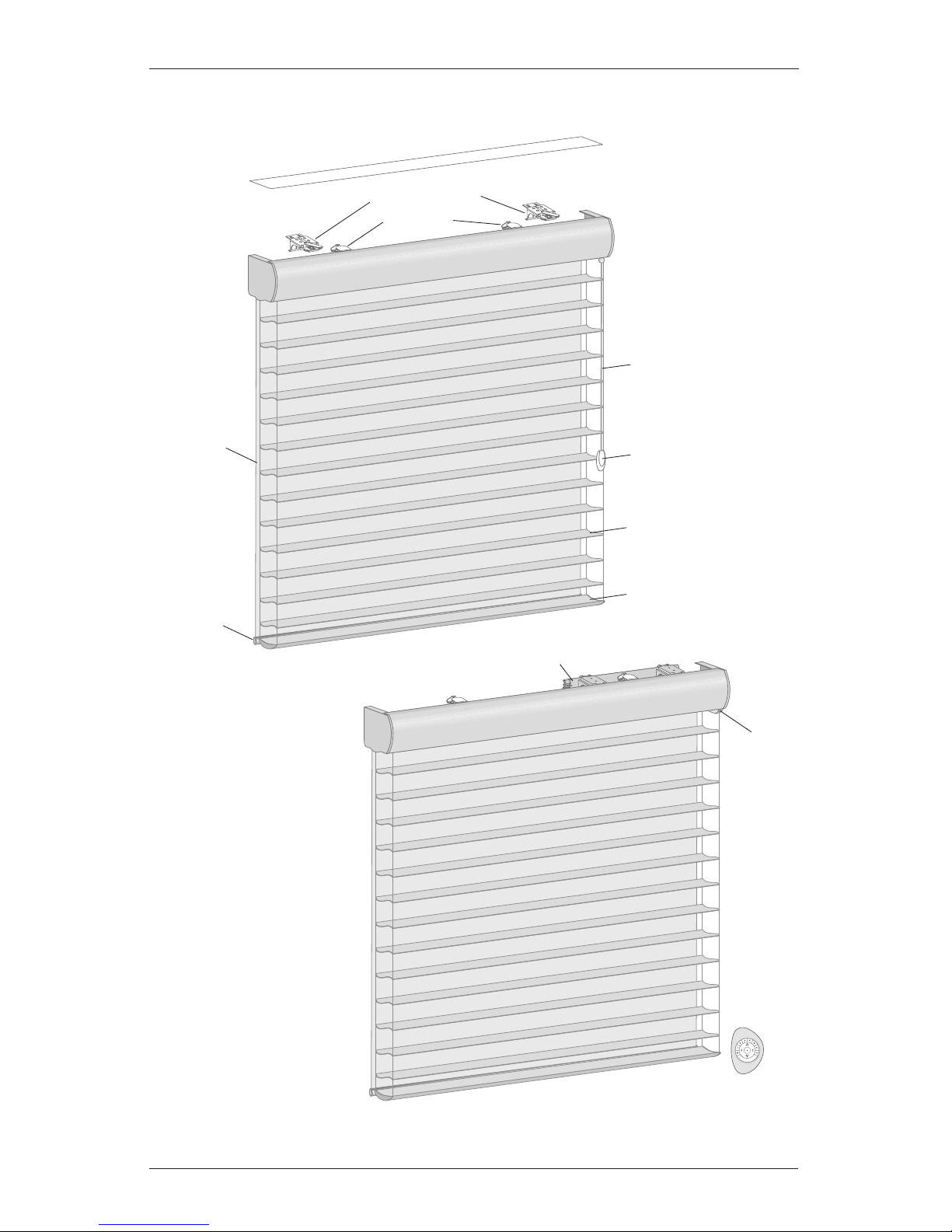
Product Views
Headrail
Optional Dust Cover
Installation Brackets
Limit Stops
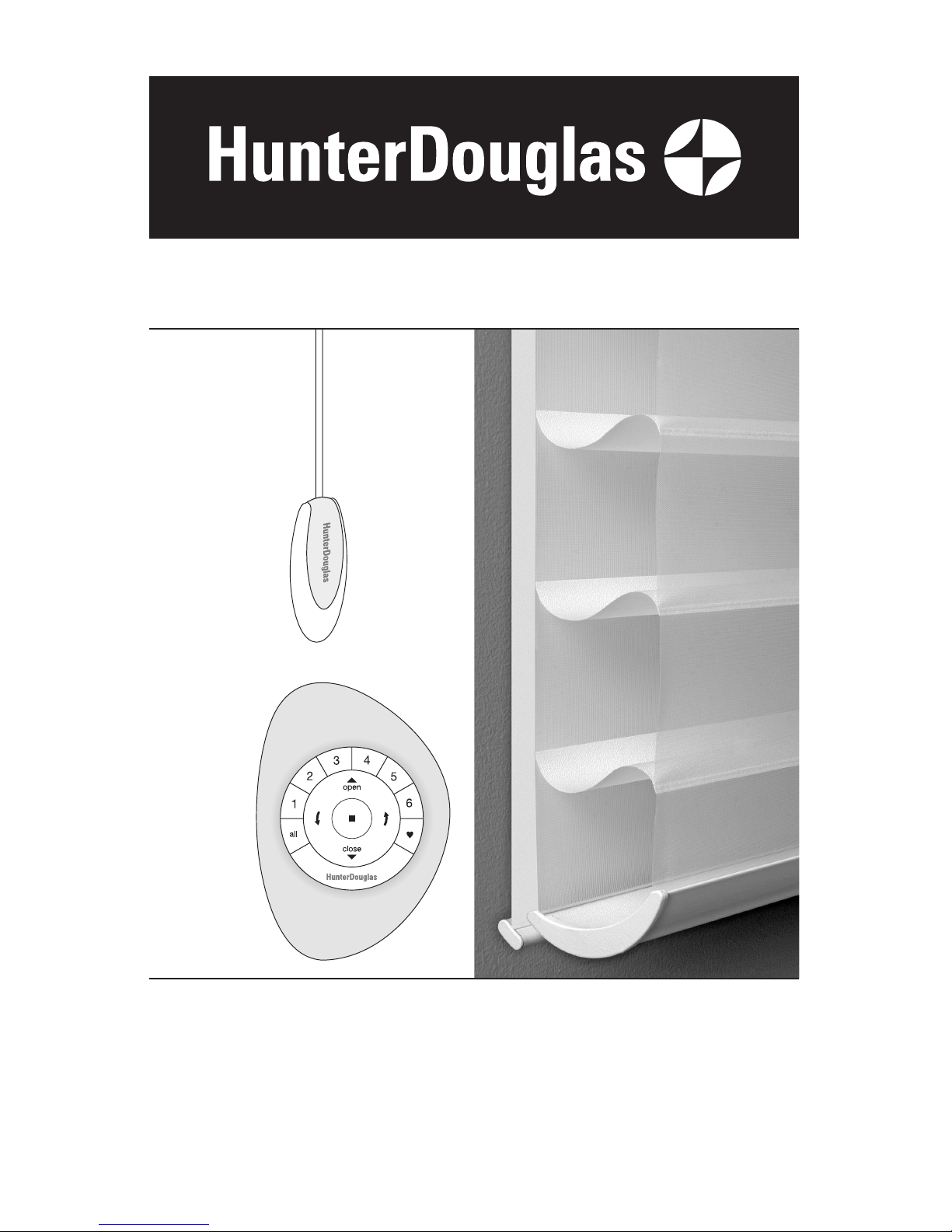
Remote
Roller Shade
Bottom Rail
Rear
Roller Shade
Tassel
Cord
Front Shading
Shading
Bottom Rail
Tassel
Manual
Control
Button
Battery Wand
PowerView
™
Motorization
UltraGlide
®
2
2
GETTING STARTED
Thank you for purchasing Hunter Douglas Silhouette® window shadings. With proper installation,
operation, and care, your new shadings will provide years of beauty andperformance.
Please thoroughly review this instruction booklet before beginning the installation. If your
shading has a protective plastic cover on the fabric-covered headrail, keep the plastic in place
until the shading is installed.
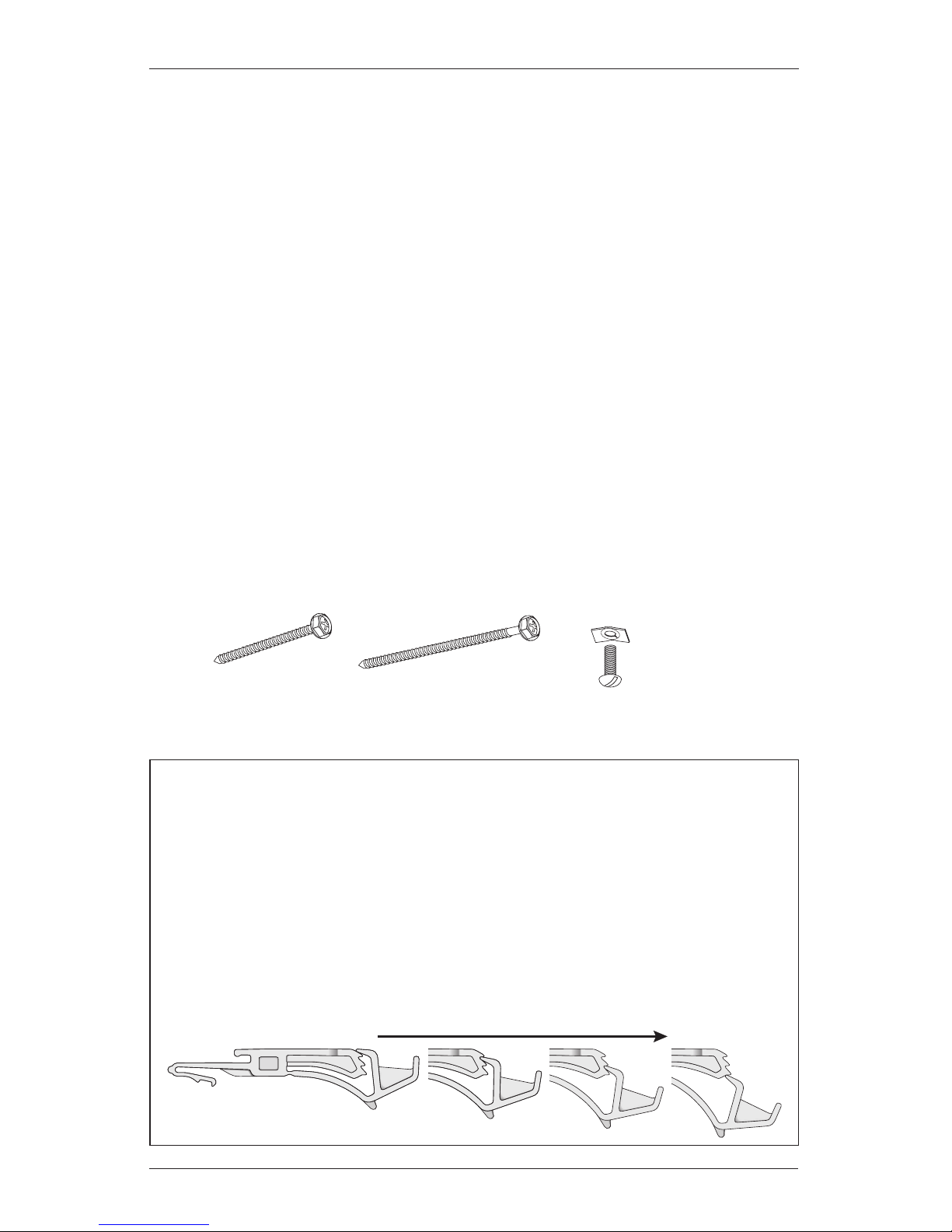
Tools and Fasteners Needed
Flat blade and Phillips screwdrivers Level (laser level is recommended)
Measuring tape and pencil Pliers
Power drill,
3
/32" drill bit,
and
1
/4" hex driver
Scissors (heavy-duty)
In addition, you will need fasteners designed to work with your specific mounting surface(s).
#6 Hex Head Screws (Provided). Two 1
1
/2" screws are provided per installation bracket.
Longer #6 Hex Head Screws (Not Provided). If using spacer blocks, use #6 screws long
enough for a secure attachment.
Speed Nuts and Screws (Provided). Extension brackets come with screws and speed nuts.
Drywall Anchors (Not Provided). Use drywall anchors when mounting into drywall.
#6 x 11/2"
Hex Head Screw
(Provided)
Speed Nut
and Screw
(Two Provided with
Each Extension Bracket)
Longer #6 Hex Head Screw
for Use with Spacer Blocks
(Not Provided)
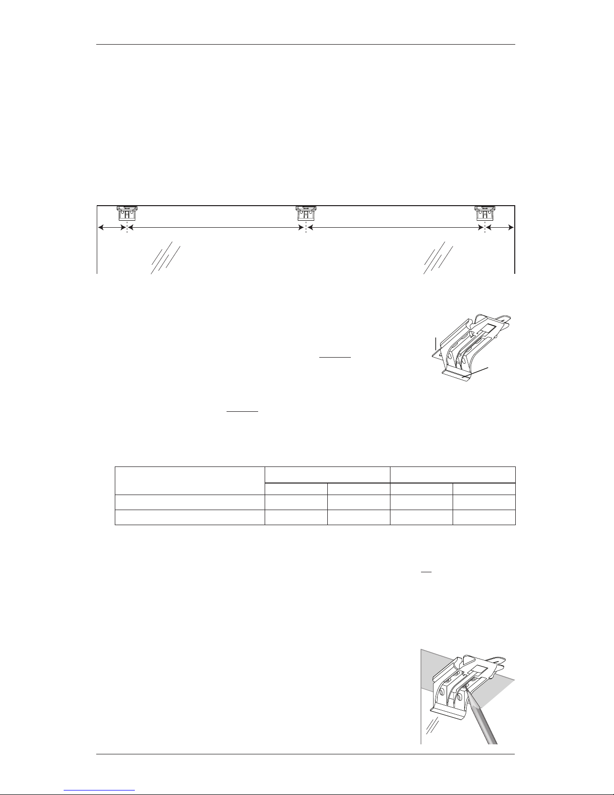
Importance of Limit Stops on Silhouette Window Shadings
Limit stops serve as the upper travel limit for the bottom rail, preventing it from rotating
around the fabric roll. Limit stops are located 6" from the ends of the headrail or are
centered on shadings less than 36" wide.
When a shading is made, the limit stops are adjusted according to the size of the fabric
roll. Occasionally, this adjustment changes during shipping or installation. If this happens,
problems can be fixed by readjusting the limit stops. See page 20 in the Troubleshooting
section if shading operation is difficult or if the bottom rail rotates around the fabric roll.
Shown below are the four possible positions of limit stops for large to small fabric rolls.
Large Fabric Roll Small Fabric Roll
INSTALLATION
3
Installation Overview
To install your shading, you will need to perform the following four steps:
STEP 1: Mount the Installation Brackets
STEP 2: Install the Shading
STEP 3: PowerView
™
Only: Connect the Power Source
STEP 4: Install the Optional Back Cover (If Applicable)
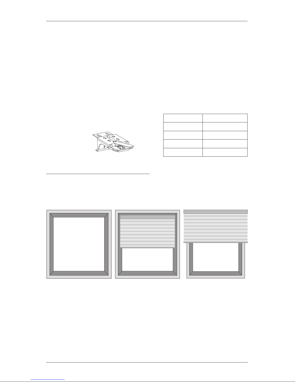
STEP 1: Mount the Installation Brackets
The number of installation brackets required
varies with shading width, as shown in thetable.
Mounting Types and Window Terminology
If the installation brackets are mounted correctly, the rest of the installation process follows
easily. To prepare for this important first step, review the mounting types and basic window
terminology illustrated below.
Refer to the appropriate page below based on your order:
Inside Mount — Page 4
Outside Mount — Page 6
Outside Mount
Shading mounts
outside window
opening.
Inside Mount
Shading fits within
window opening.
Collectively, the sill and
jambs are called the
“window casement.”
Molding
Head Jamb
Sill
Jamb Jamb
Width Brackets Required
18" – 26" 2
26
1
/8" – 47" 3
47
1
/8" – 68" 4
68
1
/8" – 72" 5
Installation
Bracket
INSTALLATION
4
Mount the Installation Brackets — Inside Mount
Mark 2" from each jamb for bracket location.
If more than two installation brackets came with your order, space additional bracket(s)
between the two end brackets and mark their location. Mount into wood whenever
possible.
For PowerView
™
shadings with battery wand, allow a minimum of 17" between bracket
centerlines for the battery wand.
Determine whether or not to remove one or both tabs from the installation brackets.
If using the optional back cover, use pliers to remove both tabs
from the installation brackets.
For PowerView shadings with battery wand without a back cover,
leave both tabs on the brackets. The top tab helps ensure that
there is clearance for the wand.
For all other shadings without a back cover, use pliers to remove the top tab only.
Save any removed top tabs for use as shims when needed.
Review the minimum depth requirements in the table below.
Center the installation brackets on your marks and mark the location of the screwholes.
Allow sufficient rear clearance when positioning the brackets. With no back cover, the
bottom tab provides the necessary clearance (
1
/4") for all systems except PowerView
with battery wand, which requires
7
/8" rear clearance. (Rear clearance is the distance
between the back of the installation bracket and the glass or frame.) Add an extra
1
/4" of
rear clearance if the optional back cover is used.
After positioning the bracket, determine whether the front or
rear set of bracket holes is closer to the center of the casement.
Mark the location of the correct pair of holes.
Window Opening
2" 2"
Operating System Type
Minimum Mounting Depth Fully Recessed Depth
No Back Cover With Back Cover No Back Cover With Back Cover
PowerView with Battery Wand 13/4" 2" 45/16" 49/16"
All Other Systems 1" 1
1
/4" 313/16" 41/16"
Top
Tab
Bottom
Tab
INSTALLATION
5
Use a level to check that the mounting surface is level. Shim the brackets, if necessary,
using the top tabs that were removed from the brackets.
Use a
3
/32" drill bit to drill holes for the mounting screws.
CAUTION: Use drywall anchors when mounting into drywall.
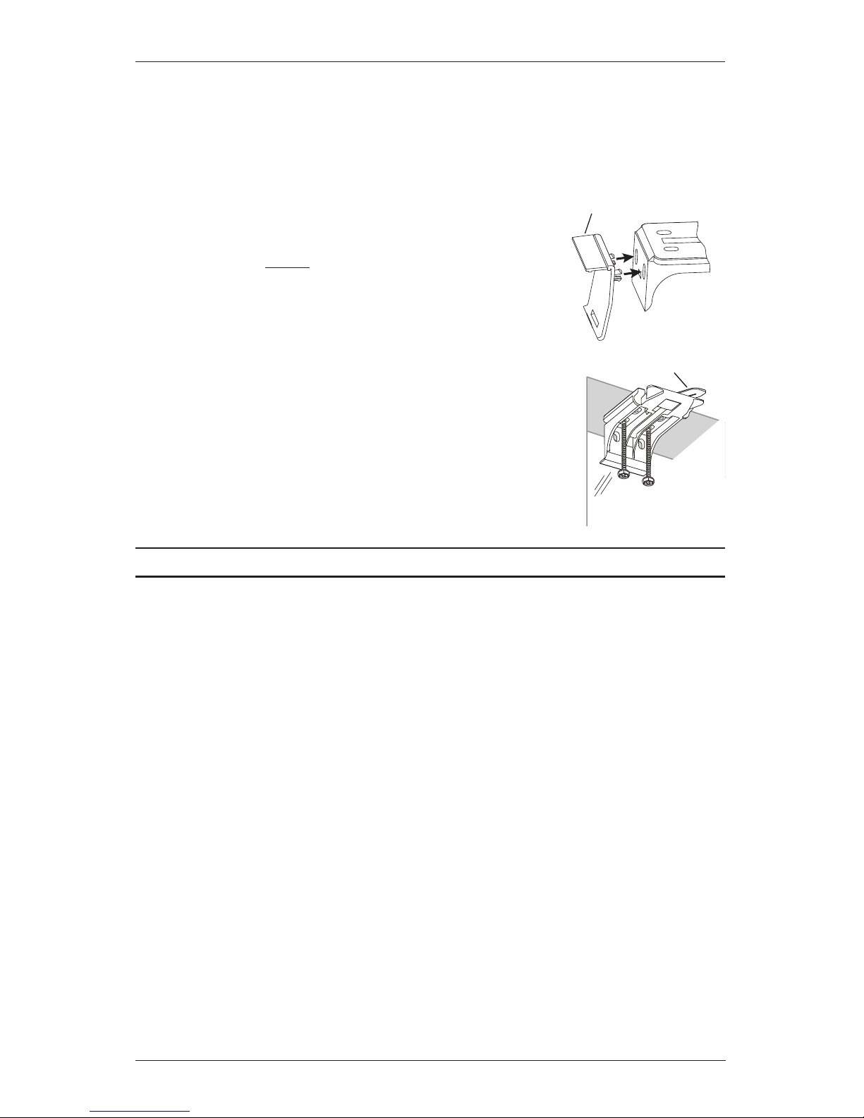
If you received a back cover, attach the back cover brackets
to the installation brackets.
For shadings without battery wand(s), first remove the
top tab from the back coverbracket.
Snap the prongs on the back cover brackets into the
holes on the back of the installation brackets.
Attach the installation brackets using the screws provided.
NOTE: Do not overtighten the screws. Check to ensure the
lever can be moved easily side to side. If the lever is not moving
easily, loosen the screws in one-eighth turn increments until it
can be moved easily.
IMPORTANT: The front edges of the installation brackets must be
level and aligned to eachother.
Proceed to “STEP 2: Install the Shading” on page 8.
Lever
Installation
Bracket
Back
Cover
Bracket
Removable Tab
INSTALLATION
6
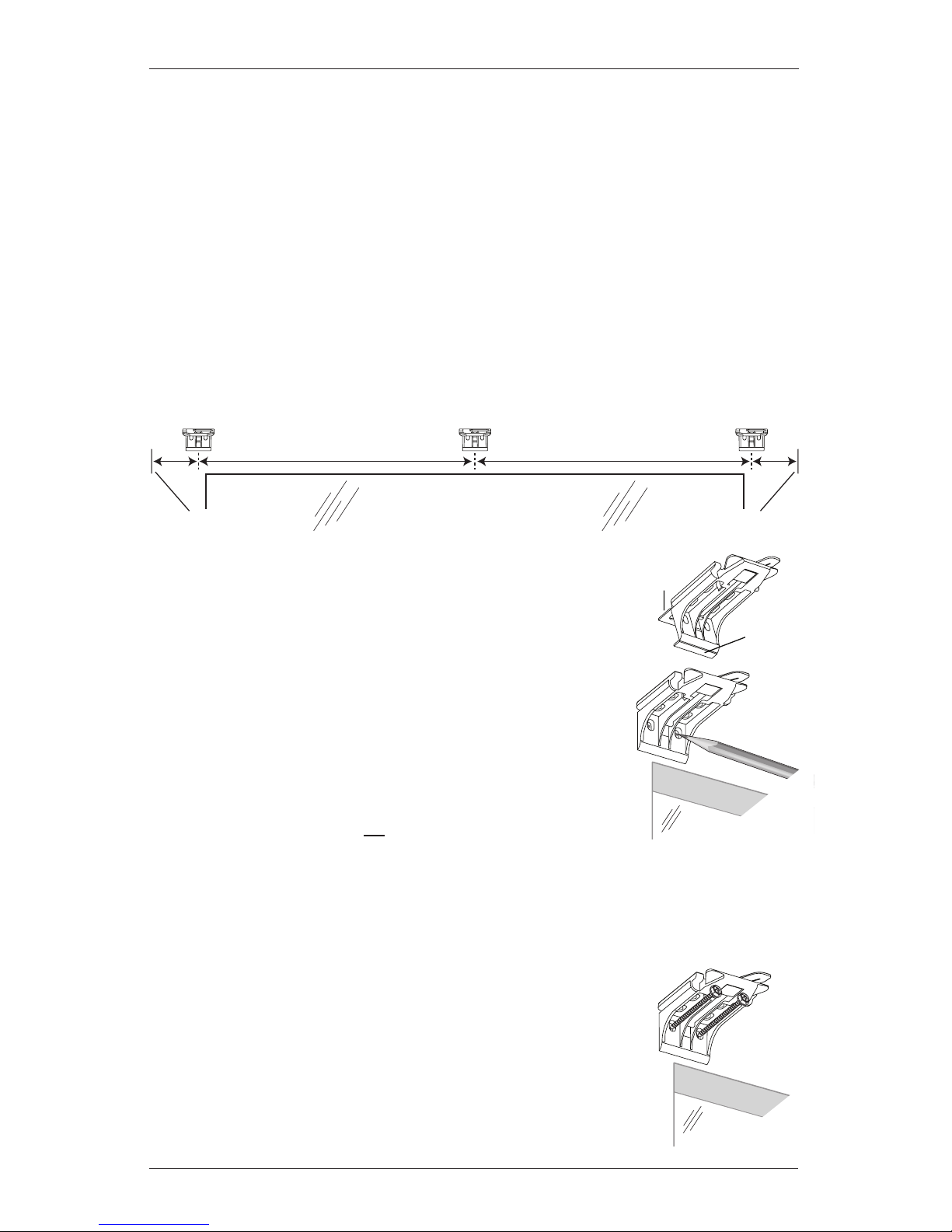
Mount the Installation Brackets — Outside Mount
Center the headrail over the window opening at the desired height. Use a pencil to lightly
mark each end of the headrail.
Alternatively, measure the width of the headrail and use that width to mark the headrail
end points over the window opening.
Mark 2" from each of the headrail end marks for bracket location.
If more than two installation brackets came with your order, space additional bracket(s)
between the two end brackets and mark their location. Mount into wood whenever
possible.
For PowerView
™
shadings with battery wand, allow a minimum of 17" between bracket
centerlines for the battery wand.
Use pliers to break off both the top and bottom tabs from the
installation brackets.
Center the installation brackets on your marks and mark the
location of the screw holes.
A minimum 1
1
/8" flat vertical height is required to mount
the installation brackets.
Position the top of the installation brackets at the desired
height of the shading. The brackets must be level and aligned.
CAUTION: The rear of the blocks/brackets must be flush against
a flat mounting surface. Do not mount brackets oncurved molding.
IMPORTANT: Additional clearance is required for PowerView shadings with battery wand.
See “Additional Clearance with Spacer Blocks” on page 7.
Use a
3
/32" drill bit to drill holes for the mounting screws.
CAUTION: Use drywall anchors when mounting into drywall.
If no additional clearance is required, attach the installation brackets
directly to the mounting surface using the screws provided.
IMPORTANT: The front edges of the installation brackets must be
level and aligned to eachother.
Window Opening
2" 2"
Headrail End Mark Headrail End Mark
Top
Tab
Bottom
Tab
INSTALLATION
7
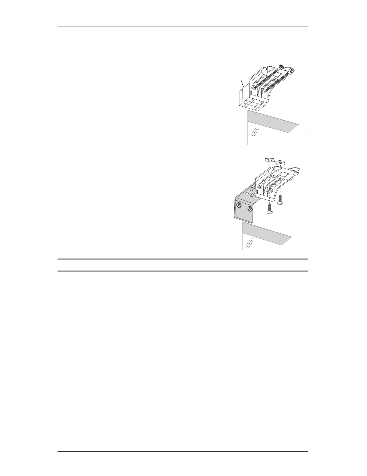
Spacer
Blocks
Longer
Screws
11/2" Maximum
Added Clearance
Extension
Bracket
Speed Nuts
Screws
Additonal Clearance with Spacer Blocks
NOTE: A minimum of 3/4" additional clearance is required for PowerView™ shadings with
battery wand.
If using
1
/4" or 1/2" spacer blocks, attach the spacer block(s)
and installation bracket to a flat vertical mounting surface
with #6screws long enough for asecure installation.
IMPORTANT: The solid side of the spacer blocks must face
toward the mounting surface.
Additonal Clearance with Extension Brackets
If using extension brackets, attach each extension
bracket to the mounting surface using the screws
provided.
Attach an installation bracket to the underside of
each extension bracket using the provided screws
and speed nuts.
NOTE: The maximum amount of added clearance
using extension brackets is 3".
Proceed to “STEP 2: Install the Shading” on page 8.
INSTALLATION
8
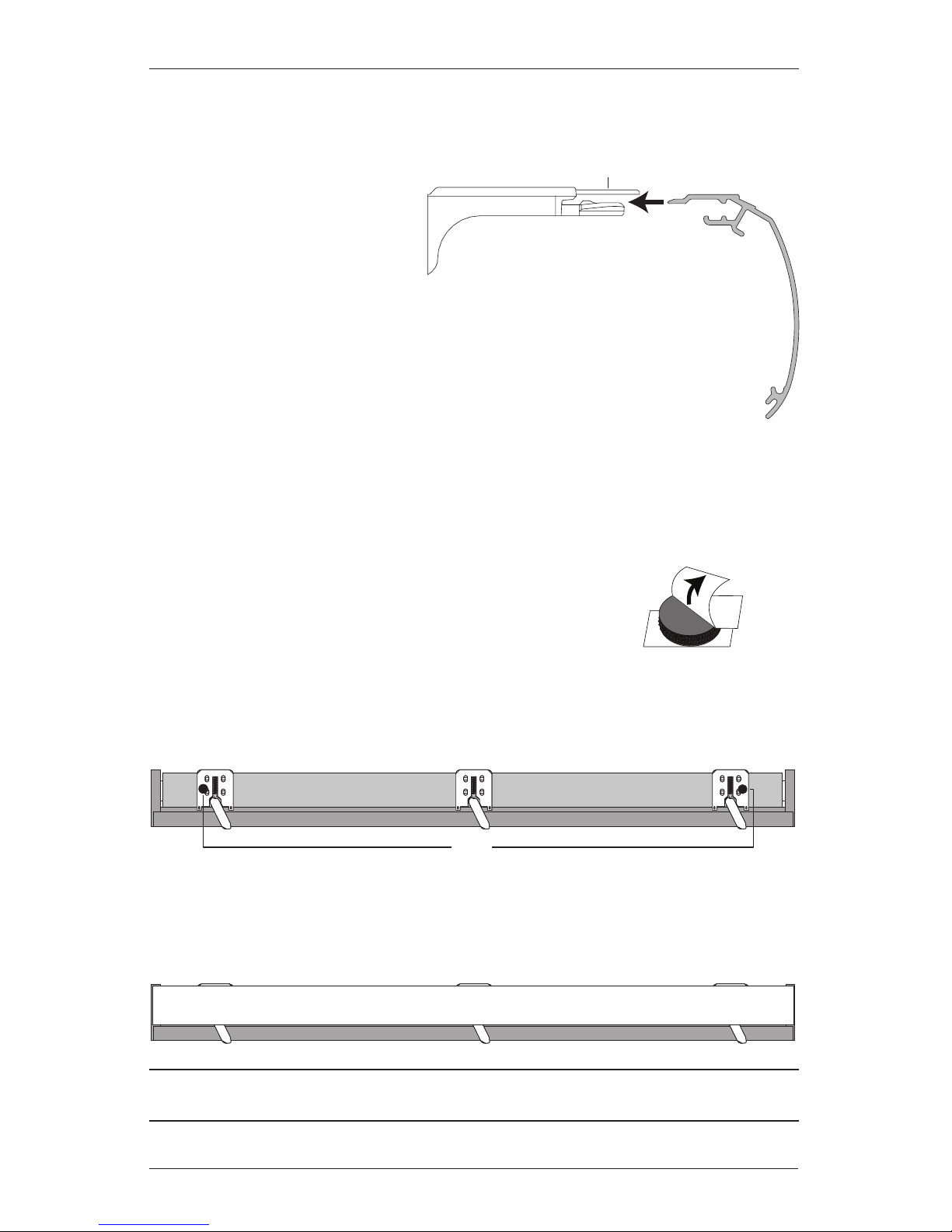
STEP 2: Install the Shading
Mount the Headrail
Peel back the protective covering
from the top of the Palette
®
fabriccovered headrail. Leave the rest
of the protective covering on the
front of the headrail.
Position the shading so that the front faces you.
Slide the headrail into the installation brackets so the edge of the headrail is
between the lever and the bracket, asshown.
Firmly push the headrail into each bracket until it clicks and the lever snaps
to the right side of the bracket.
IMPORTANT: Carefully pull on the headrail at each bracket to ensure it is installedsecurely.
Completely remove the protective covering from the Palette fabric-covered headrail.
Attach the Dust Cover (Optional)
The dust cover can be used with outside mounts to protect the top of
the headrail from exposure.
Cut the dust cover to desired width.
Remove the paper backing on one side of the hook and loop fastener dots.
Apply the dots to the installation brackets on each end of theshading.
Remove the remaining paper backing from the dots.
Center the dust cover over the top of the shading, above the dots, and press the dust cover
down onto the dots.
UltraGlide® 2 shadings only: Proceed to
“STEP 4: Install the Optional Back Cover (If Applicable)” on page 12.
Headrail
Installation Bracket
Lever
Slide the Headrail
Between the Lever
and the Bracket
Remove
Paper
Backing
Overhead View
No Dust Cover
Dots
Dust Cover Installed
 Loading...