

Page 1
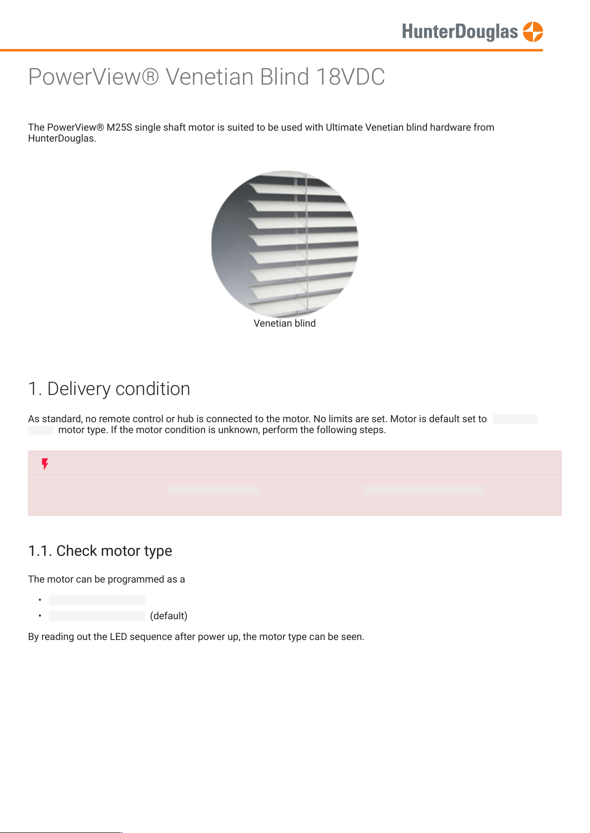
The PowerView® M25S single shaft motor is suited to be used with Ultimate Venetian blind hardware from
As standard, no remote control or hub is connected to the motor. No limits are set. Motor is default set to
The motor can be programmed as a
IMPORTANT
The motor type (default set to
25mm Venetian blind
), has to be changed to
Venetian blind 16 or 25mm
type. Use the
PowerView® Programmer
software tool to change.
MANUAL
PowerView® Venetian Blind 18VDC
HunterDouglas.
Venetian blind
1. Delivery condition
blind motor type. If the motor condition is unknown, perform the following steps.
1.1. Check motor type
• 16mm Venetian blind
• 25mm Venetian blind (default)
Venetian
By reading out the LED sequence after power up, the motor type can be seen.
Page 1 of 22 version: 1.1
Page 2
This procedure will erase all limits stored in the volatile motor memory. It will not clear the Network ID and Group
assignments. Completing an End limits reset will prevent a PowerView® remote or App from operating a window covering
Note
This procedure can be skipped for a fresh out of the box motor.
The motor will jog 2x when receiving any PowerView® command (e.g. Pressing the manual control button on the motor),
to conrm no limits are set.
MANUAL
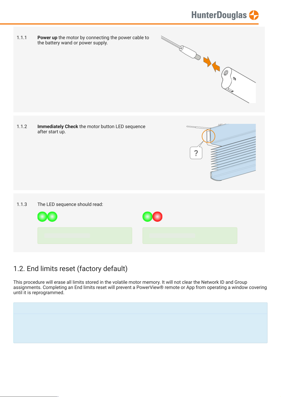
1.1.1 Power up the motor by connecting the power cable to
the battery wand or power supply.
1.1.2 Immediately Check the motor button LED sequence
after start up.
1.1.3 The LED sequence should read:
16mm Venetian blind
1.2. End limits reset (factory default)
until it is reprogrammed.
25mm Venetian blind
Page 2 of 22 version: 1.1
Page 3
MANUAL
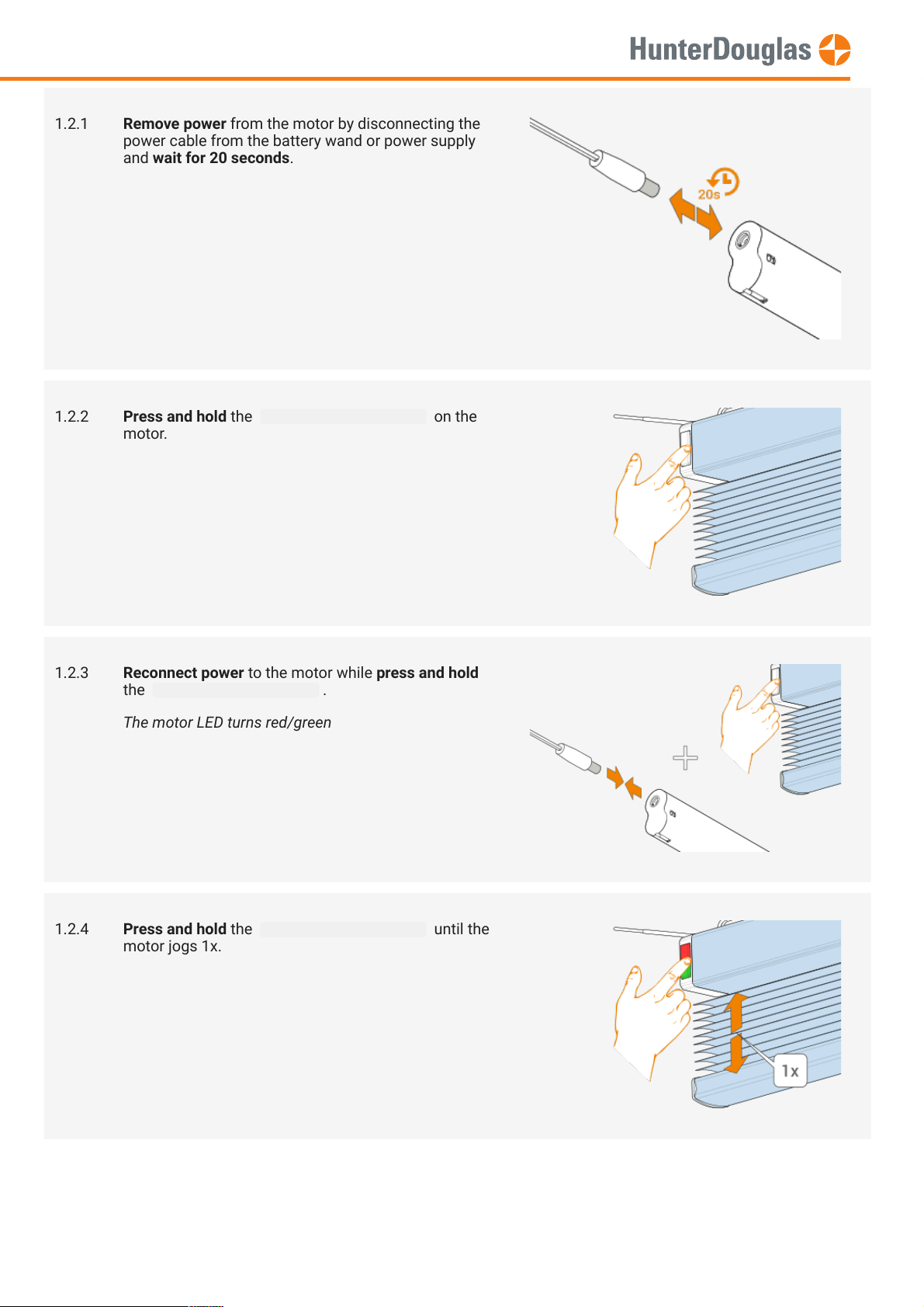
1.2.1 Remove power from the motor by disconnecting the
power cable from the battery wand or power supply
and wait for 20 seconds.
1.2.2 Press and hold the manual control button on the
motor.
1.2.3 Reconnect power to the motor while press and hold
the manual control button .
The motor LED turns red/green
1.2.4 Press and hold the manual control button until the
motor jogs 1x.
Page 3 of 22 version: 1.1
Page 4
This procedure will erase all network data stored in the motor, including Network ID and Group assignments. It will not
clear the end limits. Completing a Network reset will prevent a PowerView® remote or App from operating the window
covering until it is reprogrammed.
A PowerView® remote can control up to 6 individual groups of blinds (buttons 1 to 6 at the top of the remote). The
MANUAL
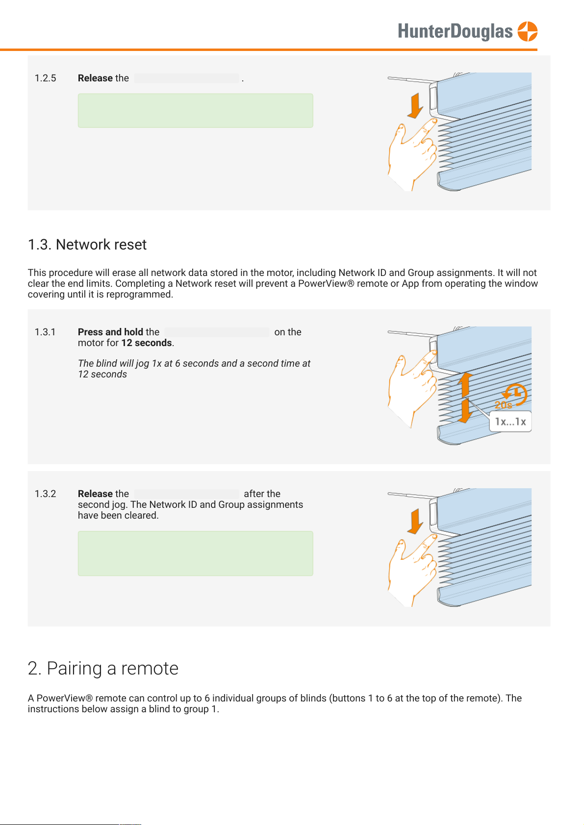
1.2.5 Release the manual control button .
The end limits have been cleared.
1.3. Network reset
1.3.1 Press and hold the manual control button on the
motor for 12 seconds.
The blind will jog 1x at 6 seconds and a second time at
12 seconds
1.3.2 Release the manual control button after the
second jog. The Network ID and Group assignments
have been cleared.
The Network ID and Group assignments have
been cleared.
2. Pairing a remote
instructions below assign a blind to group 1.
Page 4 of 22 version: 1.1
Page 5
IMPORTANT
Watch out to perform steps 2.4 and 2.5 within 3 seconds!
MANUAL
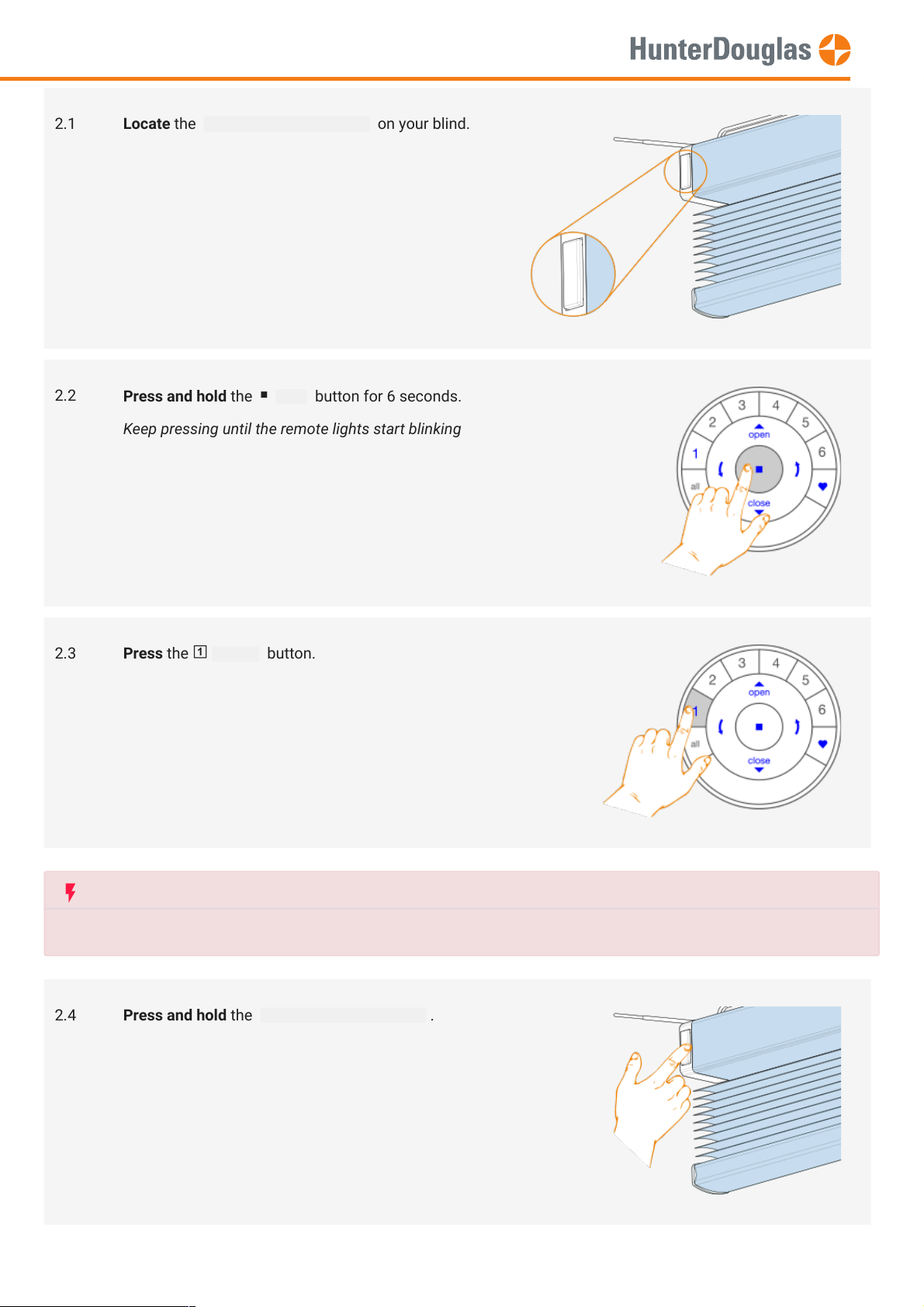
2.1 Locate the manual control button on your blind.
2.2
2.3
Press and hold the stop button for 6 seconds.
Keep pressing until the remote lights start blinking
Press the group1 button.
2.4 Press and hold the manual control button .
Page 5 of 22 version: 1.1
Page 6

IMPORTANT
Reversing motor direction is only possible with a fresh out of the box motor (no limits set) or when the end limits are
.
Before any limits are programmed, the motor direction has to be checked and reversed if needed.
If the top or bottom limit is already set, and the motor direction has to be reversed, perform a
reset
before continuing.
IMPORTANT
Watch out to perform steps 3.1.1 and 3.1.2 within 3 seconds!
MANUAL
2.5
2.6 Release the manual control button .
Press the open button.
The blind will jog 1x
2.7
Press and hold the stop button for 6 seconds.
Keep pressing until the remote lights stop blinking
The remote will exit programming mode
automatically after 20 seconds.
3. Checking motor direction
3.1. Put motor in program mode
Page 6 of 22 version: 1.1
Page 7
MANUAL
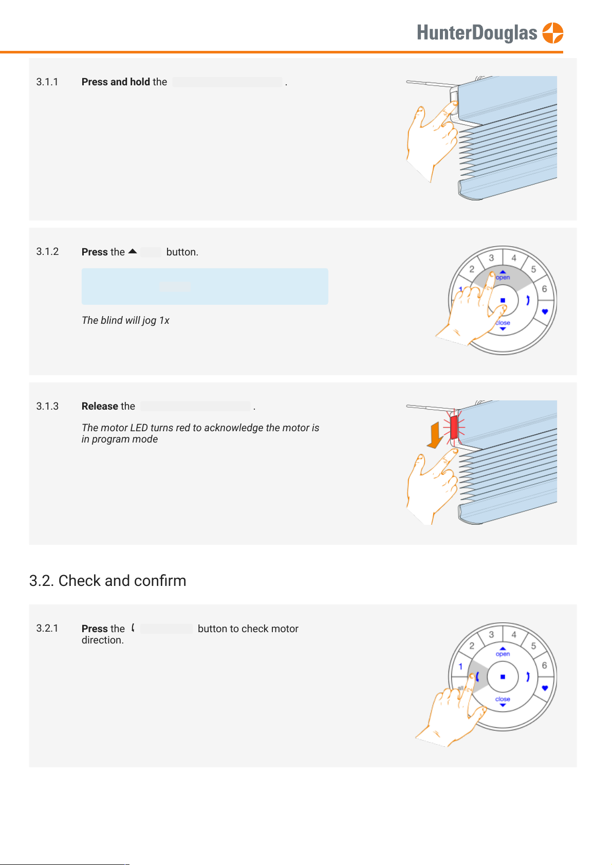
3.1.1 Press and hold the manual control button .
3.1.2
Press the open button.
Make sure group1 on the remote is selected.
The blind will jog 1x
3.1.3 Release the manual control button .
The motor LED turns red to acknowledge the motor is
in program mode
3.2. Check and conrm
3.2.1
Press the arrow down button to check motor
direction.
Page 7 of 22 version: 1.1
Page 8

4. Setting end limits
MANUAL
3.2.2.A
If the blind moves upwards, Press the
stop button.
3.2.2.B
If the blind moves downwards, Press the
stop button and continue with step 4.1.4
Motor direction NOT OK!
3.2.3 Press and hold the manual control button for 1
second to reverse motor direction.
The blind will jog 1x to acknowledge the direction is
reversed
Motor direction OK!
3.2.4 Continue with step 4.1.4
It doesn’t matter if you start with setting the open or the close limit rst. In this description we start with the open (top)
limit.
Page 8 of 22 version: 1.1
Page 9

4.1. Open limit (top)
MANUAL
4.1.1 Press and hold the manual control button .
4.1.2
Press the open button.
Make sure group1 on the remote is selected.
The blind will jog 1x
4.1.3 Release the manual control button .
The motor LED turns red to acknowledge the motor is
in program mode
4.1.4
Use the open , stop and close buttons to
move the blind about 20cm below the headrail.
Page 9 of 22 version: 1.1
Page 10

IMPORTANT
Watch out to perform steps 4.1.6 and 4.1.7 within 3 seconds!
MANUAL
4.1.5
4.1.6
Use the open button to let the blind hit the headrail.
The motor will stop moving.
The motor needs to hit the headrail!
Move the blind to the desired top position with the
open , close and stop buttons.
Always approach the desired top limit moving
upwards.
4.1.7
Press and hold the stop button for 6 seconds.
DO NOT select a group on the remote!
Keep pressing until the remote lights start blinking
4.1.8 Press and hold the manual control button .
Page 10 of 22 version: 1.1
Page 11

MANUAL
4.1.9
4.1.10 Release the manual control button .
Press the open button.
The blind will jog 1x to acknowledge the limit is set
The motor LED turns off
4.1.11
4.1.12 The top limit is set!
Press and hold the stop button for 6 seconds.
Keep pressing until the remote lights stop blinking
The remote will exit programming mode
automatically after 20 seconds.
Page 11 of 22 version: 1.1
Page 12

4.2. Close limit (bottom)
Note
To re-position the top limit of the blind, repeat step
4.1 Open limit (top)
.
MANUAL
4.2.1 Press and hold the manual control button .
4.2.2
Press the close button.
Make sure group1 on the remote is selected.
The blind will jog 1x
4.2.3 Release the manual control button .
The motor LED turns red to acknowledge the motor is
in program mode
Page 12 of 22 version: 1.1
Page 13

IMPORTANT
Watch out to perform steps 4.2.6 and 4.2.7 within 3 seconds!
MANUAL
4.2.4
4.2.5
Use the open , stop and close buttons to
move the blind to the desired bottom position.
Press and hold the stop button for 6 seconds.
DO NOT select a group on the remote!
Keep pressing until the remote lights start blinking
4.2.6 Press and hold the manual control button .
Page 13 of 22 version: 1.1
Page 14

MANUAL
4.2.7
4.2.8 Release the manual control button .
Press the close button.
The blind will jog 1x to acknowledge the limit is set
The motor LED turns off
4.2.9
Press and hold the stop button for 6 seconds.
Keep pressing until the remote lights stop blinking
The remote will exit programming mode
automatically after 20 seconds.
Page 14 of 22 version: 1.1
Page 15

The slat open position is automatically set, by selecting blind type in the
Note
To re-position the bottom limit of the blind, repeat step
4.2. Close limit (bottom)
IMPORTANT
Only
if the slat limit position is not satisfactory, follow below procedure to overwrite and reposition the slat open position.
MANUAL
4.2.10 The bottom limit is set!
5. Slat open position
• 16mm Venetian blind
• 25mm Venetian blind (default)
5.1 Locate the manual control button on your blind.
PowerView® Programmer software tool:
Page 15 of 22 version: 1.1
Page 16

IMPORTANT
Watch out to perform steps 5.4 and 5.5 within 3 seconds!
MANUAL
5.2
5.3
Press the group1 button.
Press the close button to move the blind to the
bottom position.
5.4 Press and hold the manual control button on your
blind.
Page 16 of 22 version: 1.1
Page 17

MANUAL
5.5
Press and hold the arrow up button until the
motor LED turns red.
The motor LED turns red to acknowledge the motor is
in program mode
5.6 Determine the maximum rotation position using the
arrow up , arrow down and stop buttons.
Vanes start to tilt open... ...to 90° and continue... ...until 180° reversed
Page 17 of 22 version: 1.1
Page 18

IMPORTANT
Watch out to perform steps 5.8 and 5.9 within 3 seconds!
MANUAL
5.7
5.8 Press and hold the manual control button on your
Press and hold the stop button for 6 seconds.
DO NOT select a group on the remote!
Keep pressing until the remote lights start blinking
blind.
5.9
Press the arrow up button.
The blind will jog 1x to acknowledge the slat open
position is set
5.10 Release the manual control button .
The motor LED turns off
Page 18 of 22 version: 1.1
Page 19

The motor control button LED gives an indication of the motor status. The LED can ash RED or GREEN. Below you nd an
overview of all possible combinations.
MANUAL
5.11
5.12 The slat open position is set!
Press and hold the stop button for 6 seconds.
Keep pressing until the remote lights stop blinking
The remote will exit programming mode
automatically after 20 seconds.
6. Motor control button LED
Sequence Explanation
After power up
Restart / Start up
Blind type: Venetian 16mm slat
Blind type: Venetian 25mm slat
After Reset
End limits reset (factory default),
see chapter 1.2
Page 19 of 22 version: 1.1
Page 20

MANUAL
Battery operation
Network reset on manual control button
release,
see chapter 1.3. Blind type: Venetian 16mm
slat
Network reset on manual control button
release,
see chapter 1.3. Blind type: Venetian 25mm
slat
Others
Low battery indication (< 11.0V).
The blind will run in slow mode and can only
be send upwards.
Ultra low battery indication (< 8.5V).
The blind will not run anymore. Change the
batteries.
The maximum motor current has been
reached.
E.g. The blind is stuck at an obstacle.
(Continuous)
Steady red LED.
The motor is in program mode (during limit
setting).
Jog sequences Explanation
Page 20 of 22 version: 1.1
Page 21

MANUAL
Jog 1x
Jog 2x
Action conrmed.
Action denied on move command: no limit
set.
Action denied on move command: no valid
close limit set.
Jog 3x
Jog 4x
Action denied on move command: no valid
open limit set.
Action denied on open limit set: open limit is
not referenced (did not hit headrail! See step
4.1.5)
Action denied on limit set: invalid product
height
Page 21 of 22 version: 1.1
Page 22

its products and services, and to discontinue any product or service. Buyers should obtain the latest relevant information before placing orders and
should verify that such information is current and complete. All products (also referred to herein as "components") are sold subject to Hunter Douglas’
terms and conditions of sale supplied at the time of order acknowledgment. Hunter Douglas warrants performance of its components to the
specications applicable at the time of sale, in accordance with its standard warranty terms. Testing and other quality control techniques are used to the
extent Hunter Douglas deems necessary to support this warranty. Except where mandated by applicable law, testing of all parameters of each
component is not necessarily performed. Hunter Douglas assumes no liability for applications assistance or the design of Buyers' products. Buyers are
responsible for their products, applications and interfaces using Hunter Douglas components. To minimize the risks associated with Buyers' products
and applications, Buyers should provide adequate design and operating safeguards. Hunter Douglas does not warrant or represent that any license,
either express or implied, is granted under any patent right, copyright, mask work right, or other intellectual property right relating to any combination,
machine, or process in which Hunter Douglas components or services are used. Information published by Hunter Douglas regarding third-party products
or services does not constitute a license to use such products or services or a warranty or endorsement thereof. Use of such information may require a
license from a third party under the patents or other intellectual property of the third party, or a license from Hunter Douglas under the patents or other
intellectual property of Hunter Douglas. Reproduction of Hunter Douglas information in Hunter Douglas data sheets is permissible only if reproduction is
without alteration and is accompanied by all associated warranties, conditions, limitations, and notices. Hunter Douglas is not responsible or liable for
any altered documentation. Information of third parties may be subject to additional restrictions. Resale of Hunter Douglas components or services with
statements different from or beyond the parameters stated by Hunter Douglas for that component or service voids all express and any implied
warranties for the associated Hunter Douglas component or service and is an unfair and deceptive business practice. Hunter Douglas is not responsible
or liable for any such statements. Buyers acknowledge and agree that they are solely responsible for compliance with all legal, regulatory and safety-
related requirements concerning its products, and any use of Hunter Douglas components in its applications, notwithstanding any applications-related
information or support that may be provided by Hunter Douglas. Buyers represent and agree that they have all the necessary expertise to create and
implement safeguards which anticipate dangerous consequences of failures, monitor failures and their consequences, lessen the likelihood of failures
that might cause harm and take appropriate remedial actions. Buyers fully indemnify Hunter Douglas and its representatives against any damages
arising out of the use of any Hunter Douglas components in safety-critical applications.
MANUAL
Important notice
Page 22 of 22 version: 1.1
 Loading...