

Page 1
This guide will explain step-by-step how to install the PS-18/300 power supply and connect the PowerView® motor wires
on the connection terminals. The following instruction will show you how to:
To install the power supply and for connecting wires to the connection terminal block, following parts and equipment are
MANUAL
PowerView® PS-18/300 power supply
• Install and mount the power supply on a wall
• Correctly set up the wiring of the PowerView® installation
• Connect the wires onto the terminal blocks of the power supply
1. Hardware overview
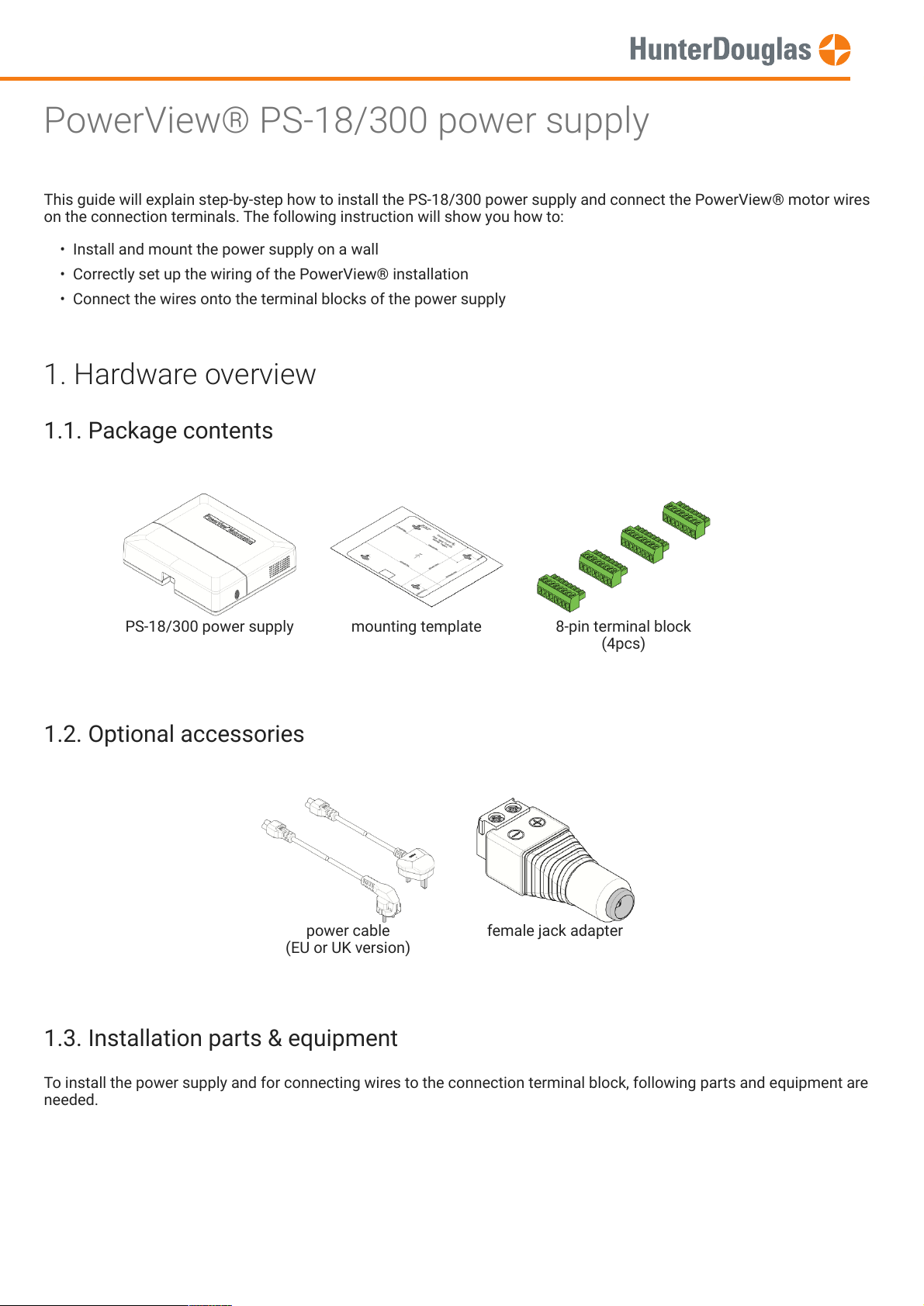
1.1. Package contents
PS-18/300 power supply mounting template 8-pin terminal block
1.2. Optional accessories
power cable
(EU or UK version)
1.3. Installation parts & equipment
(4pcs)
female jack adapter
needed.
Page 1 of 13 version: 1.0
Page 2
The PS-18/300 power supply has been designed to install vertically to a wall. An A4 paper template is available to easily
determine the mounting holes.
Note
In this guide, the power supply will be installed on a concrete wall.
MANUAL
Level hammer drill hammer Set of screwdrivers
Pan head screws (4pcs) wall plugs (4pcs)
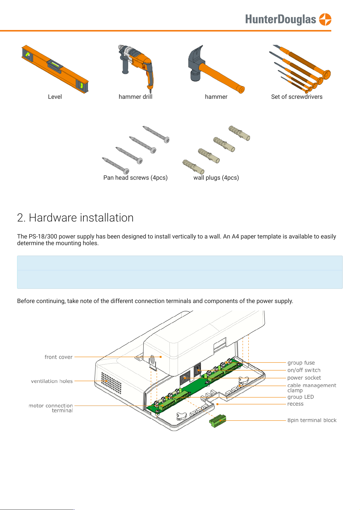
2. Hardware installation
Before continuing, take note of the different connection terminals and components of the power supply.
Page 2 of 13 version: 1.0
Page 3
IMPORTANT
The
ventilation holes
(both sides of the housing) may not be covered. Leave enough free space of the left and right
side.
There are 4 fused motor group connection terminals. Each group is able to deliver max. 4Amps @ 18VDC.
In case of a broken
group fuse
, the
group LED
will not light up when the power supply is powered on.
Always switch off the power supply and disconnect the power cable when installing or making connections.
Make use of the
to neatly align the motor and power cables.
Make sure a
power socket
is nearby (max. 0.5m).
Note
The bare metal connections (18VDC) under the power supply's
front cover
are safe to touch when the power is on.
All 230VAC components are shielded from any possible human or pet contact.
MANUAL
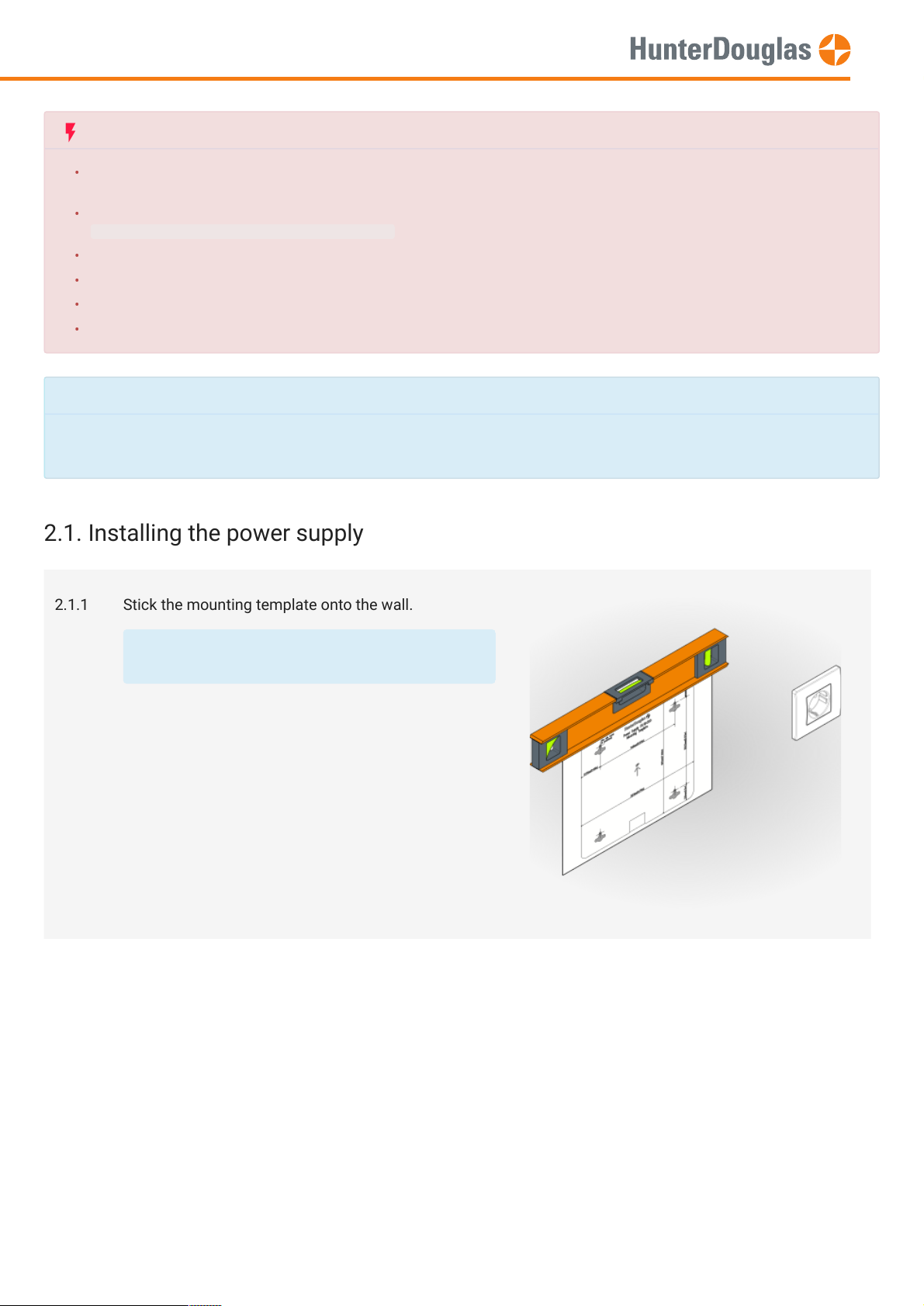
2.1. Installing the power supply
2.1.1 Stick the mounting template onto the wall.
Use a level tool to align the template.
Page 3 of 13 version: 1.0
Page 4
MANUAL
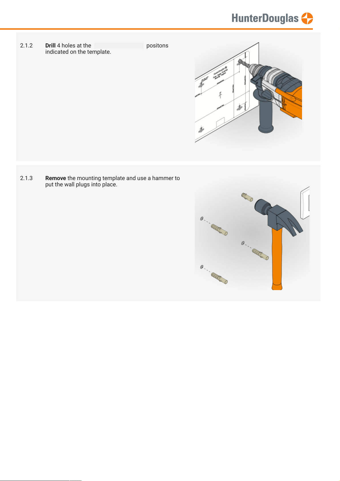
2.1.2 Drill 4 holes at the Pilot hole center positons
indicated on the template.
2.1.3 Remove the mounting template and use a hammer to
put the wall plugs into place.
Page 4 of 13 version: 1.0
Page 5

Remove
IMPORTANT
Make sure the
is set in the
position.
MANUAL
2.1.4 Use a screwdriver to install the screws.
The distance from the wall to the at surface of
the panhead screw is about 3.5mm.
2.1.5 Remove the front cover and mount the power supply
to the wall.
2.2. Connecting cables
the power supply from the wall and disconnect the power cable.
Page 5 of 13 version: 1.0
Page 6
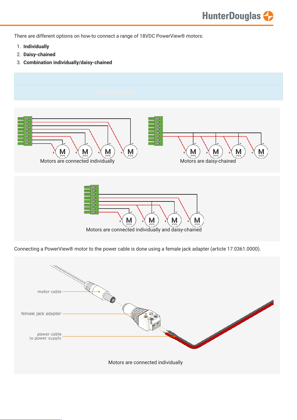
There are different options on how-to connect a range of 18VDC PowerView® motors:
Connecting a PowerView® motor to the power cable is done using a female jack adapter (article 17.0361.0000).
Note
As a general rule of thumb, connect
maximum 4 motors
(1 motor = max. 1Amp power consumption) per terminal block.
MANUAL
1. Individually
2. Daisy-chained
3. Combination individually/daisy-chained
Motors are connected individually Motors are daisy-chained
Motors are connected individually and daisy-chained
Motors are connected individually
Page 6 of 13 version: 1.0
Page 7

IMPORTANT
Depending on the motor count per chain and used wire surface/diameter,
See table below for more information.
MANUAL
Motors are daisy-chained
wire area: 0.5mm² wire length [m.]
1 2 3 4 5 6 7 8 9 10111213 1415161718 1920212223 2425262728 2930
# motors 1
2
3
4
0.1 0.1 0.2 0.3 0.4 0.4 0.5 0.6 0.6 0.7 0.8 0.8 0.9 1 1.1 1.1 1.2 1.3 1.3 1.4 1.5 1.5 1.6 1.7 1.8 1.8 1.9 2 2 2.1
0.1 0.3 0.4 0.6 0.7 0.8 1 1.1 1.3 1.4 1.5 1.7 1.8 2 2.1 2.2 2.4 2.5 2.7 2.8 2.9 3.1 3.2 3.4 3.5 3.6 3.8 3.9 4.1 4.2
0.2 0.4 0.6 0.8 1.1 1.3 1.5 1.7 1.9 2.1 2.3 2.5 2.7 2.9 3.2 3.4 3.6 3.8 4 4.2 4.4 4.6 4.8 5 5.3 5.5 5.7 5.9 6.1 6.3
0.3 0.6 0.8 1.1 1.4 1.7 2 2.2 2.5 2.8 3.1 3.4 3.6 3.9 4.2 4.5 4.8 5 5.3 5.6 5.9 6.2 6.4 6.7 7 7.3 7.6 7.8 8.1 8.4
wire area: 0.75mm² wire length [m.]
1 2 3 4 5 6 7 8 9 10111213 1415161718 1920212223 2425262728 2930
# motors 1
2
3
4
0 0.1 0.1 0.2 0.2 0.3 0.3 0.4 0.4 0.5 0.5 0.6 0.6 0.7 0.7 0.7 0.8 0.8 0.9 0.9 1 1 1.1 1.1 1.2 1.2 1.3 1.3 1.4 1.4
0.1 0.2 0.3 0.4 0.5 0.6 0.7 0.7 0.8 0.9 1 1.1 1.2 1.3 1.4 1.5 1.6 1.7 1.8 1.9 2 2.1 2.1 2.2 2.3 2.4 2.5 2.6 2.7 2.8
0.1 0.3 0.4 0.6 0.7 0.8 1 1.1 1.3 1.4 1.5 1.7 1.8 2 2.1 2.2 2.4 2.5 2.7 2.8 2.9 3.1 3.2 3.4 3.5 3.6 3.8 3.9 4.1 4.2
0.2 0.4 0.6 0.7 0.9 1.1 1.3 1.5 1.7 1.9 2.1 2.2 2.4 2.6 2.8 3 3.2 3.4 3.5 3.7 3.9 4.1 4.3 4.5 4.7 4.9 5 5.2 5.4 5.6
wire area: 1.0mm² wire length [m.]
1 2 3 4 5 6 7 8 9 10111213 1415161718 1920212223 2425262728 2930
# motors 1
2
3
4
0 0.1 0.1 0.1 0.2 0.2 0.2 0.3 0.3 0.4 0.4 0.4 0.5 0.5 0.5 0.6 0.6 0.6 0.7 0.7 0.7 0.8 0.8 0.8 0.9 0.9 0.9 1 1 1.1
0.1 0.1 0.2 0.3 0.4 0.4 0.5 0.6 0.6 0.7 0.8 0.8 0.9 1 1.1 1.1 1.2 1.3 1.3 1.4 1.5 1.5 1.6 1.7 1.8 1.8 1.9 2 2 2.1
0.1 0.2 0.3 0.4 0.5 0.6 0.7 0.8 0.9 1.1 1.2 1.3 1.4 1.5 1.6 1.7 1.8 1.9 2 2.1 2.2 2.3 2.4 2.5 2.6 2.7 2.8 2.9 3 3.2
0.1 0.3 0.4 0.6 0.7 0.8 1 1.1 1.3 1.4 1.5 1.7 1.8 2 2.1 2.2 2.4 2.5 2.7 2.8 2.9 3.1 3.2 3.4 3.5 3.6 3.8 3.9 4.1 4.2
wire area: 1.5mm² wire length [m.]
1 2 3 4 5 6 7 8 9 10111213 1415161718 1920212223 2425262728 2930
# motors 1
2
3
4
0 0 0.1 0.1 0.1 0.1 0.2 0.2 0.2 0.2 0.3 0.3 0.3 0.3 0.4 0.4 0.4 0.4 0.4 0.5 0.5 0.5 0.5 0.6 0.6 0.6 0.6 0.7 0.7 0.7
0 0.1 0.1 0.2 0.2 0.3 0.3 0.4 0.4 0.5 0.5 0.6 0.6 0.7 0.7 0.7 0.8 0.8 0.9 0.9 1 1 1.1 1.1 1.2 1.2 1.3 1.3 1.4 1.4
0.1 0.1 0.2 0.3 0.4 0.4 0.5 0.6 0.6 0.7 0.8 0.8 0.9 1 1.1 1.1 1.2 1.3 1.3 1.4 1.5 1.5 1.6 1.7 1.8 1.8 1.9 2 2 2.1
0.1 0.2 0.3 0.4 0.5 0.6 0.7 0.7 0.8 0.9 1 1.1 1.2 1.3 1.4 1.5 1.6 1.7 1.8 1.9 2 2.1 2.1 2.2 2.3 2.4 2.5 2.6 2.7 2.8
Page 7 of 13 version: 1.0
Page 8

MANUAL
2.2.1 Take note of the polarity to connect the motor
wires on the terminal block.
2.2.2 Connect the wires from an individual or daisy-chained
motor(s) to 1 or more terminal blocks .
ATTENTION.
Watch out for the polarity.
Wrong connection may damage the power
supply.
TIP.
Use good recognizable motor wiring.
E.g. red wire = plus (+) ; black wire = minus (-)
2.2.3 Mount the power supply back to the wall.
Put the terminal block(s) in place on the power
supply.
TIP.
Do not connect unused terminal blocks.
Page 8 of 13 version: 1.0
Page 9
MANUAL
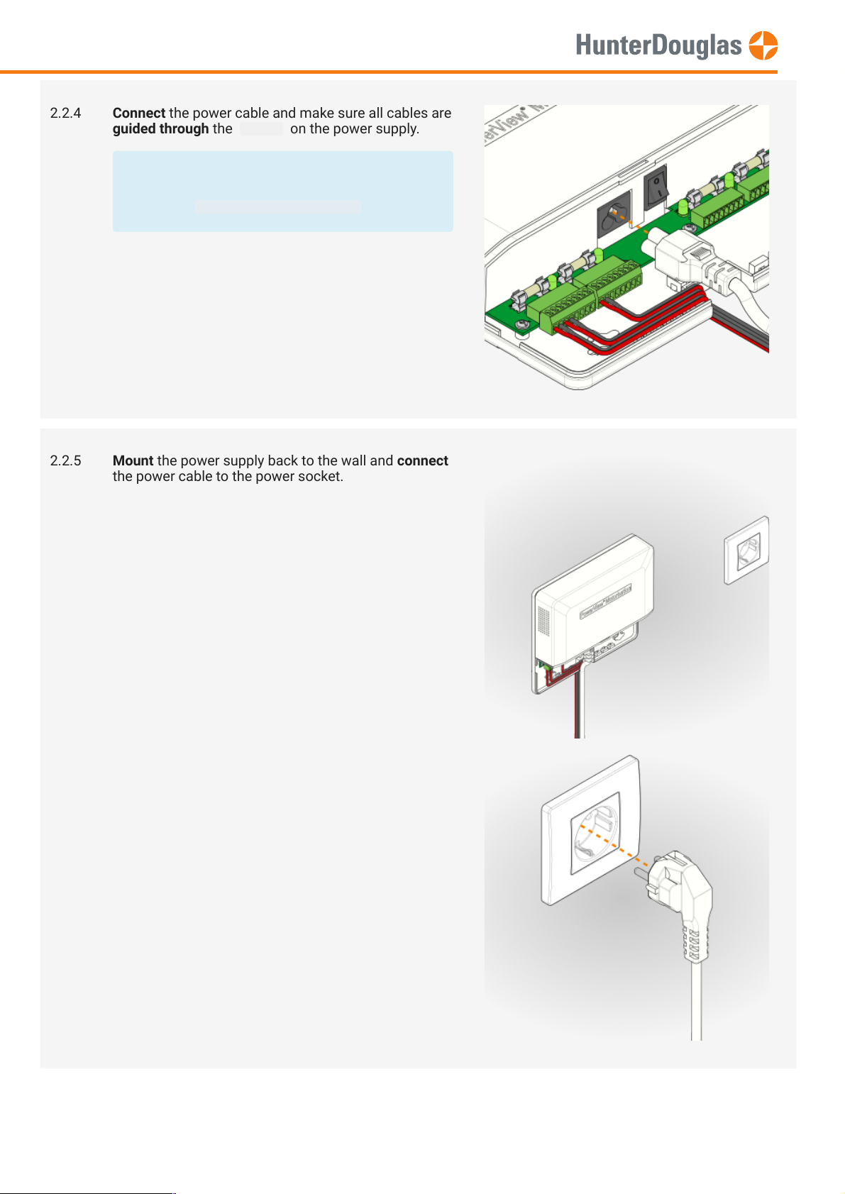
2.2.4 Connect the power cable and make sure all cables are
guided through the recess on the power supply.
TIP.
Use cable ties to fasten all cables and wires
using the cable management clamps .
2.2.5 Mount the power supply back to the wall and connect
the power cable to the power socket.
Page 9 of 13 version: 1.0
Page 10

MANUAL
2.2.6 Flip the power switch to the ON position.
Check if all group LEDs are lit.
2.2.7 Install the front cover.
Check if all PowerView® blinds connected to the
power supply can be controlled up and down .
2.2.8 You are ready to use your PowerView® PS-18/300 power supply.
Page 10 of 13 version: 1.0
Page 11

MANUAL
3. Technical data
Rated input voltage (VAC) 100-240
Rated input Frequency (Hz) 47-63
Rated output voltage (VDC) 18 ± 5%
Eciency level > 90% at full load
No load power (W) < 6
Max. total current output (A) 16
Max. group current output (A) 4.0
Max. power output (W) 288
Output protection (per group) fuse T6.3A/250V
Output holdup time (ms) 8.3
Page 11 of 13 version: 1.0
Page 12

MANUAL
Operation temp. (°C) -40…+50
Operation humidity (%) 20…85
Storage temp. (°C) -40…+80
Storage humidity (%) 10…95
Operational lifetime (hrs) > 100,000 @ 25°C
Material Plastic ABS
Colour white
Dimensions (l x w x h, mm) 223 x 195 x 51
Weight (kg) 0.98
Approvals CE
Page 12 of 13 version: 1.0
Page 13

its products and services, and to discontinue any product or service. Buyers should obtain the latest relevant information before placing orders and
should verify that such information is current and complete. All products (also referred to herein as "components") are sold subject to Hunter Douglas’
terms and conditions of sale supplied at the time of order acknowledgment. Hunter Douglas warrants performance of its components to the
specications applicable at the time of sale, in accordance with its standard warranty terms. Testing and other quality control techniques are used to the
extent Hunter Douglas deems necessary to support this warranty. Except where mandated by applicable law, testing of all parameters of each
component is not necessarily performed. Hunter Douglas assumes no liability for applications assistance or the design of Buyers' products. Buyers are
responsible for their products, applications and interfaces using Hunter Douglas components. To minimize the risks associated with Buyers' products
and applications, Buyers should provide adequate design and operating safeguards. Hunter Douglas does not warrant or represent that any license,
either express or implied, is granted under any patent right, copyright, mask work right, or other intellectual property right relating to any combination,
machine, or process in which Hunter Douglas components or services are used. Information published by Hunter Douglas regarding third-party products
or services does not constitute a license to use such products or services or a warranty or endorsement thereof. Use of such information may require a
license from a third party under the patents or other intellectual property of the third party, or a license from Hunter Douglas under the patents or other
intellectual property of Hunter Douglas. Reproduction of Hunter Douglas information in Hunter Douglas data sheets is permissible only if reproduction is
without alteration and is accompanied by all associated warranties, conditions, limitations, and notices. Hunter Douglas is not responsible or liable for
any altered documentation. Information of third parties may be subject to additional restrictions. Resale of Hunter Douglas components or services with
statements different from or beyond the parameters stated by Hunter Douglas for that component or service voids all express and any implied
warranties for the associated Hunter Douglas component or service and is an unfair and deceptive business practice. Hunter Douglas is not responsible
or liable for any such statements. Buyers acknowledge and agree that they are solely responsible for compliance with all legal, regulatory and safety-
related requirements concerning its products, and any use of Hunter Douglas components in its applications, notwithstanding any applications-related
information or support that may be provided by Hunter Douglas. Buyers represent and agree that they have all the necessary expertise to create and
implement safeguards which anticipate dangerous consequences of failures, monitor failures and their consequences, lessen the likelihood of failures
that might cause harm and take appropriate remedial actions. Buyers fully indemnify Hunter Douglas and its representatives against any damages
arising out of the use of any Hunter Douglas components in safety-critical applications.
MANUAL
Important notice
Page 13 of 13 version: 1.0
 Loading...