

Page 1
Installation • Operation • Care
PowerTilt
™
with
Platinum
™
Technology
Wood, Alternative Wood and Aluminum Horizontal Blinds
Page 2

CONTENTS
Questions?
Call the Hunter Douglas Customer Information Center at
1-888-501-8364
© 2010 Hunter Douglas. ®Registered trademark of Hunter Douglas. ™ Trademark of Hunter Douglas.
The GREENGUARD INDOOR AIR QUALITY CERTIFIED mark is a registered certification
mark used under license through the GREENGUARD Environmental Institute.
Getting Started:
Mounting Types and Window Terminology ....................... 1
Installation Components Needed .................................... 1
Tools and Fasteners Needed .......................................... 2
Product View ................................................................ 3
Installation:
Attach Spacer Blocks (21/2" and 25/8" Slat Sizes)............. 4
Mount the End Brackets – Inside or Ceiling Mount .......... 4
Mount the End Brackets – Outside Mount ....................... 6
Install the Blind ............................................................. 7
Mount the PowerTilt™ Components .............................. 10
Complete the Installation ............................................. 13
Operation:
Raising and Lowering the Blind .................................... 16
PowerTilt™ with Platinum™ Technology Operation ......... 16
General PowerTilt™ Operation ...................................... 17
Troubleshooting .......................................................... 18
Care:
Cleaning Procedures ................................................... 20
Child Safety:
Warning ..................................................................... 21
Radio Frequency FCC Compliance:
This device complies with Part 15 of the FCC Rules. Operation is subject to the following two conditions:
(1) This device may not cause harmful interference, and
(2) This device must accept any interference received, including interference that may cause undesired
operation.
This equipment has been tested and found to comply with the limits for a Class B digital device, pursuant
to Part 15 of the FCC Rules. These limits are designed to provide reasonable protection against harmful
interference in a residential installation. This equipment generates, uses and can radiate radio frequency
energy and, if not installed and used in accordance with the instructions, may cause harmful interference
to radio communications. However, there is no guarantee that interference will not occur in a particular
installation. If this equipment does cause harmful interference to radio or television reception, which
can be determined by turning the equipment off and on, the user is encouraged to try to correct the
interference by one or more of the following measures:
Reorient or relocate the receiving antenna. ■
Increase the separation between the equipment and receiver. ■
Connect the equipment into an outlet on a circuit different from that to which the receiver is ■
connected.
Consult the dealer or an experienced radio/TV technician for help. ■
Any changes or modifications not expressly approved by the party responsible
for compliance could void the user’s authority to operate the equipment.
Page 3
GETTING STARTED
1
Thank you for purchasing this Hunter Douglas product. With proper installation, operation and
care, your new blinds will provide years of beauty and performance. Please thoroughly review
this instruction booklet before beginning the installation.
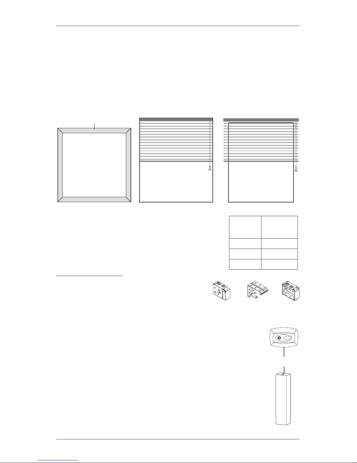
Mounting Types and Window Terminology
If the installation brackets are mounted correctly, the rest of the installation process follows
very easily. To prepare for this important first step, review the mounting types and basic window
terminology illustrated below.
Installation Components Needed
Check the packaging to be sure you have all the components
needed to install your blinds. Keep the packaging until the blinds
perform to your satisfaction.
Required Components
Installation Brackets. ■ Your blinds will come with
two end brackets. Depending on the blind width (see
table above right), intermediate brackets may also be
included.
■ Platinum™ Satellite Eye. Standard wire length is 20". Alternate wire
lengths of 4' or 8' allow the satellite eye to be mounted in a convenient
location where the remote signal may be received without obstructions or
interference from bright, direct light.
Satellite Battery Pack. ■ Standard wire length is 15". Alternate wire lengths
of 4' or 8' allow the battery pack to be mounted in a convenient location that
offers easy access to change the batteries.
Outside Mount
Blind mounts outside
window opening.
Collectively, the sill and
jambs are called the
“window casement.”
Molding
Head Jamb
Sill
Jamb Jamb
Inside Mount
Blind fits within
window opening.
Width of
Blind
Intermediate
Brackets
Required
Up to 48" 0
48
1
/8"-60" 1
601/8"-96" 2
Intermediate
Support
Bracket
End
Bracket
End
Bracket
Alternate
Wire Lengths:
4'
8'
Page 4

2
GETTING STARTED
Optional Components
See illustrations of these optional components on the following page.
Spacer Blocks. ■ Each spacer projects the installation bracket 3∕8" away from the mounting
surface. One spacer block per bracket is required for 21∕2" and 25∕8" slat sizes, and are
optional for the 2" slat size. Spacer blocks are not needed if extension brackets are
being used. Up to three spacer blocks may be stacked.
Extension Brackets. ■ Extension brackets can add up to 31∕2" of clearance for outside
mounts. If ordered, there should be one extension bracket for each installation bracket.
DC Power Supply. ■ This option eliminates the need for batteries. Wire lengths of 12', 16'
or 25' allow the DC power supply to reach the wall outlet nearest the blind or in the least
obtrusive location.
Remote Control. ■ Available as a replacement should the remote that is included with your
order is lost or if an additional remote is desired for blinds in different rooms.
Wireless Wall Switch. ■ Allows you to control your blinds from a central location. The
wireless wall switch works like the remote control.
Connection Interface. ■ Allows PowerTilt™ blinds to be integrated into a home automation
or lighting system.
Hold-Down Brackets. ■ Hold-down brackets secure the bottom rail to prevent the blind from
swaying, yet still allow the slats to tilt.
Bracket Shims. ■ Bracket shims may be used whenever mounting surface is uneven in order
to mount the blind level. Shims are also used to gain clearance for attaching valance clips.
Tools and Fasteners Needed
Flat blade and Phillips screwdriver ■ Level ■
Measuring tape and pencil ■ Needlenose pliers ■
Power drill and drill bits ■
(1∕4" hex driver also recommended)
In addition, you will need fasteners designed to work with your specific mounting surface(s).
#6 Hex Head Screws (Provided). ■ Two 11∕2" screws are provided per installation bracket.
Wall Anchors (Not Provided). ■ If mounting into drywall, you will need wall anchors to
ensure a secure installation.
#6 x 1½"
Hex Head Screw
(Provided)
Wall Anchor
(Not Provided)
Page 5
GETTING STARTED
3
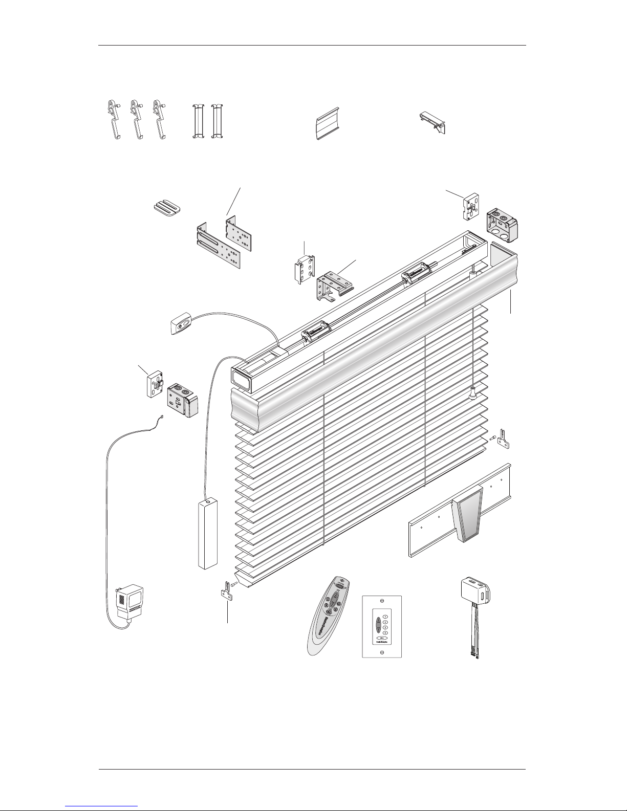
Product View
Valance Clips
Corner Clips for
Valance Returns
(If Required)
Decorative
Keystone
2
End
Bracket
End
Bracket
Valance
Hold-Down
Bracket and Pin
(Optional)
Intermediate
Bracket
(If Required)
1
Required with 21/2", 25/8" slat sizes; optional with 2" slat size
2
Country Woods® wood blinds only; required if valance is over 96", optional if under 96"
3
Country Woods wood blinds only; required for valances with dust covers
Valance Splice
(If Required)
Platinum
Remote
Control
Platinum
Wireless
Wall Switch
Connection
Interface
DC Power
Supply
(Optional)
Satellite
Battery
Pack
Platinum
™
Satellite
Eye
Cornice
Clip
3
End Bracket
Spacer Block
1
End Bracket
Spacer
Block
1
Intermediate
Bracket
Spacer Block
1
Bracket
Shim
2" or 4" Extension
Brackets (Optional)
Page 6
INSTALLATION
4
Attach Spacer Blocks (21/2" and 25/8" Slat Sizes)
Spacer blocks are optional for 2" slat sizes.
Attach a spacer block to each of the two end ■
brackets.
If one or more intermediate brackets is required, ■
attach a spacer block to each intermediate bracket.
If extension brackets will be used, do ■ not use
spacer blocks.
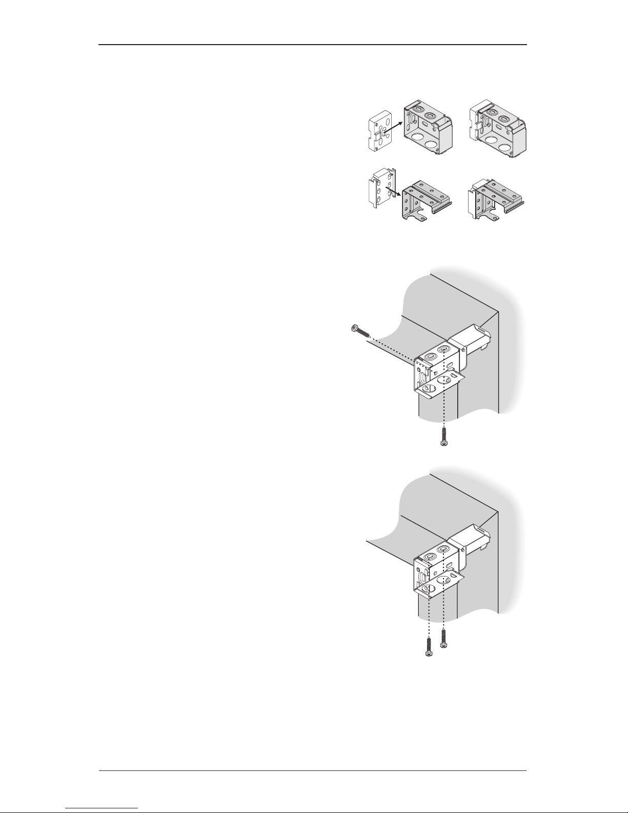
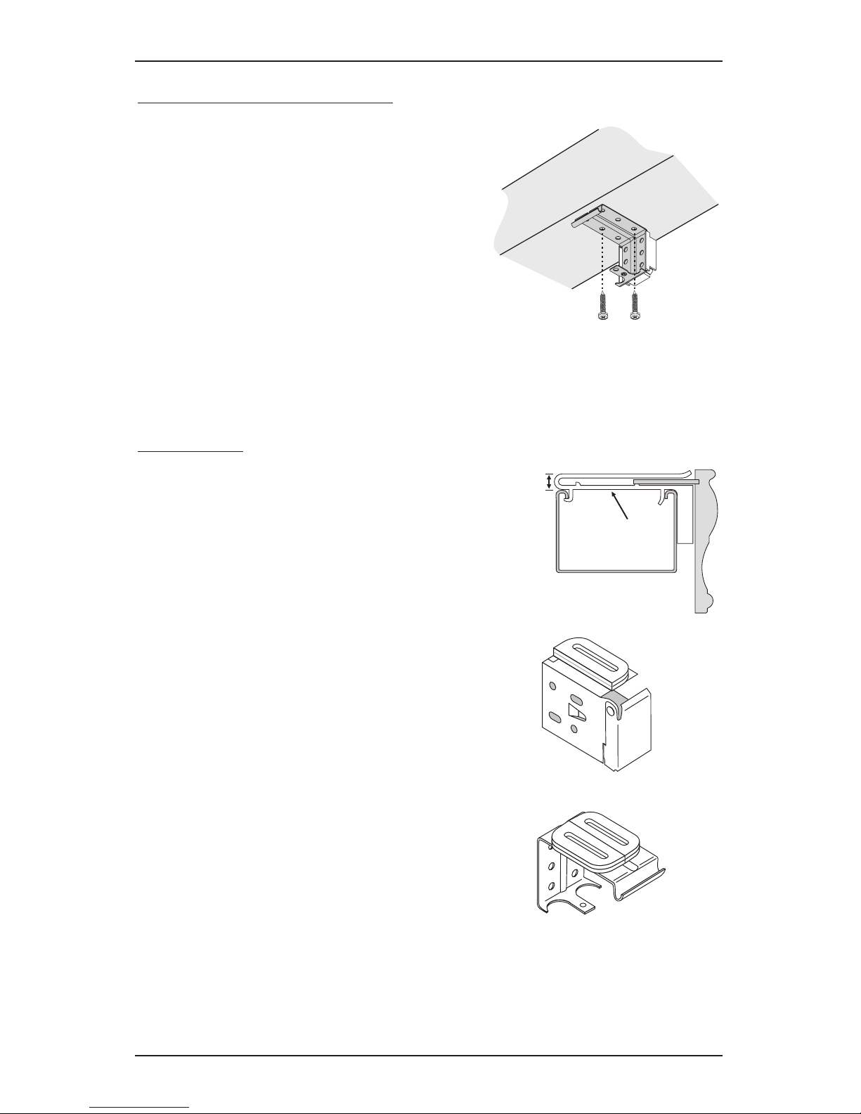
Mount the End Brackets – Inside or Ceiling Mount
With inside mounts or ceiling mounts, attach the two
end brackets flush against the sides of the window
casement or the ceiling. Use a 3∕32" drill bit to drill
holes for the mounting screws. Choose the most
appropriate of the following four mounting methods:
Side mount the brackets with one screw ■
through a side hole and one screw through
a top hole, as shown.
If the brackets are flush with the back wall, ■
attach them with one screw through a top
hole and one through a rear hole.
Top mount the brackets with screws ■
through the two top holes.
If limited mounting depth is available, the bracket ■
may be mounted with two screws through
diagonal side holes.
Important: For blinds with 2
1
/
2
" or 2
5
/
8
"
slats, spacer blocks are used with inside mounts
to position the brackets a minimum of
3
/
8
" from
the glass. This prevents slats from rubbing the
glass when tilting or when the blind is raised and
lowered.
Important: Spacer blocks are optional for 2" slat sizes.
End Bracket
Intermediate Bracket
Side
Mount
Top
Mount
Top
Mount
Page 7
INSTALLATION
5
Intermediate Brackets (If Required)
Evenly space the intermediate bracket(s) between the
two end brackets.
CautIon: Intermediate bracket placement may be
adjusted to avoid interference with working parts in
the headrail.
Attach with two screws through diagonal holes. ■
The backs of the end brackets and intermediate ■
bracket(s) must align.
Important: With ceiling mounts, you may need to add a bracket shim to allow clearance
for the valance clips.
Bracket Shims
In addition to being used to gain clearance for valance clips
with ceiling mounts, bracket shims are needed to add top
clearance when a valance with optional dust cover is used
and the blind is inside mounted, but the headrail is not fully
recessed. (If the headrail is fully recessed or ceiling mounted,
the optional dust cover would not be ordered.)
An additional 3/8" of clearance is needed to accommodate
the height of the cornice clips, as shown in the illustration.
To gain this clearance, use the bracket shims included
with your order (one for each end bracket and two for each
intermediate bracket).
With each installation bracket, first fold the shim ■
and then position it on top of the bracket to gain
the required clearance.
With each intermediate bracket, stack two ■
unfolded shims.
Important: Bracket shims may also be used whenever
the mounting surface is uneven in order to mount the
blind level.
3
⁄8" Clearance
Cornice
Clip
One Shim
Folded Over
Two Shims
Stacked
Installation Bracket
Intermediate Bracket
Page 8
INSTALLATION
6
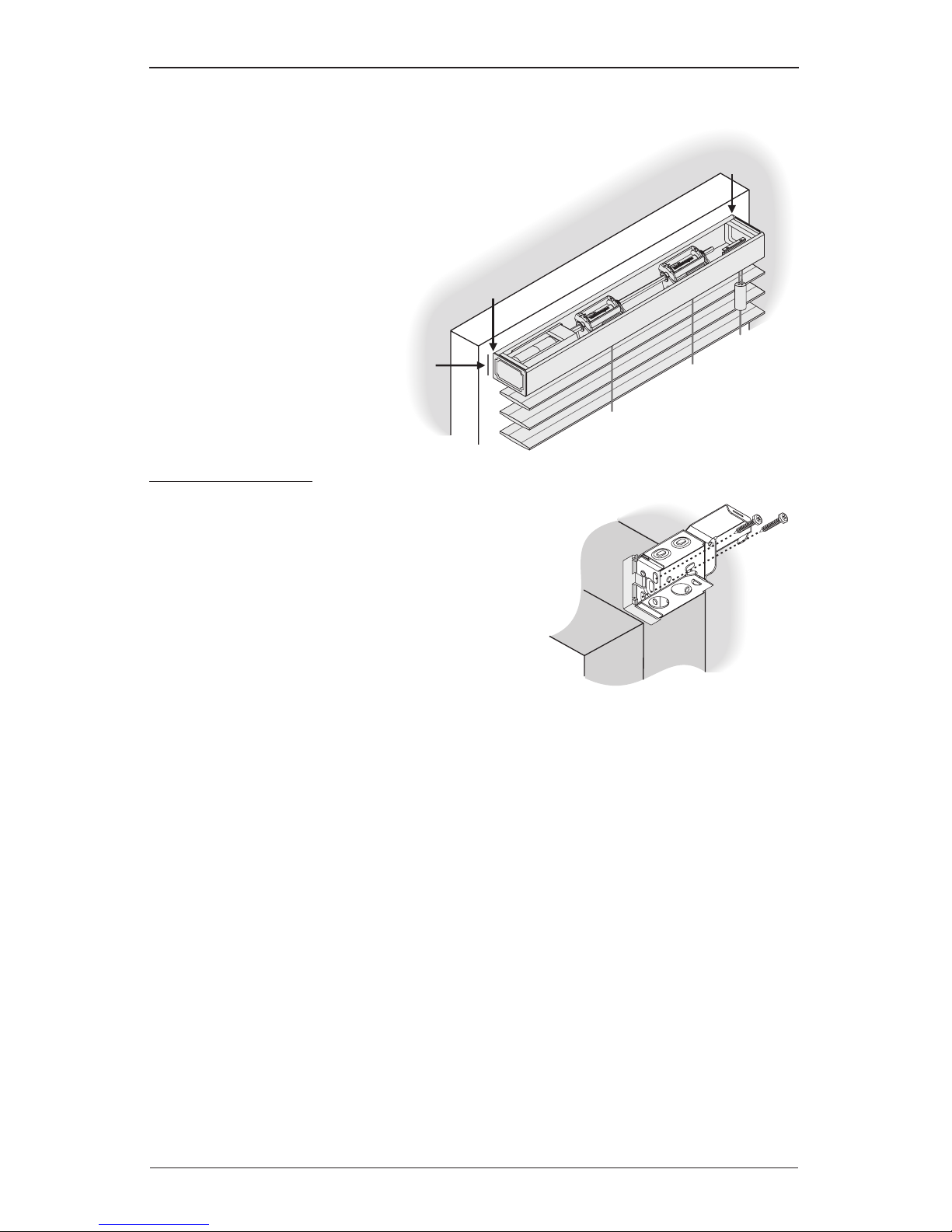
Mount the End Brackets – Outside Mount
A flat vertical surface at least 1
3
/
4
" high is required for bracket
attachment.
Mark where the ends of the headrail will ■
be located.
Either hold the headrail up to the ■
mounting surface or measure
the headrail and mark its
width.
Then mark ¼" to ■
the outside of the
headrail end marks.
Attach End Brackets
Align the outside edge of each bracket with the ■
outer marks.
The tops of the brackets must be aligned at the ■
same height.
Mark the location of the holes for the screws. ■
The brackets will be attached with two screws ➤
through diagonal rear holes.
Using a ■
3
∕32" drill bit, drill holes for the mounting screws.
Important: If you are fastening the end brackets to drywall, be sure to use wall anchors
and follow the instructions provided with the anchors. (Anchors not provided.)
Use a level to check that the mounting surface is level. Shim the brackets if necessary. ■
Use the hex head screws provided with your order to fasten the installation brackets to the ■
mounting surface.
Important: The front edges of the installation brackets must align to each other.
Mark
Mark
Measure and mark
¼" out from
ends of headrail.
Page 9

INSTALLATION
7
Intermediate Brackets (If Required)
Evenly space the intermediate bracket(s) between the
end brackets.
CautIon: Intermediate bracket placement may be adjusted to
avoid interference with working parts in the headrail.
The top of each intermediate bracket must align with ■
the tops of the end brackets.
Attach the bracket(s) with two screws through diagonal holes. ■
Extension Brackets (Optional)
Attach 2" or 4" extension brackets to the mounting surface in the same locations where the end
brackets and intermediate brackets would be attached.
Align and level extension brackets with a carpenter’s level. ■
Use two screws to mount each extension bracket. ■
Attach the installation brackets and intermediate brackets to the extension brackets using ■
the screws and nuts provided, as shown below.
Install the Blind
Check Connections to the Motor Housing
Satellite Battery Pack or Optional DC Power Supply
From the top of the headrail, check that the 2-wire connector from the satellite battery pack ■
or optional DC power supply is securely inserted into the 2-port plug on the motor housing.
If the connection is loose, make sure the orientation of the plug is correct before attempting
to make the connection. Do not force the connection. Needlenose pliers may be helpful in
making the connection, if necessary.
End Bracket with
2" Extension Bracket
Intermediate Bracket
with 2" Extension Bracket
End and Intermediate Brackets
with 4" Extension Bracket
Page 10

INSTALLATION
8
Platinum™ Satellite Eye
From the top of the headrail, check that the 6-wire connector from the satellite eye is ■
securely inserted into the 6-port plug on the motor housing. If the connection is loose, make
sure the orientation of the plug is correct before attempting to make the connection.
Do not force the connection. Needlenose pliers may be helpful in making the connection, if
necessary.
Valance Clips
Attach valance clips to the ■
headrail, as shown.
Evenly space the valance clips ■
along the length of the headrail,
no more than 36" apart.
Do ■ not place the valance clips
where they could interfere with
any working parts.
If desired, the valance may be positioned ¼" higher by raising the clips one notch up, ■
as shown in the illustration above.
Cornice Clips — Wood Blinds Only
Cornice clips are used instead of valance clips when the valance has a dust cover.
Attach a cornice clip 2" from each end of the headrail. ■
Space additional clip(s) evenly between the two end clips so that the cornice clips are no ■
more than 36" apart.
Do ■ not place the cornice clips where they could interfere with any working parts.
Two-Port
Power Plug
Outer End of Motor Housing
Tiltrod Side of Motor Housing
Six-Port
Satellite Eye
Plug
Tiltrod
Inserted
Here
Standard
Position
Raised Clip for a
Higher Valance
Front of Headrail
No More Than 36"2" 2"No More Than 36"
Page 11

INSTALLATION
9
If a valance with dust cover also has one or more keystones, do not mount cornice clips ■
where they would interfere with the keystone dust cover(s). Rather, mount them so that they
will be located on each side of the keystone dust cover(s), as shown below.
To attach the cornice clips, hook the back of the clip to ■
the rear lip of the headrail.
Push the clip down until it snaps securely in place. ■
Mount the Headrail
Important: If installing the satellite battery pack inside the headrail see page 11, Mounting
the Satellite Battery Pack Inside the Headrail, before mounting the headrail.
Tilt headrail so that its back lip slides under the front lip of the end brackets and ■
intermediate bracket(s).
Push headrail against the back of the end brackets. ■
Check that the front lip of the intermediate bracket(s) is under the front lip of ■
the headrail.
Be sure to keep the satellite eye outside of the headrail. ■
Valance
Dust Cover
Keystone
Dust Cover
Cornice Clip
Front of
Headrail
End Bracket
Intermediate Bracket
Page 12

INSTALLATION
10
Adjust Headrail Tightness
If the headrail is loose in the end brackets, bend the tabs on ■
the end brackets outward.
Important: The tabs may also be bent inward if the
headrail is difficult to install into the end brackets.
If your headrail end brackets do not have adjustable tabs, ■
bend the tabs on the headrail end locks to adjust headrail
tightness.
Close End Brackets
Push the cover down until it snaps over the locking tab on ■
the bottom of the bracket.
Open End Brackets
To open the end brackets, insert a flathead screwdriver ■
between the bottom of the cover and the quick release tab,
and twist.
You can also push up on the bottom of the bracket to ■
release the locking tab.
Mount the PowerTilt™ Components
After the blind is installed, mount the PowerTilt components.
Satellite Battery Pack
Determine where to mount the satellite battery pack.
If mounting the satellite battery pack outside the headrail, install the blind first. ■
If mounting the satellite battery pack inside the headrail, install the battery pack before ■
installing the blind, see page 11.
notes: With the battery pack inside the headrail, the blind must be removed from the
window to change batteries (battery life is approximately two years, depending on usage).
The battery pack must be mounted outside the headrail on alternative wood blinds
with cable tapes between 30" - 33" wide and between 30" - 35" wide on wide-tape blinds.
Page 13

INSTALLATION
11
Mounting the Satellite Battery Pack
Outside the Headrail
Mount the battery pack in a location where it will
not interfere with the operation of the blind.
Outside Mounts. ■ Route the wire so it exits from
the top of the blind.
Inside Mounts. ■ Route the wire so it runs along
the motor side end bracket to the front of the blind.
Install the satellite battery pack housing. ■
Remove the cover of the battery pack by pressing ➤
on the circular latch and lifting the cover off.
Use the holes in the rear of the housing as a ➤
template to mark the screw locations on the
mounting surface.
Attach using two screws (included). ➤
Load batteries into the satellite battery pack. ■
Install eight AA alkaline batteries according to the ➤
instructions on the battery pack.
Replace the cover, snapping it securely closed. ➤
tIp: The satellite battery pack cover may be painted to
match the wall color.
Mounting the Satellite Battery Pack
Inside the Headrail
Load batteries into the satellite battery pack (see instructions above). ■
Mount the battery pack inside the headrail in a location where it will not interfere with the ■
operation of the blind. Position its smooth, curved side toward the tiltrod.
Carefully tuck excess wire into the headrail. Be sure to avoid any moving parts. ■
Inside Mount Blind
Outside Mount Blind
Loading Batteries
Tiltrod
Satellite Battery Pack
Back of Headrail – Overhead View
Motor Housing
To Satellite
Eye
Page 14

INSTALLATION
12
Platinum™ Satellite Eye
Determine where to mount the satellite eye.
Choose a location for the satellite eye where the infrared ■
(IR) signal from the remote control is not obstructed. Do
not mount the satellite eye in direct sunlight or bright,
focused light from halogen or fluorescent light fixtures,
track lighting, spotlights, or neon lights.
Check that the wire is not caught or pinched in the ■
brackets or headrail.
With inside mounts, route the wire behind the headrail and ■
along the motor side end bracket to the front of the blind.
Mount the Platinum Satellite Eye
Flip the satellite eye down and place the hinged flange ■
against the wall. Attach the flange to the wall with a single
screw or double-sided tape.
Flip the satellite eye back up to the correct position for ■
receiving the signal from the remote control.
note: For radio frequency (RF) operation, the satellite eye does not need to be visible. After
the blind has been programmed for RF operation, the satellite eye can be placed inside the
headrail or covered by a drapery or top treatment. See the Platinum™ Technology Remote
Control Guide or Platinum Technology Wireless Wall Switch Guide for programming details.
Optional DC Power Supply
The DC power supply plugs into a standard outlet.
Route the wire to a location where it will not interfere with ■
the blind.
Outside Mounts. ➤ Route the wire so it exits from the top of
the blind.
Inside Mounts. ➤ Route the wire so it runs along the motor
side end bracket to the front of the blind.
Plug the DC power supply into a standard outlet. ■
Outside Mount Blind
Inside Mount Blind
Wall
Hinged
Flange
Page 15

INSTALLATION
13
Complete the Installation
Attach the Valance Returns (If Necessary)
If the valance came with returns and they are not already
attached, connect the returns to the valance using the
corner clips provided.
The notches on the rear of the valance and returns ■
fit into the grooves of the corner clips.
Slide one end of each clip onto the rear of the ■
valance until the center of the clip aligns with the
edge of the miter cut at each end.
Slide a return onto each corner clip until its miter is ■
flush against the miter on the valance.
Splice Valances
For valances that are spliced and did not come with a
decorative keystone, adjoin the two mitered valance
pieces together by sliding the valance splice clip onto the
back of the valance where the two halves meet.
Decorative Keystone
Wood Blinds Only
If a decorative keystone was ordered, splice
it to the two angled valance pieces.
Firmly press the two pieces together. ■
Anchor them in position using the provided
set screws. Secure the screws into the
back of the valance through the holes in
the keystone.
Repeat the procedure for the other angle. ■
Miters Meet
Corner
Clip
Valance
Valance
Return
(Cross-
Section)
Notch
Notch
Valance
Splice Clip
Miters
Angle Cut Valance Pieces
Keystone
Set Screw
Page 16

INSTALLATION
14
Attach the Valance (Without Dust Cover)
Wood Blinds and Alternative Wood Blinds
Tilt the valance to insert its bottom notch into the bottom part of the valance clip. ■
Pulling the valance slightly downward, insert the top notch of the valance into the clip, ■
as shown.
To remove the valance, gently pull the valance downward to release it from the top ■
of the valance clips. Rotate the top of the valance toward you. Lift up the valance to release
it from the bottom of the valance clips.
Aluminum Blinds
Tilt the valance to insert its bottom notch into the bottom part of the valance clip. ■
Pulling the valance slightly downward, insert the top notch of the valance into the clip, ■
as shown.
To remove the valance, pull down on the valance and pull out. ■
Attach the Valance (With Dust Cover)
Wood Blinds Only
Slide the valance dust cover onto the ■
cornice clips, as shown in the illustration.
Secure the dust cover with a ¼" wood ■
screw through the slot in the cornice clip.
Bottom Notch
Top Notch
Bottom Notch
Top Notch
Valance
Dust Cover
Cornice Clip
Secure with ¼"
Wood Screw
Page 17

INSTALLATION
15
Notch the Dust Cover (21/2" and 25/8" Blinds)
Wood Blinds Only
When spacer blocks are used to provide clearance for 21/2" and
25/8" slats, the valance dust cover must be notched to allow
the valance returns to be flush against the wall.
Mark the location of the cornice clips on the ■
dust cover.
Use a utility knife to notch the rear of the dust ■
cover where the dust cover will fit onto the
cornice clips.
The notch should be ½" deep and ¾" wide, ■
as shown at right.
Attach the Hold-Down Brackets (Optional)
Drill a ■
3
/32" hole centered in the ends of the bottom rail for wood and alternative wood blinds.
For aluminum blinds, push out the perforated pin plug from each bottom rail end cap using
a ballpoint pen or similar pointed object.
Insert a hold-down pin into each hole. Push the head of the pin against a flat surface to fully ■
seat it, or tap the pin in place with a hammer.
To mount the hold-down brackets, first fully lower the blind. Align the first or second slot on ■
the brackets with the pin heads in the bottom rail.
Align the first slot with 2 ➤
1
/2" and 25/8" slat sizes.
Align the second slot with 2" slat sizes. ➤
Maintain the correct slot alignment as you attach the hold-down brackets to the jamb, sill or ■
outside mounting surface.
Slide the hold-down pins into the second slot with 2" slat sizes. Slide the hold-down pins ■
into the first slot with 21/2" and 25/8" slat sizes.
With 2" slat sizes, the first slot may be used instead of a spacer block. ■
1
/
2
"
3
/
4
"
Jamb
Mount
Second
Slot
First Slot
Sill
Mount
Outside Mount
Page 18

OPERATION
16
Raising and Lowering the Blind
Important: Whenever raising or lowering the blind, the slats
must be in the open position.
Pull the single cord down and toward the ■
center to raise and lower.
Hold the cord to the outside to ■
lock the blind in position.
PowerTilt™ with Platinum™ Technology Operation
Infrared (IR) “Point and Press” Operation. ■ With IR operation, a focused infrared beam
from the remote control provides the signal to tilt the slats. IR is a line of sight technology;
the beam must be continuous from the remote control to the satellite eye.
Radio Frequency (RF) “Group Mode” Operation. ■ With RF operation, radio frequencies
are used to provide the signal to tilt the slats. RF can be used to control a selected group of
blinds that are either in view or out of view.
Platinum™ Technology Remote Operation
For information regarding operation and programming of the
Platinum™ Technology remote control, refer to your Platinum
Technology Remote Control Guide.
Platinum Technology Wireless Wall Switch Operation
For information regarding operation and programming of
the Platinum Technology wireless wall switch, refer to your
Platinum Technology Wireless Wall Switch Guide.
Home Automation Control Using the Connection Interface
For information about integrating PowerTilt™ operation with a home automation or lighting
system, refer to the Connection Interface Installation Guide.
Pull Cord
Toward Outside
to Lock
Pull Cord
Toward Center to
Raise and Lower
Raising and
Lowering
Page 19

OPERATION
17
General PowerTilt™ Operation
Using the Manual Control Button
In addition to the remote control and wireless wall switch,
the manual control button on the satellite eye can also be
used to tilt the slats.
Press the manual control button to tilt the slats. The ■
slats will move for as long as the button is pressed.
Release and press the button a second time to tilt the ■
slats in the opposite direction.
Changing the Batteries
Changing the Batteries in the Satellite Battery Pack
Remove the cover of the battery pack by pressing the ■
circular latch and lifting the cover.
Remove the eight old AA batteries. ■
Install eight new AA alkaline batteries according to the ■
instructions on the battery pack.
Replace the cover, snapping it securely closed. ■
Changing the Batteries in the Remote Control
Remove the back center panel of the remote control by pushing down on the latch and ■
pulling it out.
Remove the two old AAA batteries. ■
Install two new AAA alkaline batteries as shown inside the remote control. ■
Replace the back cover panel. ■
Important Notes about Battery Usage
Alkaline batteries are strongly recommended; do ■ not use rechargeable batteries.
Manual Control Button
Changing Batteries
Page 20

OPERATION
18
Channel
Selector
Switch
UP /DOWN
Buttons
Troubleshooting
If your blind is not operating correctly, first review the guide that came with your Platinum™
remote or wireless wall switch; then, if necessary, refer to the procedures below.
Problem Solution
The blind does not operate
using either the remote
control or the manual
control button.
Check that the battery pack (or optional DC power supply) ■
and satellite eye are securely connected into their motor
housing plugs. See page 7, Check Connections to the
Motor Housing.
Check that the batteries in the battery pack are installed ■
correctly and fresh. See page 17, Changing the Batteries
in the Satellite Battery Pack.
Check that the DC power supply, if used, is securely plugged ■
into the wall outlet and the outlet has power. To check outlet
power, plug in a lamp or device that is known to work.
The blind operates using
the manual control button,
but does not operate
using the remote control
in the IR (line of sight)
operating mode.
If the light on the remote ■
does not light up when
the UP ▲ or DOWN ▼
button is pressed, replace
the batteries in the remote.
Check that the correct channel is selected on the remote ■
control. Try both channels.
Check that you are pointing the remote control directly at ■
the infrared eye. Try moving closer to the eye. Maximum
operating distance from the remote control is 30 feet.
Check that there are no obstructions interfering with the ■
signal from the remote to the satellite eye.
Check that there is no direct sunlight or bright, focused ■
light from halogen or fluorescent light fixtures, track
lighting, spotlights, or neon lights that could be interfering
with the signal.
The blind does not hang
correctly.
Check that the installation brackets are level. ■
The lift cords are stuck or
jammed.
Check the cords and the moveable pin in the cordlock ■
mechanism inside the headrail. If the cords are jammed,
use a screwdriver or needlenose pliers to move the pin to
free the cords.
Page 21

OPERATION
19
Problem Solution
The blind operates using
the manual control button
but does not operate
using the remote control
in the RF (group) operating
mode.
Be sure the blind operates properly in the infrared mode. ■
The Group feature will not work correctly if the infrared
mode does not work correctly.
Be sure the blinds have been correctly programmed ■
to the remote control you are using. If your remote
control has not been set up to operate your blinds, only
the infrared mode will work. See the information about
assigning blinds to a group in the Platinum™ Technology
Remote Control Guide or the Platinum Technology
Wireless Wall Switch Guide.
Blind(s) in a group
are tilting in opposite
directions.
Remove the problem blind(s) from the installation brackets ■
and locate the motor unit at the end of the headrail.
Find the small metal switch on the top of the motor ➤
unit that has a molded "R" and "L" on either side.
Use a small screwdriver, the end of a paper clip, or ➤
similar tool to move the switch to the opposite side.
The motor operates, but
the slats do not tilt.
Check that no obstructions inside the headrail are ■
preventing the tilting mechanism from turning.
Check that the tiltrod is completely snapped into the motor. ■
The slats do not tilt
completely.
Check for obstruction that may be interfering with slat ■
movement.
Motor operation is slowing;
slats tilt slower than before.
Replace the batteries in the satellite battery pack. ■ See page
17, Changing the Batteries in the Satellite Battery Pack.
It is difficult to reach the
satellite battery pack to
change the batteries.
Satellite battery packs with wire lengths up to 8' are ■
available. See page 1 for size availability.
The remote control is lost. Contact your dealer for a replacement remote control. ■
Use the manual control button until the remote control is ■
received. See page 17, Using the Manual Control Button.
Switch
Top View
Motor
Unit
Page 22

CARE
20
Cleaning Procedures
Like any fine furnishings, Hunter Douglas wood, alternative wood and aluminum blinds should be
cleaned regularly to keep them looking new.
Wood, Alternative Wood and Aluminum Blinds
Dust regularly. Use a soft clean cloth, chemically-treated dust cloth or dusting mitt. Lower ■
the blind to its full length, tilt the slats almost all the way down and dust. Then tilt the slats
almost all the way up and dust. (Not closing the slats all the way allows dusting where the
slats overlap.)
Blinds may also be vacuumed. Use the brush attachment and tilt the slats up and down as ■
described for dusting.
Another way to clean blinds is simply by wiping them with a soft, damp cloth. ■
Wood Blinds Only
Stained blinds, like wood furniture, should be treated periodically with lemon oil or other ■
wood preservative to protect their finish and enhance their luster.
Alternative Wood and Aluminum Blinds
Wash only the slats using a non-abrasive mild detergent solution. Allow to air dry to preserve ■
the dust repellent properties of the slats.
For a more thorough cleaning, bottom rails and slats may be immersed in a bathtub. Do not ■
immerse headrails or wood bottom rails. Bathtub cleaning is not recommended for blinds
with wide tapes.
Important: Hunter Douglas does not recommend ultrasonic cleaning of wood, alternative
wood or aluminum blinds.
A NOTE ABOUT WOOD PRODUCTS: Our wood blinds are true wood products, made
from 100% wood. There will be variations in color, grain, texture, and warp that are
characteristics of all wood. These variations will be especially visible in blinds with light
color stains. The variations are normal and natural, and are considered acceptable quality.
Page 23

CHILD SAFETY
21
Warning
WARNING
For more safety information call 1-888-501-8364
in the U.S. or 1-866-662-0666 in Canada.
Young children can STRANGLE in cord loops and in the loop
above the cord stop. They can also wrap cords around their
necks and STRANGLE. In addition, inner cords can pull out
to form a loop, which can STRANGLE a young child.
Always keep cords out of children’s reach.
Move cribs, playpens and other furniture away from ■
cords. Children can climb furniture to get to cords.
Do not tie cords together. Make sure cords do not twist together and create a loop. ■
Cord Stop
This component acts as a stopper to prevent inner ■
cords from being pulled through the blind, which can
pose the risk of entanglement.
It is also designed to break apart under significant ■
pressure, which may lessen the risk of entanglement
in the top lift cords.
Reassembly of Cord Stop
Reinsert any loose cords into the top notches of the cord ■
stop. There is a notch on each side.
Line up the two halves of the cord stop and snap the ■
pieces back together.
Cord Cleats
Hunter Douglas offers cord cleats and we recommend their use.
Attach two cord cleats 6" to 12" apart at a height where they will be ■
out of the reach of children. Take into account that a child may stand on
furniture attempting to reach the cords.
Be sure the cleats are firmly secured. ■
Once the cleats are attached, wrap excess cord around them after each ■
use of the blind.
Four
Cords
Two
Cords
Page 24

5130541000 4/10
The Hunter Douglas® Lifetime Guarantee is an expression of our desire to provide a thoroughly satisfying
experience when selecting, purchasing and living with your window fashion products. If you are not thoroughly
satisfied, simply contact Hunter Douglas at (888) 501-8364 or visit hunterdouglas.com. In support of this policy
of consumer satisfaction, we offer our Lifetime Limited Warranty as described below.
NOTE: In no event shall Hunter Douglas or its licensed fabricators/distributors be liable or responsible for incidental
or consequential damages or for any other indirect damage, loss, cost or expense. Some states do not allow the exclusion or
limitation of incidental or consequential damages, so the above exclusion or limitation may not apply to you. This warranty
gives you specific legal rights, and you may also have other rights which vary from state to state.
Different warranty periods and terms apply for commercial products and applications.
Hunter Douglas (or its licensed fabricator/distributor) will repair or replace the
window fashion product or components found to be defective.
COVERED
BY A LIFETIME LIMITED WA RRANTY
• Hunter Douglas window fashion products are
covered for defects in materials, workmanship
or failure to operate for as long as the original
retail purchaser owns the product (unless shorter
periods are provided below).
• All internal mechanisms.
• Components and brackets.
• Fabric delamination.
• Operational cords for a full 7 years from the
date of purchase.
• Repairs and/or replacements will be made with
like or similar parts or products.
• Hunter Douglas motorization components are
covered for 5 years from the date of purchase.
NOT COVERED
BY A LIFETIME LIMITED WA RRANTY
• Any conditions caused by normal wear and tear.
• Abuse, accidents, misuse or alterations to the
product.
• Exposure to the elements (sun damage, wind,
water/moisture) and discoloration or fading
over time.
• Failure to follow our instructions with respect
to measurement, proper installation, cleaning
or maintenance.
• S hipping charges, cost of removal and reinstallation.
TO OBTAIN WA RRANTY SERVICE
1. Contact your original dealer (place of purchase) for warranty assistance.
2. Visit hunterdouglas.com for additional warranty information, frequently asked questions and access to service locations.
3. Contact Hunter Douglas at (888) 501-8364 for technical support, certain parts free of charge, for assistance in obtaining
warranty service or for further explanation of our warranty.
 Loading...