

Page 1
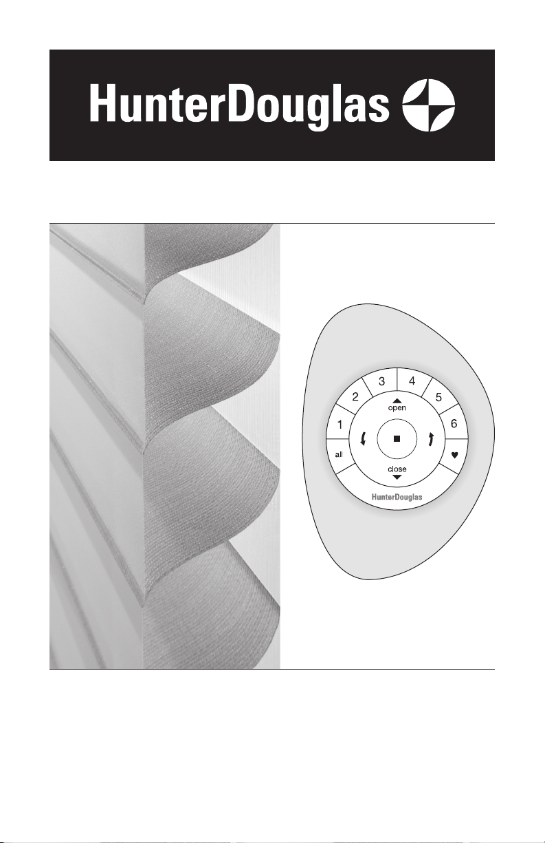
Installation • Operation • Care
Silhouette® and Nantucket™
Window Shadings
PowerView® Motorization
Page 2

CONTENTS
Getting Started:
Product View .................................................................................... 1
Tools and Fasteners Needed .............................................................. 2
Installation:
Installation Overview ......................................................................... 3
STEP 1: Mount the Installation Brackets .............................................3
Inside Mount ................................................................................. 4
Outside Mount .............................................................................. 6
End Mount .................................................................................... 8
STEP 2: Mount the Battery Wand and Connect the Power Cable .......... 9
STEP 3: Install the Shading ............................................................. 10
STEP 4: Connect the Power Source, If Applicable .............................12
Attach Magnetic Hold-Down Brackets (Optional) ................................ 15
Operation:
Testing the Shading ......................................................................... 16
Using the PowerView Remote .......................................................... 16
Resetting the Shading (If Necessary) ................................................ 19
Troubleshooting .............................................................................. 20
Care:
Removing the Shading..................................................................... 25
Cleaning Procedures ....................................................................... 25
Declarations .................................................................................. 27
Warranty ............................................................................ Back Cover
Questions?
Call Hunter Douglas Consumer Support at 1-888-501-8364.
© 2018 Hunter Douglas. All rights reserved. All trademarks used herein are the property of Hunter Douglas or
their respective owners.
Page 3
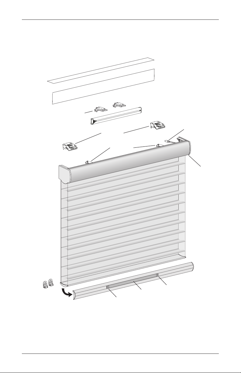
Product View
Programming
Hold-Down
Clip
Optional Dust Cover
Battery Wand Clips
Battery Wand
GETTING STARTED
(For Outside Mount)
Optional Back Cover
(For Inside/End Mount only)
Power Cable
Installation
Brackets
Limit Stops
Button
Magnetic
Brackets
(Optional)
Weight
Bottom Rail
Balance Weight
Weight
Clip
1
Page 4
GETTING STARTED
Thank you for purchasing Hunter Douglas Silhouette® or Nantucket™ Window Shadings with
®
PowerView
Motorization. With proper installation, operation, and care, your new shadings will
provide years of beauty and performance.
Please thoroughly review this instruction booklet and the packing list before beginning the
installation.
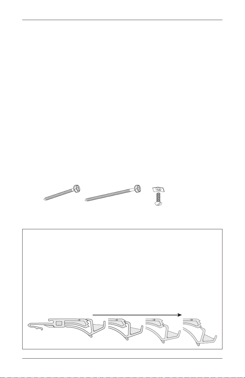
Tools and Fasteners Needed
■ Flat blade and Phillips screwdrivers ■ Level (laser level is recommended)
■ Measuring tape and pencil ■ Pliers or heavy-duty scissors
■ Power drill,
and
In addition, you will need fasteners designed to work with your specific mounting surface(s).
■ #6 Hex Head Screws (Provided). Two 1
■ Longer Hex Head Screws (Not Provided). If using spacer blocks, use #6 screws long
enough for a secure attachment.
■ Speed Nuts and Screws (Provided). Extension brackets come with screws and speed nuts.
■ Drywall Anchors (Not Provided). Use drywall anchors when mounting into drywall.
3
/32" drill bit,
1
/4" hex driver
1
#6 x 1
Hex Head Screw
(Provided)
/2"
1
/2" screws are provided per installation bracket.
Longer #6 Hex Head Screw
for Use with Spacer Blocks
(Not Provided)
Speed Nut
and Screw
(Provided with Each
Extension Bracket)
Importance of Limit Stops on Silhouette and Nantucket Window Shadings
Limit stops serve as the upper travel limit for the bottom rail, preventing it from rotating
around the fabric roll. Limit stops are located 6" from the ends of the headrail or are
centered on shadings less than 36" wide.
When a shading is made, the limit stops are adjusted according to the size of the fabric
roll. Occasionally, this adjustment changes during shipping or installation. If this happens,
problems can be fixed by readjusting the limit stops. See page 21 in the Troubleshooting
section if shading operation is difficult or if the bottom rail rotates around the fabric roll.
Shown below are the four possible positions of limit stops for large to small fabric rolls.
Large Fabric Roll Small Fabric Roll
2
Page 5
INSTALLATION
Installation Bracket For Added Clearance
Bracket
Block
Molding
Installation Overview
To install your shading, you will need to perform the following four steps:
STEP 1: Mount the Installation Brackets
STEP 2: Mount the Battery Wand and Connect the Power Cable
STEP 3: Install the Shading
STEP 4: Connect the Power Source, If Applicable
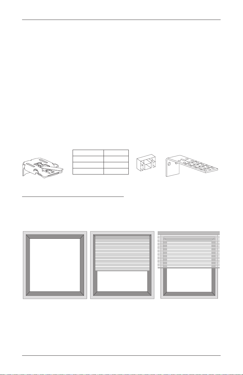
STEP 1: Mount the Installation Brackets
■ Your order will include the correct number of installation brackets for your shading width, as
shown in the table below.
■ Shading orders may also include spacer blocks or extension brackets, if they were specified
for added clearance.
➤ Extension brackets are used for end mount shadings, as well.
Shading Width Brackets
14" to 48"
481/8" to 96"
961/8" to 120"
2
3
4
1
/2" Spacer
Extension
Mounting Types and Window Terminology
If the installation brackets are mounted correctly, the rest of the installation process follows
easily. To prepare for this important first step, review the mounting types and basic window
terminology illustrated below.
Head Jamb
Jamb Jamb
Collectively, the sill and
jambs are called the
“window casement.”
Sill
■ Refer to the appropriate page below based on the mounting type chosen for your order:
Inside Mount
Shading fits within
window opening.
➤ Inside Mount — Page 4
➤ Outside Mount — Page 6
➤ End Mount
— Page 8
Outside Mount
Shading mounts outside
window opening.
3
Page 6
Motor
Jamb Jamb
Back Cover Bracket
battery wand and no back cover.
Bottom
INSTALLATION
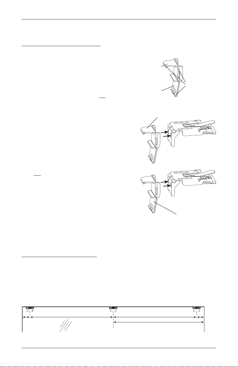
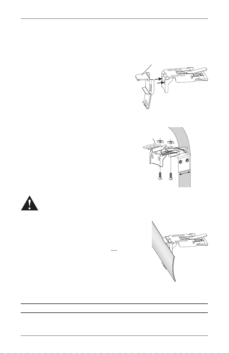
Mount the Installation Brackets — Inside Mount
Prepare the Installation Brackets
The purpose of the back cover bracket is to
provide an attachment for the optional back cover.
The top tab ensures that there is clearance for the
battery wand.
■ If using the optional back cover:
➤ If you have a battery wand, do not remove
the top tab on the back cover bracket.
➤ If you have a satellite battery pack or an
18V DC power supply, remove the top tab
on the back cover bracket.
➤ Snap the back cover bracket into the metal
installation bracket.
➤ Place the back cover into the slots on the
top and bottom of the bracket.
■ If not using the optional back cover:
➤ If you have a battery wand, remove the
bottom tab from the back cover bracket.
➤ Snap the back cover bracket into the metal
installation bracket. This ensures adequate
space for the battery wand.
➤ If you have a satellite battery pack or an
18V DC power supply, it is not necessary
to use the back cover bracket.
Top Tab
Remove top tab if using a satellite
battery pack or an 18V DC power supply.
Back Cover
Tab
Remove bottom tab if using a
Slots
Mount the Installation Brackets
■ Measure and mark end bracket locations 2" in from each jamb.
➤ If more than two installation brackets are required (see table on page 3), mark the
location of additional bracket(s) spaced evenly between the two end bracket locations.
Mount into wood whenever possible. Allow a minimum of 18" from the motor side
for the battery wand.
2"
Space Evenly
Space Evenly
18" Minimum for Battery Wand
4
Side
2"
Page 7
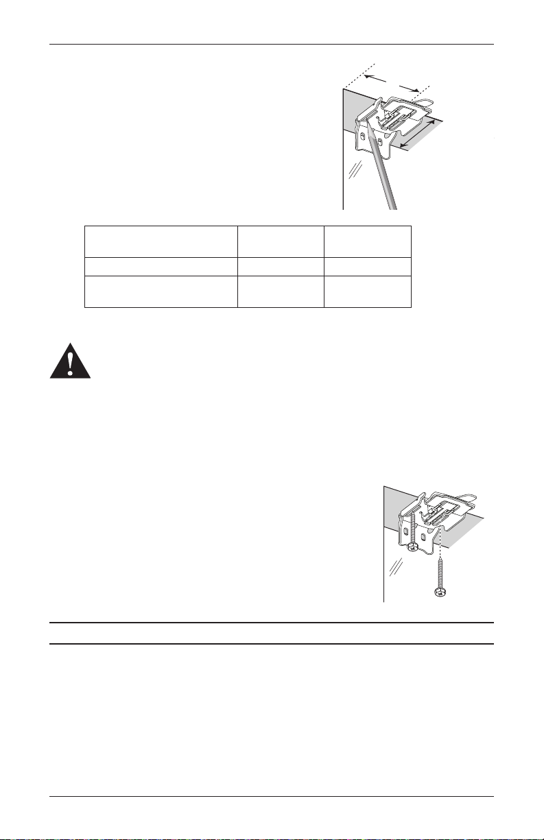
■ Mark the location of the screw holes.
➤ The minimum depth required for mounting is 2" with
a battery wand and a back cover.
1
"
/
4
➤ Minimum depth is 1
with a satellite battery pack
or 18V DC power supply and back cover.
➤ The depth required for fully recessed mounting will
vary depending on the type of headrail and vane size.
Refer to the chart below for depth requirements.
INSTALLATION
2"
Minimum
Depth
2" Battery Wand
11/4" Battery Pack or
18V DC Power Supply
Fully Recessed
Mounting Depths
Battery Wand and Back Cover 41/16" 49/16"
Satellite Battery Pack or 18V DC
Power Supply and Back Cover
Classic
Headrail
1
/2" 4"
3
Quartette® 4"
Headrail
IMPORTANT: The front edges of the installation brackets must be level and aligned.
WARNING: Failure to properly align the brackets could result in the headrail
releasing from the brackets.
3
■ Drill the screw holes using a
/32" drill bit.
CAUTION: Use drywall anchors when mounting into drywall.
■ Use a level to check that the mounting surface is level. If necessary, you can shim (not
provided) the brackets.
■ Attach the installation brackets using the screws provided.
IMPORTANT: Do not overtighten the screws. Check to
ensure the lever can be moved easily side to side. If not,
loosen the screws in one-eighth turn increments until the
lever can be moved easily.
Proceed to “STEP 2: Mount the Battery Wand and Connect the Power Cable” on page9.
5
Page 8
INSTALLATION
Window Opening
2"
Motor
Side
2"
Headrail End Marks
Space Evenly Space Evenly
18" Minimum for Battery Wand
1"
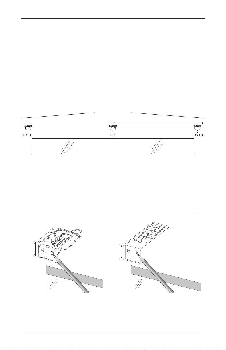
Mount the Installation Brackets — Outside Mount
■ Center the headrail over the window opening at the desired height. Use a pencil to lightly
mark each end of the headrail.
➤ Alternatively, measure the width of the headrail and use that width to mark the headrail
end points over the window opening.
■ Mark 2" in from each of the headrail end marks.
➤ If more than two installation brackets are required (see table on page 3), mark the
location of additional bracket(s) spaced evenly between the two end bracket locations.
Mount into wood whenever possible. Allow a minimum of 18" from the motor side
for the battery wand.
■ Center the installation brackets or extension brackets on your marks and mark where to drill
the screw holes.
➤ A minimum 1" flat vertical surface isrequired for the installation brackets. Extension
brackets require 1
➤ The tops of the installation brackets or extension brackets should be at the desired
height. The brackets should be level andaligned.
CAUTION: The rear of the brackets must be flush against a flat mounting surface. Do not
mount brackets oncurved molding.
1
/4".
11/4"
3
■ Drill the screw holes using a
CAUTION: Use drywall anchors when mounting into drywall.
6
/32" drill bit.
Extension
Bracket
Page 9
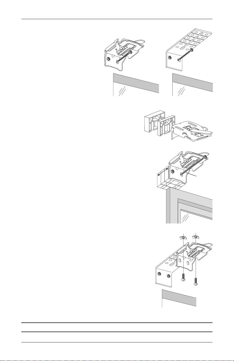
■ Attach the installation or extension
Spacer
Blocks
1
Spacer Blocks
brackets using the screws provided.
IMPORTANT: The tops of the
installation brackets or extension
brackets must be level with their
front edges aligned.
INSTALLATION
IMPORTANT: If using a battery wand, use a
1
minimum of one
/2" and one 1/4" spacer blocks per
installation bracket to provide the clearance required
for the battery wand and battery wand bracket.
■ If using spacer blocks, attach the spacer block(s) and
installation bracket to a flat vertical mounting surface
with #6screws long enough for asecure installation.
1
IMPORTANT: Do not add more than 1
/2" of clearance
using spacer blocks.
IMPORTANT: The tops of the installation brackets
must be level with the front edges aligned.
■ If using extension brackets, attach an installation bracket
to the underside of each extension bracket using the speed
nuts and screws provided.
/2"
1
/
1
Maximum
1
/4"
"
2
Speed Nuts
Longer
Screw
Screws
Proceed to “STEP 2: Mount the Battery Wand and Connect the Power Cable” on page9.
7
Page 10
INSTALLATION
batter
Back Cover Bracket
Top Tab
Bottom Tab
Back Cover
Slots
Extension
Minimum
Mount the Installation Brackets — End Mount
End mount the headrail when conventional mounting techniques will not work — for example, in
an arched window opening.
■ If you ordered a back cover, attach the back cover
brackets to the installation brackets.
➤ If a satellite battery pack or an 18V DC power
supply is used, first remove the top tab from the
back cover bracket.
➤ Snap the back cover bracket into the metal
installation bracket.
■ Mount extension brackets to each side of the opening at the desired height of the shading.
➤ The mounting surface must be vertical and flat,
not part of an arched curve.
➤ Minimum mounting surface width with a built-in
1
battery wand is 2
/8".
➤ Minimum mounting surface width with a satellite
1
battery pack or 18V DC power supply is 1
/2".
■ Attach the installation brackets to the extension
brackets using the provided screws and speed nuts.
WARNING: To end mount shadings into a surface other than a secure wall stud, use
medium to heavy-duty wall anchors (not provided) matched to the wall thickness.
Failure to mount the brackets securely may result in injury or property damage.
Remove top tab if using a satellite
y pack or an 18V DC power supply.
Bracket
Depth
1
1
/2"
■ If using the optional back cover: Install the cover into the
back cover brackets. If necessary, trim the back cover to the
desired width.
IMPORTANT: If using a battery wand, do not install the
optional back cover until the wand is installed. See “STEP 2:
Mount the Battery Wand and Connect the Power Cable” on
page9.
Back
Cover
Proceed to “STEP 2: Mount the Battery Wand and Connect the Power Cable” on page9.
8
Page 11

INSTALLATION
toward the motor end.
STEP 2: Mount the Battery Wand and Connect the Power Cable
■ Refer to the appropriate page based on your order.
➤ For a battery wand, see below.
➤ For an optional satellite battery pack, 18V DC power supply, C-size satellite battery
wand, or large DC power supply, see page 12.
Battery Wand
Install the Battery Wand Clips
■ Attach the battery wand clips to the headrail.
IMPORTANT: Position the clips close to the power cable.
Mount the Battery Wand into the Battery Wand Clips
■ Position the battery wand with its socket toward
the motor end of the shading.
■ Push the battery wand straight up into the
battery wand clips until it snaps into place.
Check to make sure the battery wand is secure.
CAUTION: Be sure the cables do not
become pinched by the battery wand clips
during installation. Damage or overheating of
components could result.
Place the socket
Plug the Power Cable into the Battery Wand
NOTE: When power is connected to the motor, a green LED inside the programming button
housing will flash to indicate the shading is ready for operation.
■ From the back of the shading headrail, connect
the power cable (from the motor side) into the
socket on the battery wand.
Power
Cable
Battery
Wand
9
Page 12

INSTALLATION
Lever
STEP 3: Install the Shading
Install the Optional Back Cover (If Applicable)
The optional back cover is used on inside and end mounts only.
■ Install the back cover into the back cover brackets on the rear of the installation brackets, as
shown. If necessary, trim the back cover to the desired width.
➤ On shadings with battery wand(s), the top of the back cover fits onto the top tab of the
back cover bracket.
IMPORTANT: If using a battery wand, do not install the optional back cover until the
wand is installed. Refer to “STEP 2: Mount the Battery Wand and Connect the Power
Cable” on page9.
➤ On all other shadings, the top tab has been removed and installs closer to the installation
bracket.
Back
Cover
Back
Cover
Mount the Headrail
■ Peel back the protective covering from the top of the fabric-covered headrail. Leave the rest
of the protective covering on the front of the headrail.
■ Position the shading so that the front faces you.
Headrail
■ Slide the headrail into the installation
brackets so the edge of the headrail
is between the lever and the bracket,
asshown.
■ Firmly push the headrail into each bracket until it clicks and the
Installation
Bracket
Slide the Headrail
Between the Lever
and the Bracket
lever snaps to the right side of the bracket.
IMPORTANT: Carefully pull on the headrail at each bracket to ensure it is
installed securely.
■ Completely remove the protective covering from the fabric-covered headrail.
10
Page 13

INSTALLATION
Remove
Backing
Overhead View
Dots
Dust Cover Installed
Attach the Optional Dust Cover (If Applicable)
The dust cover is used to protect the top of the headrail from exposure on outside mounted
shadings.
■ Cut the dust cover to desired width.
■ Remove the paper backing on one side of the hook and loop
fastener dots.
■ Apply the dots to the installation brackets on each end of theshading.
No Dust Cover
■ Remove the remaining paper backing from the dots.
■ Center the dust cover over the top of the shading, above the previously placed dots.
■ Press the dust cover down onto the dots.
Paper
Proceed to “Attach Magnetic Hold-Down Brackets (Optional)” on page15
or “Testing the Shading” on page16.
11
Page 14

INSTALLATION
Socket
Socket
STEP 4: Connect the Power Source, If Applicable
NOTE: When power is connected to the motor, a green LED inside the programming button
housing will flash to indicate the shading is ready for operation.
■ Refer to the appropriate page based on your order.
➤ For an optional satellite battery pack, see below.
➤ For an optional 18V DC power supply, see page 13.
➤ For an optional 18V DC power supply with daisy-chain connections, see page 14.
➤ For an optional C-size satellite battery wand or large DC power supply, see the
instructions that came with the unit.
Satellite Battery Pack
Mount the Satellite Battery Pack
■ Decide where you want to mount the satellite battery pack. A satellite battery pack may be
mounted in any orientation.
■ Mark the screw holes for the wall mount bracket.
3
■ Drill the screw holes using a
/32" drill bit.
■ Remove the backing from the double-sided tape. Press the
bracket into place.
■ Attach the bracket using the screws provided.
■ Position the battery wand so the power cable is easily connected to the socket.
■ Snap the battery wand into the wall mount bracket.
Wall Mount Bracket
■ Install the cover with the slot aligned to the socket in the battery wand.
Slot
Battery Wand Cover
12
Page 15

■ Plug the power cable from the shading into
from Shading
the extension cable.
■ Plug the other end of the extension cable
into the socket in the battery wand.
Proceed to “STEP 3: Install the Shading” on page10.
18V DC Power Supply
Connect the Power Supply
■ Plug the power cable from the shading
into the extension cable.
■ Plug the other end of the extension cable
into the 18V DC power supply.
■ Plug the 18V DC power supply into a
standard outlet.
■ Secure the extension cable using wire
retainers (not supplied). If hiding the cable
behind the shading, make sure it does
not impede the operation of theshading.
■ Space the wire retainers approximately
15" apart along the power supply cable,
as shown.
WARNING: Keep cords and small
parts out of the reach of children.
They can wrap cords around their
necks and STRANGLE. They can
also put small parts in their mouths
and CHOKE.
WARNING: Electric shock and/or
a fire hazard may occur, if not properly installed.
Power Cable
Power Cable
from Shading
Extension
Cable
18V DC
Power
Supply
Battery Wand Cover
15"
Maximum
INSTALLATION
Extension
Cable
Wire Retainers
Proceed to “STEP 3: Install the Shading” on page10.
13
Page 16

INSTALLATION
Power Cable from Shading
Connector
wer Supply
18V DC Power Supply with Daisy-Chain Connections
The daisy-chain feature allows up to three PowerView® shadings to be powered by a single 18V
DC power supply. However, each shading can operate independently. The daisy-chain feature is
only available with the 18V DC power supply option.
■ Route the power cables from each shading to the connector, using an extension cable, if
necessary.
■ Plug an extension cable into the connector and plug the cable into the 18V DC power supply.
Two extension cables and two connectors are used for three shadings.
Power Cable from Shading
Extension
Cable
■ Plug the 18V DC power supply into a standard outlet.
Proceed to “STEP 3: Install the Shading” on page10
14
18V DC Po
Page 17

Attach Magnetic Hold-Down Brackets (Optional)
Bottom
Outside Mount
■ Lower the shading, keeping the vanes closed.
■ Place the magnetic hold-down brackets onto the bottom rail just inside
the end caps, oriented as shown.
■ Hold the brackets while opening and closing the vanes. (It may be
necessary to have someone assist you.) Adjust the brackets to the best
overall position.
■ Mark the screw locations using one of the mounting options shown
below.
➤ The screw should be placed in the middle of the channel. This will
allow for adjustment.
INSTALLATION
Rail
Hold-Down
Bracket
■ Drill the screw holes using a
■ Attach the hold-down brackets to the mounting surface
■ If necessary, adjust the bracket height by loosening the
Preferred Alternate
Inside Mount
Preferred Alternate
3
/32" drill bit.
using the screws provided.
screw and sliding the bracket up or down.
Adjust the
bracket
up or down
using the
channel.
15
Page 18

OPERATION
OPEN
Group 3
Group 4
Testing the Shading
Use the programming button to test the shading and
ensure that the motor and power source are working
correctly.
■ Press the programming button to lower the
shading. If the shading does not operate, see
“Troubleshooting” on page20.
■ Test vane operation by pressing the
programming button to open the vanes and then
pressing it again to close the vanes.
■ After the vanes are fully closed, press the
programming button to raise the shading.
CAUTION: When raising the shading for the first time, observe how the fabric rolls up into
the headrail. It should roll up evenly. If the bottom rail is not level or the shading starts to rub
against either window jamb, immediately press the programming button to stop the shading.
See “Adjust the Bottom Rail Weight” on page23.
Using the PowerView® Remote
First, activate the remote by pulling both plastic tabs from the back battery compartment.
Group 5
STOP
(Press and hold for
programming mode)
Group 6
RIGHT ARROW
Tilts vanes open
Favorite
(Shading/vane position)
LEFT ARROW
Tilts vanes closed
Group 2
Group 1
CLOSE
IMPORTANT: If you have more than one remote, see “Adding Additional Remote(s) to the
®
PowerView
Shade Network” in the PowerView Motorization Remote Control Guide.
16
Page 19

OPERATION
Joining a Shading to a Group
IMPORTANT: The shading will not operate using the remote until it has been joined to a group.
1. Press and hold ■ STOP on the remote until the indicator lights blink (approximately
6 seconds). The remote is now in program mode.
2. Press the desired group number (1 – 6) on the remote. The backlit group number will flash to
show it is selected.
3. While pressing the programming button on the shading, press ▲ OPEN on the remote. The
green light flashes once and the shading will move slightly twice (up, down, or down, up) to
indicate the shading has joined the group. Release the programming button.
4. Press and hold ■ STOP on the remote until the indicator lights stop blinking (approximately
6 seconds).
Basic Operation
■ To wake up the remote, simply pick it up or press ■ STOP. The last group(s) selected will be
highlighted and active.
■ Press “all” or groups 1 – 6 to select specific shading(s) to move. Selected group button(s)
will light to show they are selected.
➤ Multiple group buttons may be selected at a time.
➤ To deselect a group, press the group button again. The backlight for that group button
will go out.
■ Press ▼ CLOSE to lower the selected shading(s).
■ Press the right arrow to open the vanes.
■ Press the left arrow to close the vanes.
■ Press ▲ OPEN to raise the selected shading(s).
■ Press ■ STOP to stop shading or vane movement anywhere along its travel.
■ While a shading is in motion, press the opposite of shading motion (▲ OPEN or ▼ CLOSE)
to reverse direction.
■ Press ♥ FAVORITE to send selected shading(s) to your preset “favorite” position. Refer to the
PowerView
favorite position is the shading at 50% open.
®
Motorization Remote Control Guide on how to set a favorite position. The default
Operating Tips
1. When the shading is raised, pressing the right arrow will first lower the shading and then
open the vanes.
2. When the shading is lowered with the vanes open, pressing ▲ OPEN will first close the vanes
and then raise the shading all the way.
17
Page 20

OPERATION
Change the Closed Vane Adjustment Position
The closed vane adjustment position is set for each shading at the factory and normally does
not require readjustment. Use the following instructions to reset the position for shadings that
may need additional adjustment. The objective is to get the longest drop of the shading with the
vanes fully closed.
There is a one minute time limit while the shading is in fine adjustment mode. The shading must
be moved at least once during each minute to prevent the mode from timing out.
1. On the remote, press the group number of the shading (1–6), then press the left arrow to
fully lower the front shading and close the vanes.
2. While pressing the programming button on the shading, press the left arrow on the remote,
then release the programming button on the shading. The programming button light will turn
on solid red to indicate the shading is in fine adjustment mode.
NOTE: If the shading moves, or the programming button flashes green, repeat steps 1
and 2.
3. Use ▲ OPEN, ■ STOP, and ▼ CLOSE on the remote to lower the shading or raise the
shading as far as possible without opening the vanes. The shading will move in slow speed
while in fine adjustment mode.
NOTE: In the vanes closed position, the bottom rail will be slightly raised from the window
sill, which is normal.
4. Set the new adjustment position. Press and hold ■ STOP on the remote for approximately
6 seconds, until the indicator lights on the remote start blinking.
5. Save the new adjustment position and exit fine adjustment mode. While pressing the
programming button on the shading, press the left arrow on the remote, then release the
programming button. The red light turns off, the green light flashes twice, and the shading
moves slightly twice to confirm that the new setting was accepted.
6. Exit program mode on the remote. Press and hold ■ STOP on the remote until the indicator
lights on the remote stop blinking (approximately 6 seconds), or let the remote time out
(approximately 20 seconds).
7. Test the shading to confirm the new adjustment position.
18
Page 21

OPERATION
Further Operation and Programming Information
PowerView® Pebble® Remote and/or PowerView Surface Remote Operation
For information regarding operation and programming of the PowerView remote, refer to your
PowerView Motorization
®
Remote Control Guide or to the online PowerView Step-by-Step Guide
at hunterdouglas.com/operating-systems/motorized/powerview-motorization/manuals.
®
PowerView
Scene Controller
For information regarding operation and programming of the PowerView Scene Controller, refer
to your PowerView Motorization Scene Controller Guide or to the online PowerView Step-by-Step
Guide at hunterdouglas.com/operating-systems/motorized/powerview-motorization/
manuals.
®
PowerView
The PowerView Hub
App Operation
®
is required for PowerView App operation. For information regarding setup
and operation using the PowerView App, refer to the online PowerView Step-by-Step Guide at
hunterdouglas.com/operating-systems/motorized/powerview-motorization/manuals.
Resetting the Shading (If Necessary)
Calibration Reset
The calibration reset is used to recalibrate the shading’s travel limits.
1. Press and hold the programming button for approximately 6 seconds. The shading will move
slightly. Release the programming button (the light flashes red).
2. The shading will raise to its fully open position to reestablish the upper travel limit, then lower
to the fully closed position with vanes open to reestablish the lower travel limit. The shading
will move slightly twice (up, then down) to indicate that the travel limits were recalibrated.
Resetting Shading Programming
The programming reset erases shading programming from memory, including group
assignments, preventing input devices from operating the shading. The primary use is to correct
group and network assignments during installation. The reset does not affect travel limits or the
favorite position.
1. Press and hold the programming button for approximately 12 seconds. The shading will move
slightly after 6 seconds, then again after 12 seconds. Release the programming button (the
light flashes red). The light then flashes a series of green and red to indicate that shading
programming is erased from memory.
2. Refer to “Joining a Shading to a Group” on page17 to program the shading to a group.
19
Page 22

OPERATION
Troubleshooting
If your shading is not operating correctly:
■ First review the guide that came with your control device.
■ Refer to the following troubleshooting procedures for specific solutions for your shading.
For questions, please contact Hunter Douglas Consumer Support at 1-888-501-8364.
Problem The shading will not fit into the installation brackets.
Solution
If the shading has a battery wand, check that the wand is not interfering with the
installation brackets.
Check that the installation brackets are level and aligned. Adjust and/or shim to
level, if necessary.
Be sure the heads of the mounting screws are flush against the installation bracket.
Check that the headrail is completely inserted into the installation brackets. See
“STEP 3: Install the Shading” on page10.
Problem The shading does not operate using the programming button.
Solution
Unplug the power cable from the motor, then plug it back in. A green LED inside the
programming button housing should flash to indicate the motor has power.
Check that the batteries in the battery wand, satellite battery pack, or C-size
satellite battery wand are correctly inserted and fresh.
Check that the battery wand, satellite battery pack, C-size satellite battery wand, or
18V DC power supply is securely connected to the power cable and the cables are
not pinched or caught in the headrail or installation brackets.
Problem Batteries in the battery wand need to be replaced.
Solution
Replace the batteries in the battery wand.
Squeeze the cap latch to release
the cap and remove the cap
from the battery wand.
Install the batteries according to
the instructions on the battery
wand label.
Press the cap on until it latches.
NOTE:
Hunter Douglas recommends AA alkaline batteries for use with our battery-
Squeeze
Cap
Latch
powered shadings. These will provide more than one year of operation, depending
on usage. Lithium and rechargeable batteries are not recommended.
Battery
Wand
20
Page 23

Problem The shading is not responding to the PowerView® remote.
k
Limit StopHeadrail
OPERATION
Solution IMPORTANT:
A shading will not operate using the remote until it has been joined
to a group.
Check that the correct group number is selected.
Check that the batteries in the remote are correctly inserted and are fresh. The LEDs
■
that backlight the remote should come on full bright when
STOP is pressed.
Problem The vanes do not open when the shading is first operated.
Solution
Make sure the shading is completely lowered.
Open and close the shading several times to help open the vanes. If necessary,
gently pull down on the bottom rail.
Problem The shading is hard to raise or lower, or the bottom rail does not stop at the
top limit.
Solution
Check the adjustment position of both
limit stops. The top illustration shows the
correct adjustment. The limit stop catches
the bottom rail, and the bottom of the limit
stop is slightly above or barely touching
Fabric Roll
Bottom
Rail
the fabric roll.
In the second illustration, the limit stop
adjustment is too tight. The fabric may not
drop freely and could even be damaged
when the shading is raised. To correct
Pull Bac
to Adjust
this, the limit stop should be adjusted one
step up. Simply pull back on the rear of
the limit stop to adjust its position.
Too Tight —
Adjust One Step Up
In the bottom illustration, the adjustment
is too loose. The bottom rail can slip under
the limit stop. If the bottom rail rotates
through the headrail, it must be backed
Pull Back
to Adjust
out before adjusting the limit stop.
IMPORTANT:
be adjusted to the same position or else
skewing may occur.
Both limit stops must
Too Loose —
Adjust One Step Down
21
Page 24

OPERATION
Problem The bottom rail does not raise or lower completely, or its location when fully
lowered has changed over time.
Solution The batteries may be low in the battery wand, satellite battery pack, or C-size
satellite battery wand. Replace the batteries.
Check that the battery wand, satellite battery pack, C-size satellite battery wand,
or 18V DC power supply is securely connected to the power cable and the cables
are not pinched or caught in the headrail or installation brackets.
Check that there is clearance between the ends of the shading and the window
casement on inside mounts.
Check if the fabric rolls up evenly into the headrail. If not, see “Adjust the Bottom
Rail Weight” on page23.
Reset the travel limits. See “Resetting the Shading (If Necessary)” on page19.
®
See the PowerView
programming troubleshooting solutions.
Problem Adjacent shadings do not roll up evenly.
Solution It is considered normal if the roll-up on both shadings is within
other. If one shading rolls up tighter than another, lower and raise both shadings
several times.
Reset the shading. See “Resetting the Shading (If Necessary)” on page19.
Check that the shading fabric is not catching on any brackets or components.
Check that the fabric winds evenly and does not rub against the headrail. If
uneven, see “Adjust the Bottom Rail Weight” on page23.
Motorization Remote Control Guide for operation or
5
/16" of each
22
Page 25

OPERATION
Weight
Weight
Fabric Roll
Problem The shading raises or lowers unevenly, the fabric rubs against one end of the
headrail, or the bottom rail is uneven when fullyraised.
Solution Check that the window is square by measuring the diagonals.
Check that the installation brackets are level. Shim to level, ifnecessary.
Adjust the Bottom Rail Weight
■ Release the weight clips by inserting
a flat blade screwdriver into the
weight clip and turning clockwise.
Clip
Bottom Rail
Weight
Clip
■ Move the weight in 1" increments toward the side where the fabric
isgathering.
Gathered
Fabric
Move Weight
■ Secure the weight clips in position by turning them counterclockwise after
making the adjustment.
■ Test and, if necessary, adjust again.
23
Page 26

OPERATION
Problem The vanes do not close fully when the shading stops in the lowest position.
Solution The shading should be programmed to stop in its lowest position with the vanes
closed. A small distance between the front and back fabric facings in the fully
closed position is normal.
■ If this distance is excessive or moves over time, open the shading to its full
“vane open” position and try again. If this does not correct the problem, reset
the bottom limit. See “Resetting the Shading (If Necessary)” on page19.
®
■ See the PowerView
programming troubleshooting solutions.
Problem The shading raises from the sill when the vanes areclosed.
Solution A small gap between the sill and the bottom of the shading is normal in the fully
lowered “vane closed” position. The gap is necessary to allow for the unimpeded
movement of the bottomrail.
■ If this distance is excessive or moves over time, open the shading to its full
“vane open” position and try again. If this does not correct the problem, reset
the bottom limit. See “Resetting the Shading (If Necessary)” on page19.
■ See the PowerView Motorization Remote Control Guide for operation or
programming troubleshooting solutions.
Motorization Remote Control Guide for operation or
Problem The front fabric appears to cling to the back fabric.
Solution Lightly apply a static spray for home furnishings. Follow the manufacturer’s
directions. Allow the shading to dry in the fully lowered position. If necessary,
reapply the static spray each time the shading is professionally cleaned.
24
Page 27

Removing the Shading
Installation Bracket
Move the lever to the left
to release the shading.
Top View
■ Fully raise the shading.
■ Disconnect the power source from the power cable at the
back of the shading.
■ Move each lever of the installation brackets to the left to
release the shading.
CAUTION: A flat blade screwdriver can be used to move
the lever. Be very careful not to tear or damage the fabric.
➤ If the lever is inaccessible
or inoperable, lower the shading until
you can see the underside of the
bracket. Carefully reach a small flat
blade screwdriver behind the shading
to the tab on the bottom of the
bracket between the screw holes.
➤ Push the tab away from the shading
and pull the headrail to release it
from the bracket.
■ Carefully pull the headrail to completely
remove the shading from the brackets.
Underside of
Bracket
CARE
Tab
End Cap
Cleaning Procedures
Silhouette® and Nantucket™ Window Shadings are made of 100% polyester, which means they
are inherently durable and resilient. However, care must be taken to avoid wrinkling the fabric,
particularly where the vanes meet the facings.
The Palette® Fabric-Covered Headrail
■ Spot-clean the headrail using a sponge or delicate cloth, cool distilled water and a mild soap
solution; handle with care as you would any fine fabric.
Dusting
■ Regular light dusting with a feather duster is all the cleaning needed in most circumstances.
Vacuuming
■ Use a low suction, hand-held vacuum for more thorough dust removal.
25
Page 28

CARE
Forced Air
■ Blow away dirt and debris between the vanes using clean compressed air.
Spot-Cleaning
Do not spot-clean anything other than the Palette® Fabric-Covered Headrail on Silhouette® or
Nantucket
™
Window Shadings.
Ultrasonic Cleaning
Silhouette and Nantucket Window Shadings can be ultrasonically cleaned by a professional,
with the exception of Boardwalk
™
ClearView
The Matisse Collection
Traditions
Originale™, ClearView Tapestry™, East Bay™, India Silk,
®
™
Light Dimming.
, Misty Harbor™, Mystere, Sankaty™, Sun Porch™, and
■ Specify that a mild detergent solution be used.
■ Never immerse the headrail in the solution.
■ Allow the shading to dry in the completely lowered position.
™
, all Bon Soir™ fabrics, Brio™, Brant Point™,
Injection/Extraction
Silhouette and Nantucket Window Shadings can be professionally cleaned using the injection/
extraction method.
■ Use only the dry method of injection/extraction for all Bon Soir fabrics, Misty Harbor, and
Traditions Light Dimming.
■ Never immerse the headrail in the solution.
Electrostatic Cleaning
Do not use electrostatic cleaning wipes on any Silhouette or Nantucket Window
Shadings.
A Note About Hardware for The Alustra® Collection
Gold Radiance™, Silver Reflection™, Bronze Shimmer™, and Champagne Shine™ hardware
finishes can be spot-cleaned with lukewarm water and a gentle soap. Do not use alcohol, baby
wipes or alkaline cleansers. These may stain or destroy the finish.
A Note About Silhouette and Nantucket Fabrics
As with all textiles, Silhouette and Nantucket fabrics are subject to some variations. Slight
wrinkling, puckering, or bowing is inherent to this textile product and should be considered
normal, acceptable quality. These characteristics are not usually visible from the front or rear
butmay be visible from a side angle.
Precautions should be taken to reduce exposure to harsh environmental elements, such as
salt air. Continuous exposure through open windows and doors will accelerate the fabric
deterioration.
26
Page 29

DECLARATIONS
U.S. Radio Frequency FCC Compliance
FCC ID information is located behind the motor-side end cap. The end cap may be removed to view this
information.
This device complies with Part 15 of the FCC Rules. Operation is subject to the following two conditions:
(1) This device may not cause harmful interference, and
(2) This device must accept any interference received, including interference that may cause undesired operation.
This equipment has been tested and found to comply with the limits for a Class B digital device, pursuant to Part
15 of the FCC Rules. These limits are designed to provide reasonable protection against harmful interference in a
residential installation. This equipment generates, uses and can radiate radio frequency energy and, if not installed
and used in accordance with the instructions, may cause harmful interference to radio communications. However,
there is no guarantee that interference will not occur in a particular installation. If this equipment does cause
harmful interference to radio or television reception, which can be determined by turning the equipment off and
on, the user is encouraged to try to correct the interference by one or more of the following measures:
• Reorient or relocate the receiving antenna.
• Increase the separation between the equipment and receiver.
• Connect the equipment into an outlet on a circuit different from that to which the receiver is connected.
• Consult the dealer or an experienced radio/TV technician for help.
Any changes or modifications not expressly approved by the party responsible for compliance could void the user’s
authority to operate the equipment.
This equipment complies with FCC radiation exposure limits set forth for an uncontrolled environment and meets
the FCC radio frequency (RF) Exposure Guidelines. This equipment should be installed and operated keeping the
radiator at least 20 cm or more away from person’s body. RF Exposure requirements are met when installed in
mobile equipment. This module cannot be installed in portable equipment without further testing and a change to
FCC’s grant of authorization.
Industry Canada
Under Industry Canada regulations, this radio transmitter may only operate using an antenna of a type and
maximum (or lesser) gain approved for the transmitter by Industry Canada. To reduce potential radio interference
to other users, the antenna type and its gain should be so chosen that the equivalent isotropically radiated power
(e.i.r.p.) is not more than that necessary for successful communication.
This device complies with Industry Canada licence-exempt RSS standard(s). Operation is subject to the following
two conditions: (1) this device may not cause interference, and (2) this device must accept any interference,
including interference that may cause undesired operation of the device.
Class B Digital Device Notice
This Class B digital apparatus complies with Canadian ICES-003, RSS-Gen and RSS-210.
CAN ICES-3 (B)/NMB-3(B)
This equipment complies with IC radiation exposure limits set forth for an uncontrolled environment and meets
RSS-102 of the IC radio frequency (RF) Exposure rules. This equipment should be installed and operated keeping
the radiator at least 20 cm or more away from person’s body.
European Conformity
We, the undersigned,
Hunter Douglas Window Fashions
One Duette Way, Broomfield, CO 80020, USA
Hunter Douglas Europe B.V.
Piekstraat 2, 3071 EL Rotterdam, The Netherlands
certify and declare under our sole responsibility that assembly PV13 conforms with the essential requirements of
RED 2014/53/EU.
A copy of the original declaration of conformity may be found at:
www.hunterdouglas.com/RFcertifications.
27
Page 30

Notes
Page 31

Page 32

The Hunter Douglas® Lifetime Guarantee is an expression of our desire to provide a thoroughly satisfying
experience when selecting, purchasing and living with your window fashion produc ts. If you are not thoroughly
satisfied, simply contact Hunter Douglas at (888) 501-8364 or visit hunterdouglas.com. In support of this policy
of consumer satisfaction, we offer our Lifetime Limited Warranty as described below.
COVERED
BY A LIFETIME LIMITED WA RRANTY
• Hunter Douglas window fashion products are
covered for defects in materials, workmanship
or failure to operate for as long as the original
retail purchaser owns the product (unless shorter
periods are provided below).
• All internal mechanisms.
• Components and brackets.
• Fabric delamination.
• Operational cords for a full 7 years from the
date of purchase.
• Repairs and/or replacements will be made with
like or similar parts or products.
• Hunter Douglas motorization components are
covered for 5 years from the date of purchase.
• Any conditions caused by normal wear and tear.
• Abuse, accidents, misuse or alterations to the
• Exposure to the elements (sun damage, wind,
• Failure to follow our instructions with respect
• Shipping charges, cost of removal and reinstallation.
NOT COVERED
BY A LIFETIME LIMITED WA RRANTY
product.
water/moisture) and discoloration or fading
over time.
to measurement, proper installation, cleaning
or maintenance.
Hunter Douglas (or its licensed fabricator/distributor) will repair or replace the
window fashion product or components found to be defective.
TO OBTA IN WARRANTY SERV ICE
1. Contact your original dealer (place of purchase) for warranty assistance.
2. Visit hunterdouglas.com for additional warranty information, frequently asked questions and access to service locations.
3. Contact Hunter Douglas at (888) 501-8364 for technical support, certain parts free of charge, for assistance in obtaining
warranty service or for further explanation of our warranty.
NOTE: In no event shall Hunter Douglas or its licensed fabricators/distributors be liable or responsible for incidental
or consequential damages or for any other indirect damage, loss, cost or expense. Some states do not allow the exclusion or
limitation of incidental or consequential damages, so the above exclusion or limitation may not apply to you. This warranty
gives you specific legal rights, and you may also have other rights which vary from state to state.
Different warranty periods and terms apply for commercial products and applications.
7/185107647000
 Loading...