

Page 1
Installation • Operation • Care
Luminette® Privacy Sheers
PowerView™ Motorization
Page 2

CONTENTS
Questions?
Call Hunter Douglas Consumer Support at
1-888-501-8364.
© 2016 Hunter Douglas. All rights reserved. All trademarks used herein are the property of Hunter Douglas
or their respective owners.
Getting Started:
Product View ............................................................................ 1
Tools and Fasteners Needed ...................................................... 2
Unpack the Components ........................................................... 2
Installation:
Mount the Installation Brackets — Inside/Ceiling Mount .............. 4
Mount the Installation Brackets — Outside Mount ...................... 7
Bracket Locations — Corner and Bay Windows ........................ 11
Install the SofTrak
™
Headrail .................................................... 12
Side-by-Side (Abutted) Installations (Simulated Split Stack) ........ 13
Connect PowerView
™
Components ........................................... 14
Test Headrail Operation .......................................................... 15
Attach the Fabric Panel(s) ........................................................ 16
Operation:
Using the PowerView Remote ................................................. 19
Resetting the Sheer ................................................................. 20
Troubleshooting ...................................................................... 21
Care:
Removing the Fabric/Motor/Headrail ........................................ 23
Cleaning Procedures ............................................................... 25
Additional Product Enhancements ............................................ 27
Declarations .......................................................................... 28
Lifetime Guarantee ..................................................Back Cover
Page 3
GETTING STARTED
1
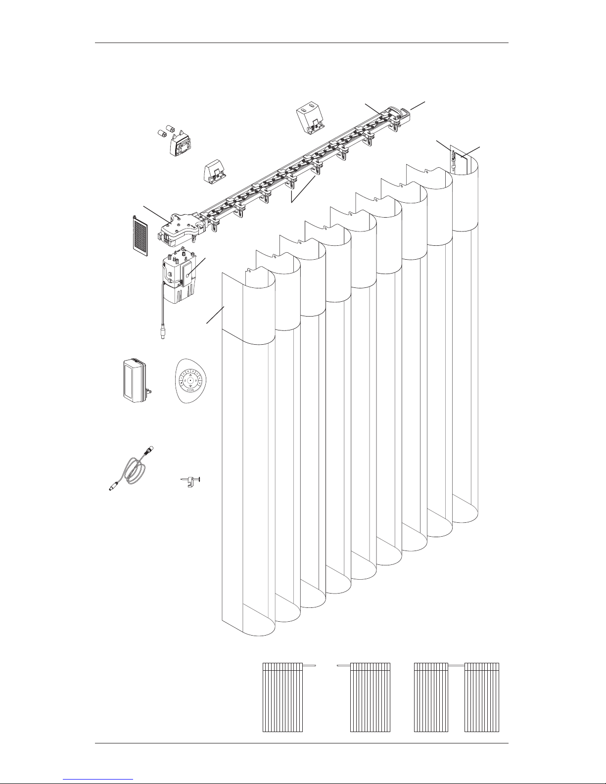
Product View
Left Stack Right Stack Split Stack
SofTrak
™
Headrail
Swivel
Plate
Rivet
Swivel
Arm
Left Stack Shown
Inside/Ceiling
Mount Bracket
Installation Bracket
Faceplate
DC Power
Supply
DC Power
Supply Cable
C-Clip
Modular
Motor
Assembly
Manual
Control
Button
PowerView
™
Remote
Drive Assembly
Spacer Block
with Bushings
Pinion
Clips
Swivel
Plate
End
Treatment
Page 4
2
GETTING STARTED
Thank you for purchasing Luminette® Privacy Sheers with PowerView™ Motorization. With proper
installation, operation, and care, your new sheers will provide years of beauty and performance.
Please thoroughly review this instruction booklet and the packing list included with your order
before beginning the installation.
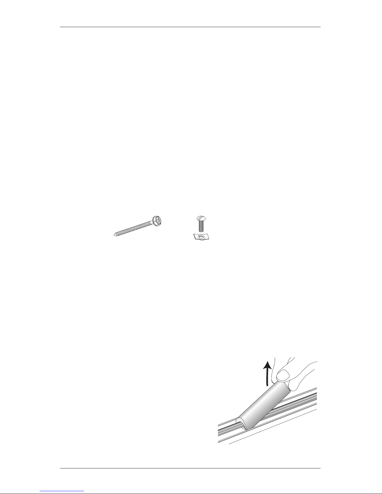
Tools and Fasteners Needed
■ Flat blade and Phillips screwdrivers
■ Measuring tape and pencil
■ Power drill,
3
/32" drill bit,
and
1
/4" hex driver
In addition, you will need fasteners designed to work with your specific mounting surface(s).
■ #6 Hex Head Screws (Provided). Two 1
1
/2" screws are provided per installation bracket.
■ Speed Nuts and Screws (Provided). Extension brackets come with screws and speed nuts.
■ Drywall Anchors (Not Provided). Use drywall anchors when mounting into drywall.
Unpack the Components
■ Make sure you have clean hands or wear disposable gloves when handling Luminette fabric.
To avoid wrinkling the fabric, do not fold it or drape it over furniture.
■ One or more fabric panels may be packaged in a carton.
■ The fabric panels are rolled around a cardboard tube. Do not remove the protective
wrapping until starting the “Attach the Fabric Panel(s)” step on page 16.
■ Remove the SofTrak
™
headrail system and installation hardware from inside the carton.
■ Remove the foam supports from the tilt shaft inside
the headrail. Rotate the supports in either direction
until they can be pulled off.
IMPORTANT: With wider fabrics, the SofTrak
headrail may be shipped separately.
Remove
Foam Supports
■ Level (laser level is recommended)
■ Needlenose pliers
■ Utility knife and scissors
Speed Nut
and Screw
(Two Provided with
Each Extension Bracket)
#6 x 1
1
/2"
Hex Head Screw
(Provided)
Page 5
GETTING STARTED
3
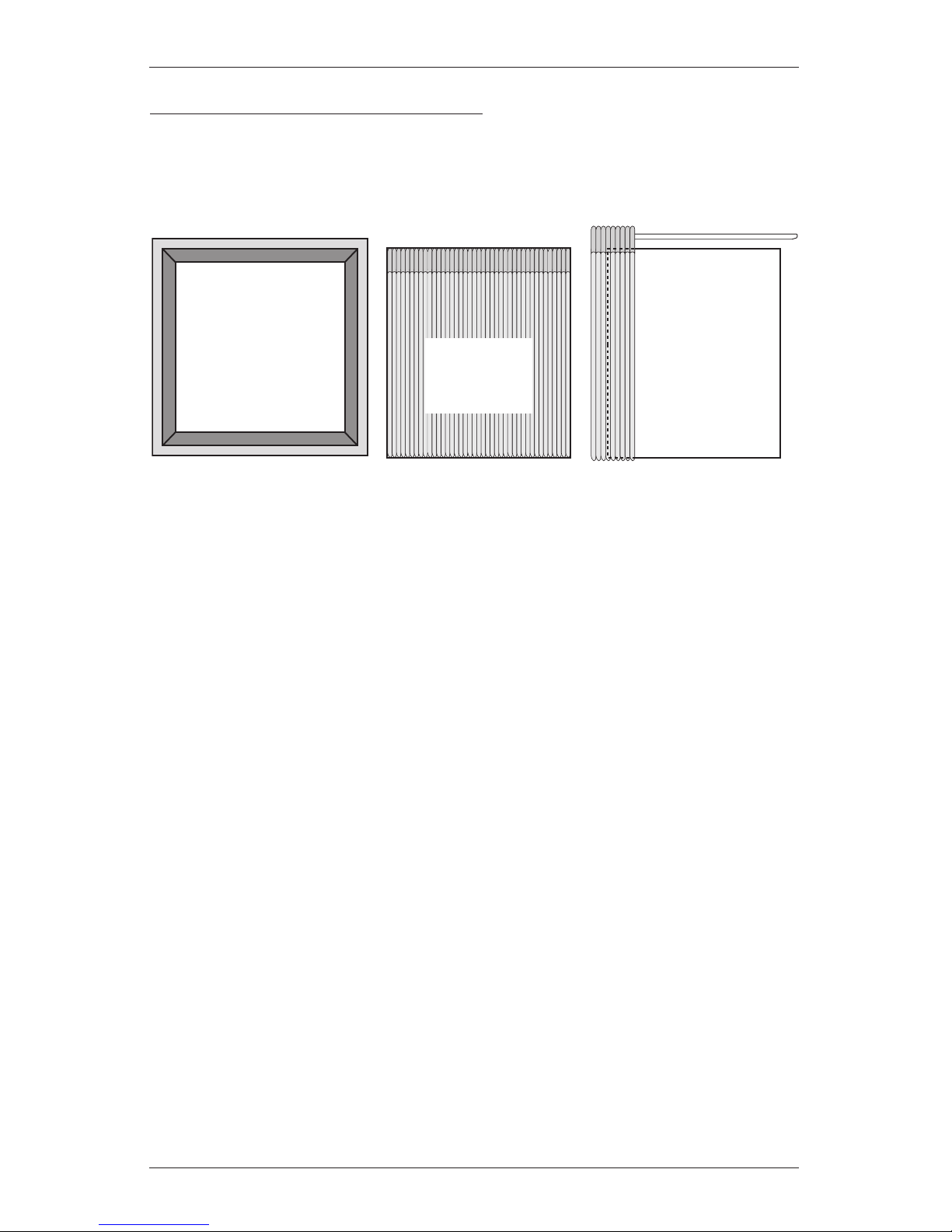
Mounting Types and Window Terminology
If the installation brackets are mounted correctly, the rest of the installation process follows
easily. To prepare for this important first step, review the mounting types and basic window
terminology illustrated below.
■ For proper operation, the fabric must clear all obstructions, including window cranks,
handles, and moldings.
➤ Replace protruding window cranks with T-cranks, as needed.
■ Refer to the appropriate page below based on your order:
➤ Inside/Ceiling Mount — Page 4
➤ Outside Mount — Page 7
Collectively, the sill and
jambs are called the
“window casement.”
Molding (or Wall)
Head Jamb
Sill (or Floor)
Jamb Jamb
Inside Mount
Sheer fits
within window
or door opening.
Outside Mount
Sheer mounts
outside window
or door opening.
Page 6
INSTALLATION
4
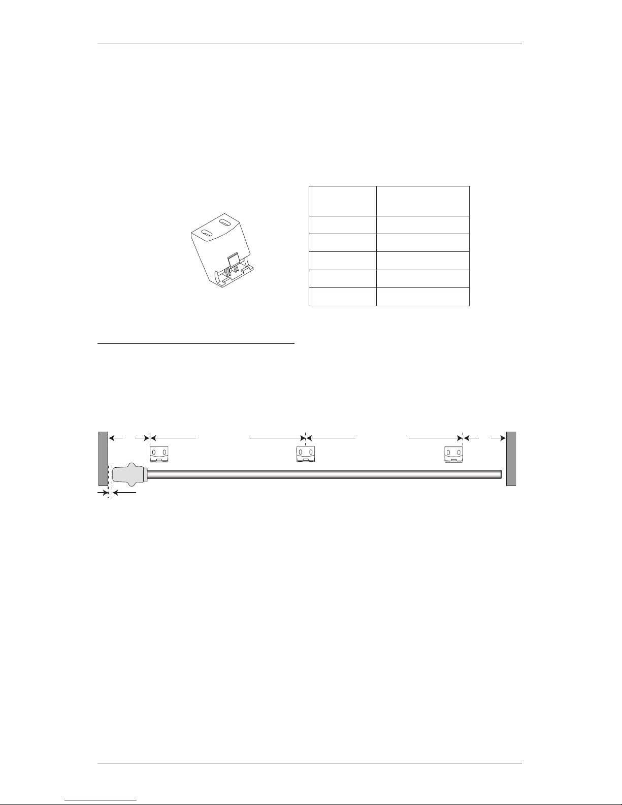
Mount the Installation Brackets — Inside/Ceiling Mount
If you are mounting on corner or bay windows, refer to “Bracket Locations — Corner and Bay
Windows” on page 11 for specific bracket locations. Return to this page after identifying
the bracket locations.
■ Your order will include the appropriate number of inside/ceiling mount installation brackets.
The number of installation brackets required varies with headrail width, as shown below.
Measure and Mark Bracket Locations
■ Mark 5" from each jamb on the mounting surface.
➤ If more than two installation brackets are required (see table above), mark the locations
of additional bracket(s) spaced evenly between the two end brackets.
CAUTION: Installation brackets should be fastened into wood whenever possible. Use drywall
anchors when mounting into drywall. When attaching brackets into drywall, additional brackets
may be required to keep the headrail level after the fabric is attached.
Inside/Ceiling Mount
Installation Bracket
Headrail
Width
Brackets Required
Up to 40" 2
40
1
/8" – 70" 3
70
1
/8" – 96" 4
96
1
/8" – 155" 6
155
1
/8" – 192" 8
Top View
Bracket
Jamb
Jamb
SofTrak
™
Headrail
Space EvenlySpace Evenly5" 5"
5
/8" Gap Required
Motor
Page 7
INSTALLATION
5
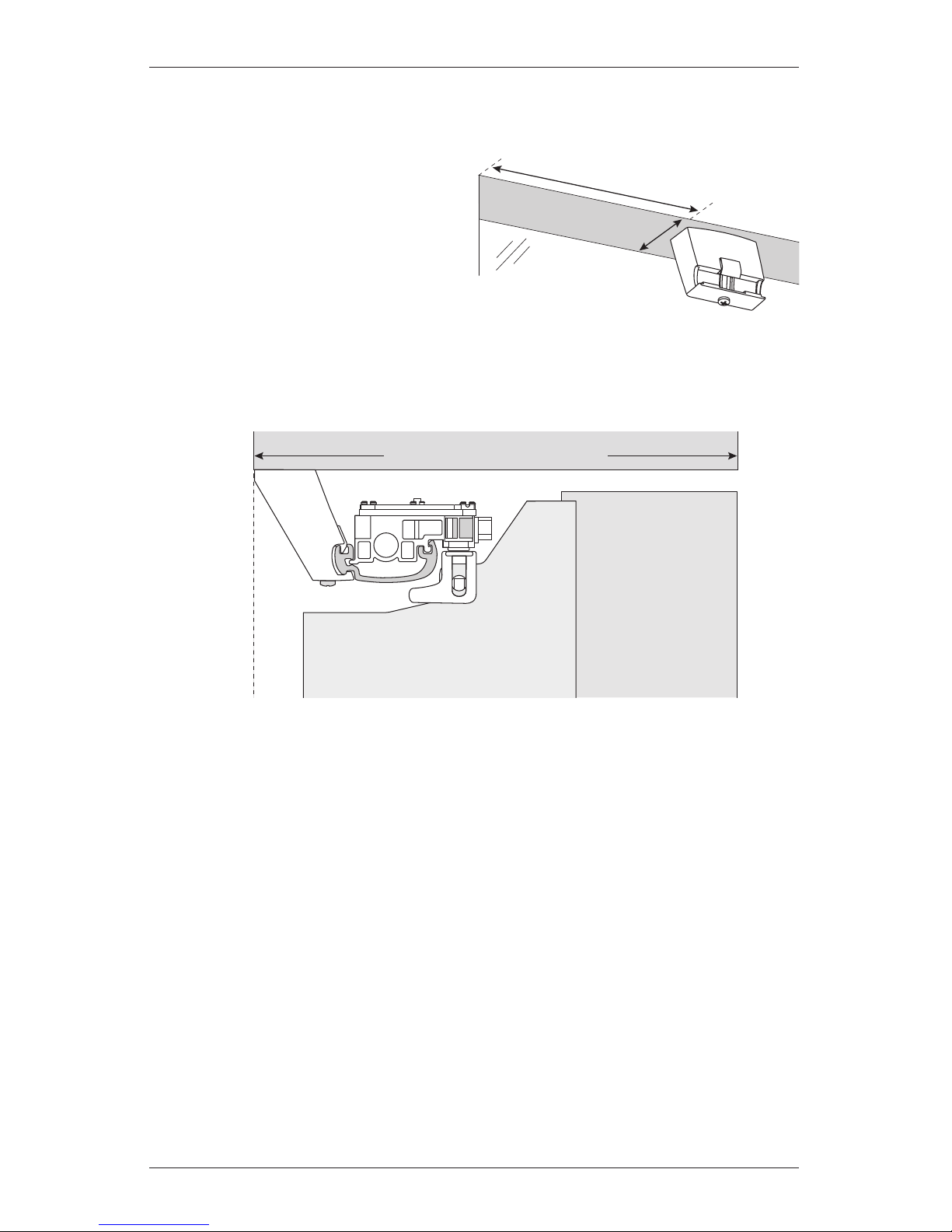
■ Mark where to drill holes for the screws.
IMPORTANT: The front edges of the brackets must align to each other.
➤ Align the outside edge of the end
brackets on your marks, then mark
each of the screw holes. Center
additional brackets on the marks to
mark their screw holes.
➤ The minimum mounting depth required is 1".
➤ To fully recess the fabric in the window casement, the mounting depth required is 6
1
/4".
See the illustration below.
Bracket Headrail
Stacked
Fabric
Vane
6
1
/4" Minimum Fully Recessed Depth
Inside Mount
Fully Recessed Mounting Depth
Window
Side
1" Minimum
5"
Page 8
INSTALLATION
6
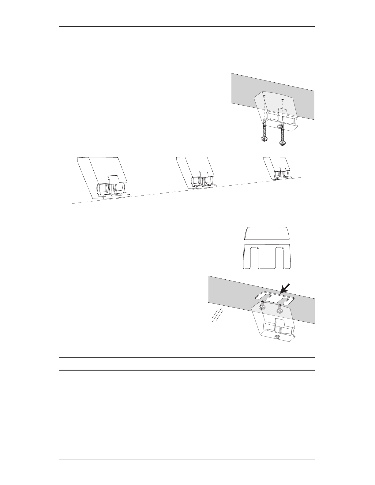
Mount the Brackets
■ Drill the screw holes using a 3/32" drill bit.
CAUTION: Use drywall anchors when mounting into
drywall.
■ Attach the installation brackets using the screws provided.
IMPORTANT: For proper operation, the headrail must
be mounted level. Use a laser level to check that the
installation brackets are level and aligned. Shim the
brackets if necessary. The brackets may also need to be
shimmed if the mounting surface is heavily textured.
To Shim the Brackets:
■ Snap off the top of the shim for use with inside/ceiling mount
brackets.
■ Use the shims, as needed, between the mounting
surface and the inside/ceiling mount brackets.
Use a laser level as reference.
■ To make further adjustments, you may add
or remove shims by loosening the installation
bracket screws.
Proceed to “Install the SofTrak™ Headrail” on page 12.
Level and
Aligned
Snap Off
Shim
Loosen
screws
to add or
remove shims.
Page 9
INSTALLATION
7
Mount the Installation Brackets — Outside Mount
If you are mounting on corner or bay windows, refer to “Bracket Locations — Corner and Bay
Windows” on page 11 for specific bracket locations. Return to this page after identifying the
bracket locations.
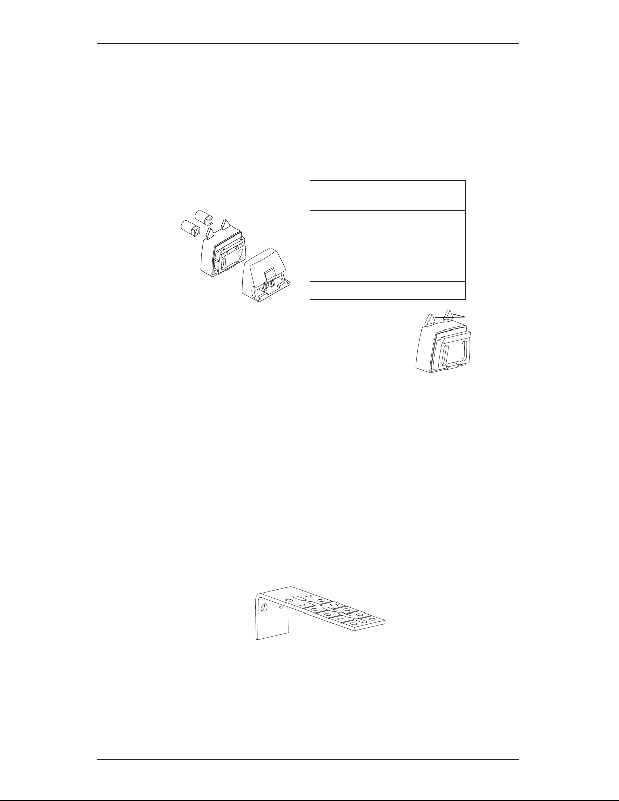
■ Your order will include the appropriate number of installation bracket assemblies. The
number of assemblies required varies with headrail width, as shown below.
IMPORTANT: The spacer blocks have tabs that prevent the
brackets from being mounted too close to the ceiling. If the sheer
will not be mounted at ceiling level, the tabs can be removed.
Adding Clearance
■ Use spacer blocks to add additional clearance. Spacer blocks add clearance in 1/
2
"
increments
.
➤ One spacer block is used with the faceplate for standard installation. Three additional
spacer blocks may be added for an extra 1
1
/2" clearance.
■ Use optional extension brackets to add more clearance.
➤ Extension brackets can provide up to 3
1
/2" clearance.
➤ Indentations are stamped into the extension brackets between each set of holes. Using
the indentations as a guide, you may cut off any unneeded length before mounting the
extension brackets. Each two-hole section is
1
/2" in length.
Headrail
Width
Bracket Assemblies
Required
Up to 40" 2
40
1
/8" – 70" 3
70
1
/8" – 96" 4
96
1
/8" – 155" 6
155
1
/8" – 192" 8
Removable
Tabs
Faceplate
Spacer
Block
Bushings
Outside Mount
Bracket Assembly
Extension
Bracket
Page 10
INSTALLATION
8
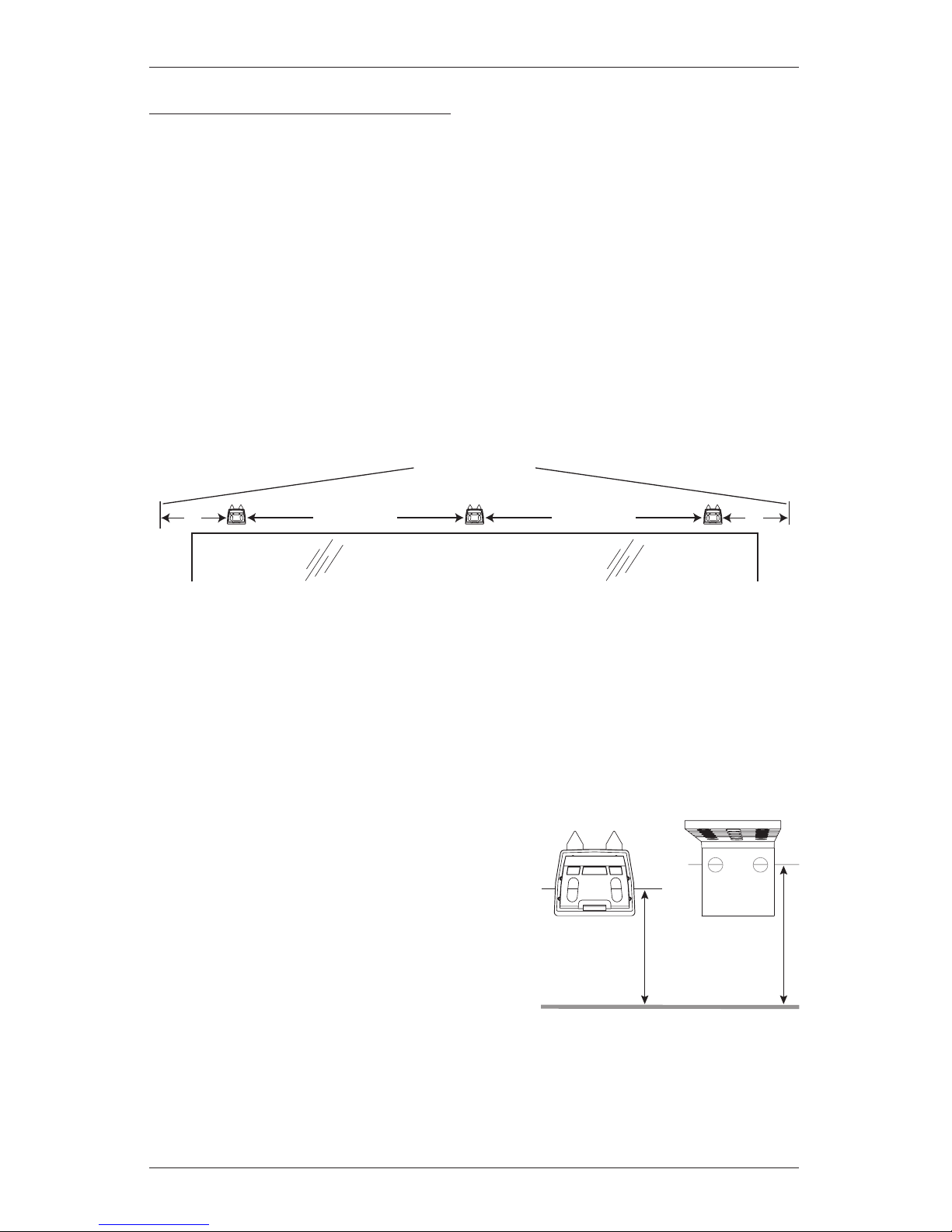
Measure and Mark Bracket Locations
■ Position the SofTrak
™
headrail over the window or door opening at the ordered height, found
on the headrail label. Use a pencil to lightly mark each end of the headrail.
➤ Alternatively, measure the width of the headrail and use that width to mark the headrail
end points over the opening.
IMPORTANT: Typically, split stack designs are centered over the opening. However, side
stack designs may be offset to one side if the fabric was intended to stack partially or
completely off the window or door opening. The intended stackback must be taken into
account when marking the headrail end points.
■ Mark 5" from each end of the headrail.
➤ If more than two installation brackets are required (see table on previous page), mark the
locations of additional bracket(s) spaced evenly between the two end brackets.
CAUTION: Installation brackets should be fastened into wood whenever possible. Use drywall
anchors when mounting into drywall. When attaching brackets into drywall, additional brackets
may be required to keep the headrail level after the fabric is attached.
■ Mark the bracket mounting height to allow proper floor clearance for the fabric when
attached to the headrail. This method provides a minimum of
1
/2" floor clearance.
➤ Locate the ordered height on the headrail label.
➤ Spacer Blocks: Measure the ordered height
minus
1
/4" from the floor surface. Mark this
height at each bracket location.
➤ Extension Brackets: Measure the ordered
height plus
1
/4" from the floor surface. Mark
this height at each bracket location.
IMPORTANT: Mount the screws at the
height indicated, or higher for additional
floor clearance. Be sure to clear all floor
obstructions such as carpet, vents, rugs, etc.
Floor Surface
Ordered
Height – 1/4"
Ordered
Height +
1
/4"
Spacer
Block
Extension
Bracket
Headrail End Marks
Window Opening
Space Evenly Space Evenly
5" 5"
Page 11

INSTALLATION
9
■ Mark where to drill holes for the installation screws.
➤ A minimum of 1
1
/8" flat vertical surface is required for spacer block installation and
1
3
/8" flat vertical surface is required for installation with extension brackets.
➤ Align the spacer blocks or extension brackets on your height marks.
➤ Align the outside edge of the end spacer blocks or extension brackets on your bracket
location marks, then mark each of the screw holes. Center any additional brackets on
the bracket location marks to mark their screw holes.
CAUTION: The rear of the spacer blocks or extension brackets must be flush against a flat
mounting surface. Do not mount blocks/brackets oncurved molding.
Mount the Spacer Blocks or Extension Brackets
■ Drill the screw holes using a 3/32" drill bit.
CAUTION: Use drywall anchors when mounting into drywall.
■ Attach the spacer blocks or extension brackets using the
screws provided.
➤ For the spacer block installation, first insert the square end
of the bushings into the slots in the spacer block. Insert the
screws through bushings.
IMPORTANT: With spacer blocks, place the screws in the
middle of the slots to make aligning the brackets easier.
Bushings
Bushings Inserted
5"
Headrail
End Mark
Headrail
End Mark
Screw
Height
Mark
Screw
Height
Mark
5"
Page 12

INSTALLATION
10
➤ For extension bracket installation, you may cut off any unneeded length (before
mounting) at indentations stamped into the brackets between each set of holes. Each
two-hole section is
1
/2" in length.
IMPORTANT: For proper operation, the SofTrak
™
headrail must be mounted level. Use
a laser level to check that the spacer blocks or extension brackets are level and aligned.
Shim the brackets if necessary. The brackets may also need to be shimmed if the mounting
surface is heavily textured.
To Shim the Brackets:
➤ Loosen the installation screws securing
the spacer block or extension bracket.
➤ Insert one or more shims between the
spacer block or extension bracket and
the mounting surface. Tighten the
installation screws.
Finish Bracket Assembly
Spacer Blocks
■ Add any additional spacer blocks required.
IMPORTANT: A maximum of four spacer blocks
can be used.
■ Hook the top of the faceplate to the front spacer
block and snap it into place.
Level and Aligned
Level and Aligned
Loosen
Mounting
Screws
Insert
Shim(s)
1
2
1
2
To Shim
Installation Bracket
To Shim
Extension Bracket
Faceplate
Page 13

INSTALLATION
11
Extension
Bracket
Cover
Extension
Bracket
Extension Bracket
Base Cover
Screws
Speed Nuts
Inside/Ceiling
Mount Bracket
Extension Brackets
■ Slide the base covers onto each extension bracket.
■ If necessary, use scissors to trim the flat bracket cover to length. Slide a cover onto
each bracket.
■ Attach inside/ceiling mount installation brackets using the screws and speed nuts provided.
Proceed to “Install the SofTrak™ Headrail” on page 12.
Bracket Locations — Corner and Bay Windows
■ Mount the spacer blocks or inside/ceiling mount brackets 8" from the corner.
MPORTANT: The ends of the headrails should be located 3"
from the corner.
➤ If additional spacer blocks or extension brackets are used,
the installation brackets must be moved further away from
the corner by the amount of added clearance.
➤ The ends of the headrail must be moved further away from
the corner by the same amount.
■ For bay windows, first center and mount the middle sheer headrail.
➤ Then mount the side sheers so that the abutting ends of the
headrails are the same distance from the bay window angle as
the ends of the middle sheer headrail.
8"
Brackets
5"
8"
5"
Motor
Motor
3"
Page 14

INSTALLATION
12
Install the SofTrak™ Headrail
■ Push up on the locking screws. This raises the
locking tab and makes the headrail easier to install.
■ The grooves on the back of the headrail are designed
to snap into the locking tab on the faceplate and
inside/ceiling mount bracket.
➤ Tilt the front of the headrail (the side with the
pinion clips) up so the top groove fits into the
locking tab on each installation bracket.
■ With the top groove in place on all brackets, tilt
the headrail down so the bottom groove fits into
the bottom tabs on the installation brackets.
■ Position/center the headrail and tighten the locking
screws until snug. Do not overtighten.
Inside Mount and Wall-To-Wall Outside Mount Installations
■ After the SofTrak headrail is installed into the installation brackets, check the clearance at
eachend and make any necessary adjustments.
IMPORTANT: The recommended amount of clearance varies according to the control end
and stack design, as shown below.
Tilt Down
Pinion
Clip
Tighten
Tilt Up
Locking
Tab
SofTrak
™
Headrail
Locking
Screw
Split Stack — Minimum Clearances*
5
/8"
Non-Motor End*
5
/
8
"
Right Stack Design — Minimum Clearances
7
/8"
Non-Motor End
5
/8"
Left Stack Design — Minimum Clearances
5
/8"
Non-Motor End
7
/8"
*Split Stack Design: Motor can be on the right or left, as ordered.
Motor End*
Motor End
Motor End
Page 15

INSTALLATION
13
Side-by-Side (Abutted) Installations (Simulated Split Stack)
A simulated split stack (the fabric opens in the
center) is two side stack systems installed with
the non-control ends side-by-side.
■ Adjust the SofTrak
™
headrails according
to the illustration for proper swivel arm
operation.
IMPORTANT: Be sure to measure the
spacing from end cap to end cap, not from
the swivel arms.
Non-Control
End Cap
Non-Control
End Cap
1
1
/2"
Swivel
Plates
Swivel
Arm
Swivel
Arm
Proper Installation
Simulated Split Stack
Page 16

INSTALLATION
14
Connect PowerView™ Components
Connect the Motor Assembly
■ Remove the orange cover from the drive
assembly, as shown to the right.
■ Align the pins with the holes in the drive
assembly, as shown below. Press the motor
up into the drive assembly until it clicks into
place.
IMPORTANT: If snapping the motor onto
the drive assembly seems difficult, grasp
the lead carrier and pull the carriers slightly
away from the motor, as shown at right.
The motor should now snap in easily.
■ If you remove the motor and need to reinstall it, check the drive assembly and make sure
the tilt gear aligns with the arrows.
➤ If necessary, use a screwdriver to turn the tilt gear until it is aligned.
Aligned Tilt Gear
Page 17

INSTALLATION
15
Connect the DC Power Supply
NOTE: When power is connected to the motor, a green LED inside the manual control button
housing will flash to indicate the sheer is ready.
NOTE: If you ordered an optional large DC power supply, refer to the instructions that came
with the unit.
■ Plug the power cable from the motor into the
extensioncable.
■ Plug the other end of the extension cable into the DC power
supply.
■ Secure the extension cable using the C-clips provided. Hide
the cable behind the fabric, making sure it does not impede
operation.
■ Space the C-clips approximately 15" apart along the
extension cable, as shown.
■ Plug the DC power supply into the power source.
WARNING: Keep cables and small parts
out of the reach of children. They can wrap cables
around their necks and STRANGLE. They can also
put small parts in their mouths and CHOKE.
WARNING: Electric shock and/or afire hazard may
occur if not properlyinstalled.
Test Headrail Operation
■ Use the manual control button on the motor to test the operation of the headrail.
1. Press and hold the manual control button for 6
seconds. The sheer will move slightly.
2. Release the manual control button. The sheer will
move to its fully open position to set the OPEN travel
limit, then move to the fully closed position to set
the CLOSE travel limit. Next, the vanes will rotate
counter-clockwise and then clockwise to set the
rotation limits. The sheer will move slightly one more
time to indicate that the travel limits have been set.
NOTE: There could be up to an 8 second pause between the vanes tilting from counterclockwise to clockwise.
■ Pressing the manual control button while the carriers are traversing or the pinion clips are
rotating will stop the action. The next button press will traverse the carriers or rotate the
pinion clips in the opposite direction.
15"
Maximum
DC
Power
Supply
C-Clip
Extension Cable
Power Cable
Motor
Assembly
Manual
Control
Button
Page 18

INSTALLATION
16
Attach the Fabric Panel(s)
Preparations
■ If necessary, use the manual control button to traverse the fabric carriers to
the fully stacked position.
■ Stand the tube on end on a clean surface with the valance at the top. Position
the tube at the end of the headrail where the fabric stacks.
■ If the tube is too long to stand on end, carefully and safely use a utility knife to
trim the tube to an appropriate length. Do not unroll the fabric until you begin
attaching the vanes to the pinion clips.
CAUTION: Be very careful when trimming the tube to avoid damaging the
fabric in any way.
■ Remove the protective wrapping from the fabric.
Attach the Vanes to the Pinion Clips
■ Unroll the fabric to gain enough slack to attach
the first vane to the pinion clip on the motor
drive assembly.
■ To attach vanes, insert the vane attachment
hole into the clip until it snaps securely in place.
➤ Pull down gently on each vane to ensure
that it is seated properly.
■ Unroll the fabric as you clip the rest of the
vanes into the pinion clips in sequence.
Be careful not to skip any pinion clips
orvanes.
Pinion
Clip
Installed
Vane
Tube
Fabric
Panel
STD R
Vane Attachment
Swivel
Plate
Swivel
Plate
Page 19

INSTALLATION
17
Attach Swivel Plates
■ The end treatments on both ends of the sheer attached with
swivel plates.
➤ Swivel plates are right- and left-specific, marked by
an R or an L. The swivel plates are packaged with the
product’s hardware.
■ Snap the rivet on the swivel plate into the
front clip on the control end cap. Swivel plates
attached on the left will have STD L stamped on
the top. Swivel plates attached on the right will
have STD R on the top.
■ Snap the rivet on the other swivel plate onto the swivel arm (side stack) or into the front clip
on the non-control end cap (split stack). Swivel plates attached on the right will have STD R
stamped on the top. Swivel plates attached on the left will have STD L on the top.
STD R STD L
Swivel Plate
Side Stack
Swivel Arm
Rivet
Swivel Plate
Split Stack
Rivet
Front Clip
Non-Control
End Cap
STD
R
STD
R
Rivet
STD L
Page 20

INSTALLATION
18
Attach the End Treatment(s) to the Swivel Plate(s)
■ Hold the end treatment near the swivel plate at a
height where the end vanes hang straight and the top
of the end treatment is approximately
1
/8" above the
top of the swivel plate.
■ Attach the end treatment by pressing it onto the
swivel plate.
■ If the end treatment is not hanging straight, separate
the swivel plate from the end treatment and reposition
it. Separate the swivel plate by pulling up on the end
treatment while holding the swivel plate in place.
■ Re-attach the end treatment. Repeat the adjustment
as necessary.
Swivel
Plate
Page 21

OPERATION
19
Using the PowerView™ Remote
First, activate the remote by pulling both plastic tabs from the back battery compartment.
IMPORTANT: If you have more than one remote, see “Adding Additional Remote(s) to the
PowerView
™
Shade Network” in the PowerView Motorization Remote Control Guide.
Joining a Sheer to a Group
IMPORTANT: The sheer will not operate using the remote until it has been joined to a group.
1. Press and hold ■ STOP for 4 seconds to put the remote in program mode. The lights on the
remote will flash to indicate it is in program mode.
2. Press the desired group number (1 – 6) on the remote. The backlight for the group number
will flash to show it is selected.
3. Press and hold the manual control button on the motor.
4. While continuing to press the manual button, press ▲ OPEN on the remote. The sheer will
move slightly to indicate it has joined the group. Release the manual control button.
5. Press and hold ■ STOP for 4 seconds to exit program mode. The lights will stop flashing.
Basic Operation
1. To wake up the remote, simply pick it up or press ■ STOP. The last group(s) selected will be
highlighted and active.
2. Press “all” or groups 1 – 6 to select the specific sheer(s) to operate. The group button(s) will
light to show they are selected.
a. Multiple group buttons may be selected at a time.
b. To deselect a group, press the group number again. The backlight for that group button will
go out.
3. Press ▼ CLOSE to traverse the selected sheer(s) closed, covering the opening.
Group 1
Group 2
OPEN
CLOSE
Group 3
Group 4
Group 5
Group 6
Favorite
(Sheer/vane position)
LEFT ARROW
Rotates vanes clockwise
RIGHT ARROW
Rotates vanes counter-clockwise
STOP
(Press and hold for
programming mode)
Page 22

OPERATION
20
4. Press ▲ OPEN to traverse the selected sheer(s) open, uncovering the opening.
5. Press ■ STOP to stop the sheer’s movement anywhere along its travel.
6. Press the right arrow to rotate the vanes counter-clockwise. (If the sheer is not already
drawn closed, pressing this button will close the sheer first and then rotate the vanes.)
7. Press the left arrow to rotate the vanes clockwise. (If the sheer is not already drawn closed,
pressing this button will close the sheer first and then rotate the vanes.)
8. Press ■ STOP to stop vane movement.
9. Press ♥ FAVORITE to send the selected sheer(s) to a preset position. Refer to the PowerView
™
Motorization Remote Control Guide on how to set a favorite position.
Further Operation and Programming Information
PowerView Pebble™ Remote and/or PowerView Surface Remote Operation
For information regarding operation and programming of the PowerView remote, refer to your
PowerView Motorization Remote Control Guide.
PowerView Scene Controller
For information regarding operation and programming of the PowerView Scene Controller, refer
to your PowerView Motorization Scene Controller Guide.
PowerView App Operation
The PowerView Hub is required for PowerView App operation. For information regarding setup
and operation using the PowerView App, refer to the online PowerView App Software Guide at
hunterdouglas.com/powerview/support.
Resetting the Sheer (If Necessary)
Basic Reset
The basic reset is used to set the sheer’s travel limits.
1. Press and hold the manual control button for 6 seconds. The sheer will move slightly.
2. Release the manual control button. The sheer will move to its fully open position to set the
OPEN travel limit, then move to the fully closed position to set the CLOSE travel limit. Next, the
vanes will rotate counter-clockwise and then clockwise to set the rotation limits. The sheer
will move slightly one more time to indicate that the travel limits have been set.
Resetting Shade Programming
This reset erases all programming from memory, including group assignments, preventing any
input device from operating the sheer. Its primary use is during installation to correct group and
network assignments. This reset does not affect travel limits.
1. Press and hold the manual control button for 12 seconds. The sheer will move slightly once
after 6 seconds, then again after 12 seconds. Release the button.
2. Refer to “Joining a Sheer to a Group” on page 19 to program the sheer to a group.
Page 23

OPERATION
21
Troubleshooting
If the sheer is not operating correctly:
■ First review the guide that came with your control device.
■ Refer to the following troubleshooting for specific solutions for your sheer.
If questions remain, please contact Hunter Douglas Consumer Support at
1-888-501-8364.
Problem
The headrail will not fit into the installation brackets.
Solution
Check that the installation brackets are level and aligned. Adjust and/or shim to
level, if necessary.
Check that the SofTrak
™
headrail is completely inserted into the installation
brackets. See “Install the SofTrak Headrail” on page12.
Problem
The sheer does not operate using the manual control button.
Solution
Unplug the power cable from the motor, then plug it back in. A green LED inside
the manual control button housing should flash to indicate the motor has power.
Check that the DC power supply is securely plugged into the wall outlet and that
the outlet has power.
Check that the DC power supply is securely connected to the barrel connector
from the motor. See “Connect the DC Power Supply” on page15.
Problem
The sheer is not responding to the PowerView™ remote.
Solution
IMPORTANT: A sheer will not operate until it is joined to a group.
Check that the correct group number is selected.
Check that the batteries in the remote are correctly inserted andarefresh.
The LEDs that backlight the remote should be bright when ■ STOP is pressed.
Problem
The fabric does not traverse, or does not traverse easily.
Solution
Check that the installation brackets are level, their front edges are aligned, and
there are no obstructions to the movement of the fabric (i.e., the cord is not
caught in thebrackets).
Problem
The fabric end treatment does not hang straight.
Solution
Separate the hook and loop strips. Reposition the end treatment on the swivel
plate. Repeat as necessary until the end treatment hangs straight. See “Attach
the End Treatment to the Swivel Plate” on page 18.
Page 24

OPERATION
22
Problem
The vanes do not rotate or they rotate incorrectly.
Solution
Check that the fabric is fully traversed.
Check that there are no obstructions to the movement of the vanes. Replace
protruding window cranks with T-cranks.
Problem
A vane does not hang correctly.
Solution
Check that the vane is completely inserted into the pinion clip. See “Attach the
Vanes to the Pinion Clips” on page 16.
Problem
A vane is out of alignment.
Solution
Manually turn the pinion clip to align it with the remaining pinion clips.
Problem
The end treatment arm does not swing around the end cap.
Solution
On inside mounts, check that there is clearance between the end of the headrail
and the window casement. See “Install the SofTrak
™
Headrail” on page12.
If the fabric stops before it has fully traversed, reset the system. See “Resetting
the Sheer” on page20.
Problem
The rail makes noise while traversing.
Solution
Check that the installation brackets are level and aligned. Also, check for
obstructions to the movement of the fabric.
From the top of the headrail, pull up
the plastic bead chain to check whether
it is loose. If so, use needlenose pliers
to remove the metal bead, then move
it down a notch and crimp it tightly
closed.
Swivel
Arm
Pull Up
Slack
Metal
Bead
Page 25

CARE
23
Removing the Fabric/ Motor/Headrail
Should you need to remove the fabric, motor, and/or headrail, refer to the following instructions.
Remove the Fabric from the Headrail
IMPORTANT: Make sure you have clean hands or wear disposable gloves when handling
Luminette
®
fabric. Select an area in the home where the fabric can be laid flat. To avoid
wrinkling the fabric, do not fold the fabric or drape it over furniture.
■ Traverse the fabric to the fully stacked position.
■ Detach both end treatments from the ends of the headrail, as shown.
■ Remove the fabric from each pinion clip. Hold the top of the vane near the polytab, and pull
down and to the left.
■ Lay the fabric flat on a clean surface with the vanes facing in the same direction.
■ If the original tube is available, gently roll the fabric onto it, making sure the fabric stays
straight. Do not roll the fabric too tightly.
Remove the Modular Motor
■ Unplug the motor’s power cable from the extension cable to
the DC power supply.
■ There are two methods for removing the motor shown on the
following page. Choose the one that works best for you.
Separate the end treatment
and swivel plate by pulling upward
on the end treatment while
holding the swivel plate in place.
Pinion
Clip
Removing the Fabric Vanes
Polytab
Vane
Page 26

CARE
24
■ Method 1: This method
works best when the fabric
has been removed from the
headrail.
Insert the screwdriver
into the slot on the drive
assembly. Twist about
one-fourth turn to release
the spring-latch, and pull
down gently on the motor
assembly to separate.
■ Method 2: This method
works best when fabric
is still installed on the
headrail.
Insert a hex key into the
side slot on the drive
assembly (either front or
back) to release the springlatch, then pull down gently
on the motor assembly to
separate.
Remove the Headrail
■ With the fabric and motor removed, loosen
and push firmly up on the locking screws of
the mounting brackets until the locking tab
lifts from the headrail.
■ Rotate the headrail down as shown, until
the headrail pops free from the bracket.
Locking Tab
Locking
Screw
Loosen and Push Up
SofTrak
™
Headrail
1
Tilt Down
2
Twist to
Release
Page 27

CARE
25
Cleaning Procedures
The fabric, header, and vane fabric are 100% polyester. They are resilient, anti-static, and dust
resistant. Periodic cleaning is recommended to help keep Luminette
®
Privacy Sheers looking
like new. For all cleaning applications, fabrics should remain hanging to minimize handling,
wrinkling, or puckering.
IMPORTANT: Disposable gloves should be worn when handling fabrics.
CAUTION: Keep all cleaning solutions away from the SofTrak
™
headrail system. Never immerse
the headrail.
Routine Cleaning
■ Use a feather duster for regular light dusting.
■ For more thorough dust removal, a hand-held vacuum with low suction may be used. When
vacuuming, avoid pulling or stretching the fabric.
➤ Start in the upper left corner and work across the fabric using short horizontal strokes
while steadying the fabric with your free hand. Each stroke should be approximately
the width of two to three vanes. Do not use long horizontal or vertical strokes, as these
actions will crease the fabric. Continue to the bottom of the fabric.
CAUTION: Do not use a brush attachment or rigorous vacuuming since either could distort
the fabric.
Electrostatic Cleaning
CAUTION: Do not use electrostatic cleaning devices on any Luminette product.
Spot-Cleaning
To reduce the potential for permanent staining, spots should be treated and cleaned as soon as
possible with a clothing stain pre-treatment solution.
■ Apply the pre-treatment solution to a clean, white cloth.
■ Support the fabric from behind using another clean, dry cloth.
Clean the spot using a gentle
blotting action. Avoid rubbing the fabric since any abrasive action may cause it to distort.
■ Let the area air dry.
■ After the area is dry, remove excess solution by blotting it with distilled or bottled water
applied to another clean cloth.
Deep Cleaning
For deep cleaning, both injection/extraction and ultrasonic cleaning methods are recommended.
CAUTION: Do not dry clean Luminette fabrics.
Page 28

CARE
26
Injection/Extraction Method
Professional injection/extraction cleaning injects a heated cleaning solution into the fabric and
extracts the dirty solution in the same motion. This process is done in the home.
■ Vacuum the fabric following the instructions under “Routine Cleaning” on the previous page,
prior to the injection/extraction cleaning.
■ Have your professional set and maintain their cleaning solution just below steaming.
■ Make sure stains are pre-treated to maximize the benefits of cleaning.
■ When cleaning the vanes from the back, use a 3" upholstery tool and start at the center of
the fabric. Clean one vane at a time from top to bottom working out toward the edge of the
fabric. Repeat for the other half of the fabric.
IMPORTANT: Both sides of each Luminette
®
room-darkening vane need to be cleaned.
This is not necessary on Luminette translucent vanes.
■ When cleaning the face fabric from the front, close the vanes to the right and use a 4"
upholstery tool. Start in the upper left corner, and using short, horizontal strokes (about the
width of three vanes), move across the fabric. Clean from the top to the bottom.
■ Allow the fabric to dry in the fully traversed position with the vanes opened.
■ Steam out any wrinkles.
Ultrasonic Method
Professional ultrasonic cleaning is a process in which the fabric is inserted into a tank of
cleaning solution and then subjected to high frequency vibrations. Dirt is loosened from the
fabric and carried away in the cleaning solution. This process is done outside the home.
■ Ensure the supplier’s ultrasonic tank is long enough to accommodate the full length of the
fabric without folding the fabric or vanes.
■ Ensure the fabrics are rolled onto a tube when being transported to and from the home. This
reduces the chance of wrinkling and damage.
■ Specify water that does not exceed 90° F throughout the process.
CAUTION: If water temperatures exceed 90° F, oxidation will damage the room-darkening
vanes of Luminette room-darkening fabrics.
■ Make sure stains are pre-treated to maximize the benefits of cleaning.
■ Hang fabrics immediately after cleaning with the vanes open and the loops evenly spaced.
Allow the fabric to drip dry completely.
Page 29

CARE
27
Wrinkle and Crease Removal
The steaming methods described below can be used to help minimize hard wrinkles or creases.
Hand Method
■ Rotate vanes to the fully opened position.
■ Apply warm distilled or bottled water to a clean, white cloth.
■ Support the fabric from behind using another clean, dry cloth.
■ Blot the wrinkle or creased area with the wet cloth.
■ Let the area air dry.
Steam Machine Method
■ Rotate vanes to the fully opened position.
■ Steam from the back side of the fabric whenever possible. Set the steamer to its lowest
possible setting, not to exceed 212° F (100° C).
■ The steaming unit should never directly touch the fabric. Hold the wand 2" to 3" away from
the fabric.
■ Use slow, continuous vertical movements. Begin at the top of the fabric and work your
way down.
■ Let the area air dry.
A Note About Textiles
As with all textiles, Luminette® fabrics are subject to some variations.
■ The fabric will change as its position changes.
■ Minor wrinkles, puckers, or other variations can appear and are inherent to this textile
product.
■ Such variations, like those just mentioned, are normal, acceptable quality.
Additional Product Enhancements
■ Luminette face fabric is available by the yard in widths up to 123", for creating such
accessories as top and side treatments, specialty shapes, table rounds, and bed skirts.
■ Add coordinating Silhouette
®
window shadings, Pirouette® window shadings, and Vignette®
Modern Roman Shades where applicable. The Whole House Solution
™
program lists
coordinating colors to make it easy to order these window fashions for installation in the
same room with Luminette fabrics. Contact your dealer for additional information.
Page 30

DECLARATIONS
28
U.S. Radio Frequency FCC Compliance
FCC ID information is located on a label affixed to the modular motor assembly.
This device complies with Part 15 of the FCC Rules. Operation is subject to the following two conditions:
(1) This device may not cause harmful interference, and
(2) This device must accept any interference received, including interference that may cause undesired
operation.
This equipment has been tested and found to comply with the limits for a Class B digital device, pursuant
to Part 15 of the FCC Rules. These limits are designed to provide reasonable protection against harmful
interference in a residential installation. This equipment generates, uses and can radiate radio frequency
energy and, if not installed and used in accordance with the instructions, may cause harmful interference
to radio communications. However, there is no guarantee that interference will not occur in a particular
installation. If this equipment does cause harmful interference to radio or television reception, which can be
determined by turning the equipment off and on, the user is encouraged to try to correct the interference by
one or more of the following measures:
• Reorient or relocate the receiving antenna.
• Increase the separation between the equipment and receiver.
• Connect the equipment into an outlet on a circuit different from that to which the receiver is connected.
• Consult the dealer or an experienced radio/TV technician for help.
Any changes or modifications not expressly approved by the party responsible for compliance could void the
user’s authority to operate the equipment.
Industry Canada
Under Industry Canada regulations, this radio transmitter may only operate using an antenna of a type
and maximum (or lesser) gain approved for the transmitter by Industry Canada. To reduce potential
radio interference to other users, the antenna type and its gain should be so chosen that the equivalent
isotropically radiated power (e.i.r.p.) is not more than that necessary for successful communication.
This device complies with Industry Canada licence-exempt RSS standard(s). Operation is subject to the
following two conditions: (1) this device may not cause interference, and (2) this device must accept any
interference, including interference that may cause undesired operation of the device.
Class B Digital Device Notice
This Class B digital apparatus complies with Canadian ICES-003, RSS-Gen and RSS-210.
CAN ICES-3 (B)/NMB-3(B)
European Conformity
We, the undersigned,
Hunter Douglas Window Fashions
One Duette Way, Broomfield, CO 80020, USA
Hunter Douglas Europe B.V.
Piekstraat 2, 3071 EL Rotterdam, The Netherlands
certify and declare under our sole responsibility that assembly PV3 conforms with the essential
requirements of the EMC directive 2004/108/EC and R&TTE directive 1999/5/EC.
A copy of the original declaration of conformity may be found at:
www.hunterdouglas.com/RFcertifications.
Page 31

Page 32

135103641 9/16
The Hunter Douglas® Lifetime Guarantee is an expression of our desire to provide a thoroughly satisfying
experience when selecting, purchasing and living with your window fashion products. If you are not thoroughly
satisfied, simply contact Hunter Douglas at (888) 501-8364 or visit hunterdouglas.com. In support of this policy
of consumer satisfaction, we offer our Lifetime Limited Warranty as described below.
NOTE: In no event shall Hunter Douglas or its licensed fabricators/distributors be liable or responsible for incidental
or consequential damages or for any other indirect damage, loss, cost or expense. Some states do not allow the exclusion or
limitation of incidental or consequential damages, so the above exclusion or limitation may not apply to you. This warranty
gives you specific legal rights, and you may also have other rights which vary from state to state.
Different warranty periods and terms apply for commercial products and applications.
Hunter Douglas (or its licensed fabricator/distributor) will repair or replace the
window fashion product or components found to be defective.
COVERED
BY A LIFETIME LIMITED WA RRANTY
• Hunter Douglas window fashion products are
covered for defects in materials, workmanship
or failure to operate for as long as the original
retail purchaser owns the product (unless shorter
periods are provided below).
• All internal mechanisms.
• Components and brackets.
• Fabric delamination.
• Operational cords for a full 7 years from the
date of purchase.
• Repairs and/or replacements will be made with
like or similar parts or products.
• Hunter Douglas motorization components are
covered for 5 years from the date of purchase.
NOT COVERED
BY A LIFETIME LIMITED WA RRANTY
• Any conditions caused by normal wear and tear.
• Abuse, accidents, misuse or alterations to the
product.
• Exposure to the elements (sun damage, wind,
water/moisture) and discoloration or fading
over time.
• Failure to follow our instructions with respect
to measurement, proper installation, cleaning
or maintenance.
• Shipping charges, cost of removal and reinstallation.
TO OBTAIN WARRANTY SERVICE
1. Contact your original dealer (place of purchase) for warranty assistance.
2. Visit hunterdouglas.com for additional warranty information, frequently asked questions and access to service locations.
3. Contact Hunter Douglas at (888) 501-8364 for technical support, certain parts free of charge, for assistance in obtaining
warranty service or for further explanation of our warranty.
 Loading...