

Page 1
100319
DecoFlex Wirefree RTS Wall Switch
Motorization
Radio Technology Somfy® (RTS) wall switches allow for up to a 65 ft. control range. The radio waves travel through walls
eliminating the need to point or aim the transmitter at the window covering. With a simple press of a button, users have the
ability to control all motorized window coverings individually and/or as a group with one control.
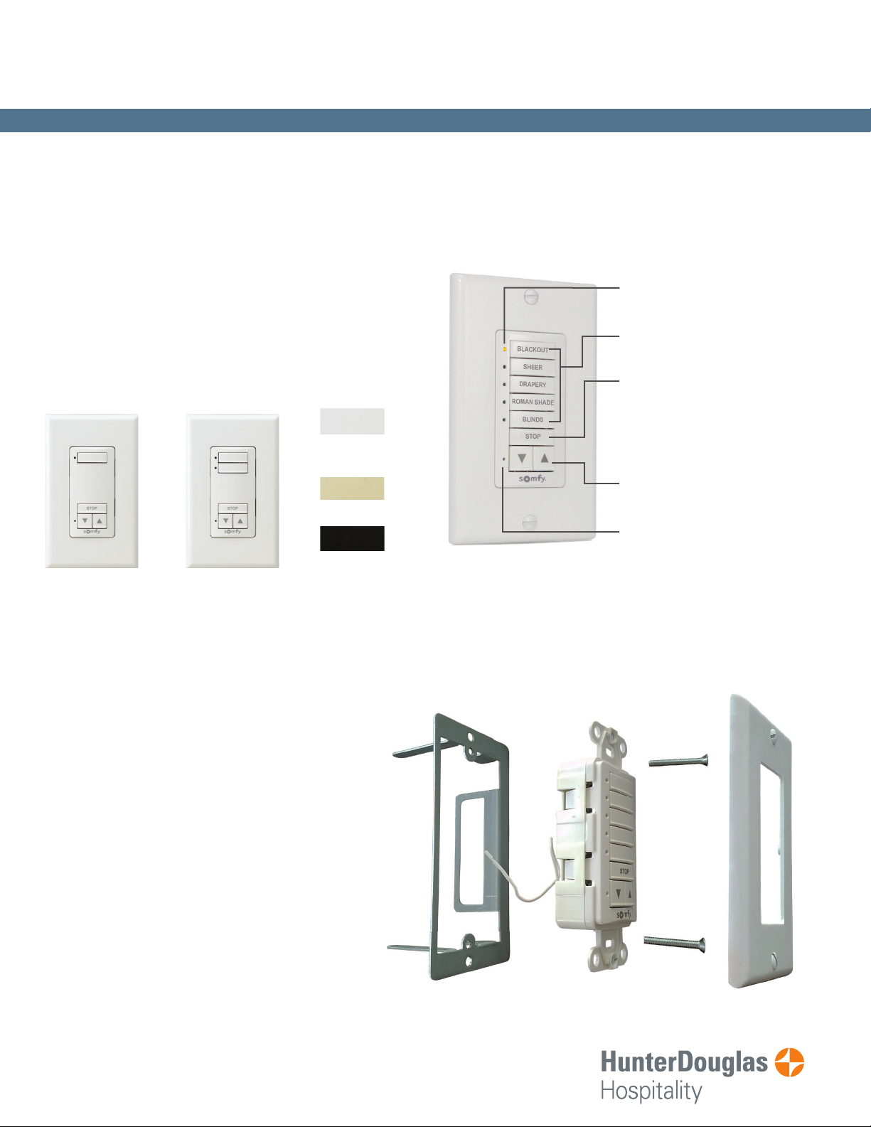
WIREFREE WALL SWITCH
• Recommended control for hospitality settings
• Available in 1 Channel, 2 Channel, and 5 Channel
• Channel buttons can be custom engraved for
easy organization
1 Channel
RTS Wall Switch
2 Channel
RTS Wall Switch
Available fi nishes:
White (shown)
Default color
unless specifi ed
Ivory
Black
INSTALLATION FEATURES
5 Channel RTS Wall Switch
LED indicator for each channel
Custom engraving on channel
buttons
“STOP” but ton stops the window
covering when it is in motion.
When the window covering is
stationary, the “STOP” button
brings it to the programmed
favorite position.
UP AND DOWN
Command Buttons
Programming Button (recessed)
RTS Wall Switch Installation Items
• Mounting bracket attaches to drywall
• No need for an electrical box (If used, it must be
plastic)
• Switch can be installed anywhere up to 65 ft
from the motor
NOTE:
For guest room installation, it is recommended
to mount the wall switch near the shade it will
control to insure guests are aware of motorization
operation.
Las Vegas • Chicago
800.229.5300
HDhospitality.com
Mounting
Bracket
DecoFlex
Switch
Wall plate
Screws
Page 2
DecoFlex Wirefree ™ RTS
Assembly/Installation/
Operating Instructions
Wall Switch Instructions
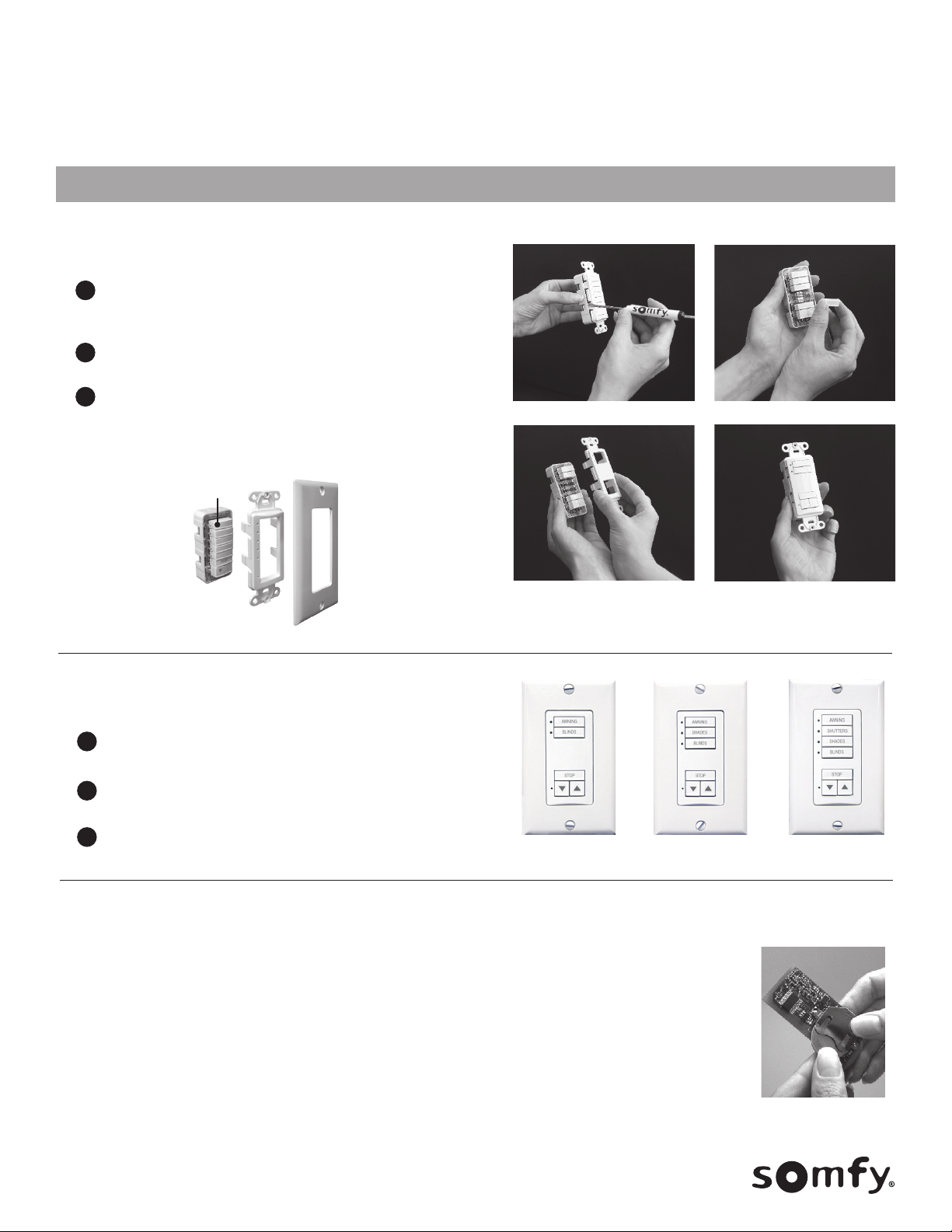
ASSEMBLY
ASSEMBLE MULTIPLE BUTTON SWITCHES
Begin with a standard (assembled) 1 or 5 control button DecoFlex switch. Using
1
a small flat blade screw driver, carefully separate the SWITCH BASE ASSEMBLY
from the FACEPLATE (as shown in figure 1).
Add or remove CONTROL BUTTONS (as required) from the SWITCH BASE ASSEMBLY
2
(as shown in figure 2). Be certain the SWITCH BASE ASSEMBLY remains intact.
Attach new multiple button face plate (as shown in figure 3 & 4).
3
5 Channel DecoFlex Wall Switch (Exploded view)
Removable Channel
Buttons
Figure 1.
(Ref: 1810813 +others)
Figure 2.
Switch Base
Assembly
8 Button
Faceplate
Wall Plate
Figure 3.
REPLACE STANDARD CONTROL BUTTONS
Using a small flat blade screw driver, carefully separate the SWITCH BASE
1
ASSEMBLY from the FACEPLATE (as shown in figure 1).
Replace standard (blank) or temporarily labeled CONTROL BUTTON(s) with
2
new engraved CONTROL BUTTON(s).
3
Attach new CONTROL BUTTON FACE PLATE (as shown in figure 3 & 4).
5 Button
Switch Assembly
6 Button
Switch Assembly
Battery Replacement:
The DecoFlex WireFree™ RTS switch is designed to provide years of maintenance-free performance. Should the battery become
discharged, the LED indicator lights will no longer function when the channel button is selected or an up, stop or down command is
activated. As a result, the radio signal will be reduced or not communicated to the RTS receiver or motor.
The battery can be easily replaced by exposing the SWITCH BASE ASSEMBLY board of the DecoFlex WireFree™ switch.
Simply slide the battery out of its holder and replace with a new 3V Lithium battery (type 2450) maintaining the correct polarity.
Figure 4.
7 Button
Switch Assembly
NOTE: Batteries should be disposed of properly according to local regulations.
© Copyright 9/2019 SOMFY SYSTEMS, INC.
P-0035HD
Page 3

DecoFlex Wirefree™ Wall Switch
INSTALLATION
Included is a special SOMFY low voltage device mounting bracket which attaches to drywall and eliminates the need for an electrical box.
The bracket can be used in two mounting type configurations:
Individual or “stand-alone” (1 switch) mounting configurations (shown below),
1
Or adjacent (pre-existing) Decora-style light switch (specific instructions available). This unique mounting bracket allows the necessary spacing for 2 adjacent switches
2
and a new “Double Gang” (2 Gang) wall plate to be installed (see photo 8) resulting in an aesthetically pleasing professional installation
NOTE: When following configuration 1, the mounting bracket is not designed to be used inconjunction with “old-work” or retrofit electrical boxes. (Please check local codes to determine if an
electrical box is required for your installation.) For increased radio performance, Somfy recommends the use of non-metallic electrical enclosures.
Tools required for installation:
Screw drivers (phillips and bladed), dry-wall saw, wall stud sensor, non-marring tape and pencil
Pick a location for the switch
1 2
and using a stud sensor,
locate a space between studs
and mark (for reference) with
removable tape or pencil.
Using a dry-wall saw (or similar)
3
begin to cut the drywall along the
traced outline. Do not cut hole larger
than outline as this may result in a
loose fitting bracket.
NOTE: Recommended hole dimensions
are (1 5/8” W x 3 7/16” L)
5
Position the DecoFlex switch into
mounting bracket aligning the
screw holes. Secure switch to
mounting bracket with screws
(provided).
Place the flat side of mounting
bracket (included) against
the wall, then trace the inside
shape of the bracket on wall
using a pencil or thin marker.
Insert bracket (as shown) into hole
4
and carefully bend bracket tabs 90
degrees behind the dry-wall to
ensure a tight secure fit.
Attach a Decora-style wall
6
plate over the switch to
complete installation.
OPERATION
Select the CONTROL BUTTON(s) programmed to a specific window covering(s). The adjacent LEDs will illuminate to
1
indicate the CONTROL BUTTON selected.
2
To raise the window covering(s), press the UP button. To lower the window covering(s), press the DOWN button.
To stop the window covering(s) at any time, simply press the STOP button.
3
For wall switches programmed to use group function, select a control button followed by an action
4
(default: Up, Stop and Down).
For detailed product operation information, refer to the product programming instructions.
NOTE: Switches require programming in order to operate as intended.
SAVE THESE INSTRUCTIONS FOR FUTURE REFERENCE
© Copyright 9/2019 SOMFY SYSTEMS, INC.
P-0035HD
LED
Indicators
RTS Programming
Button
Down
Button
Control
Buttons
Stop Button
Up Button
Page 4

DecoFlex WireFree™ RTS Switch
To ensure accuracy, please be sure this document has been printed as “Actual Size.”
Please verify using measurements provided.
Align the thin side of the template on existing electrical box (opposite stud side).
Align the mounting screw height with existing switch.
Trace the inside shape of the bracket on the wall.
Cut the drywall along the traced outline.
NOTE: Do not cut hole larger than outline as this may result in a loose fitting bracket.
*For complete installation information, please refer to the Programming/Operating/Assembly Installation Instructions.
1.67”
3.39”
Copyright Somfy Systems, Inc.1/2016
P-0024
 Loading...