

Page 1

ALPHA AWNING
SERIES
INSTALLATION AND MEASURING GUIDELINES
(INCLUDES THE SRS V2)
11/2019
Page 2

ALPHA AWNING SERIES INSTALLATION MANUALALPHA AWNING SERIES INSTALLATION MANUAL
Hunter Douglas Limited
Australia
PRODUCT MANUAL
INFORMATION
MEASURING AND INSTALLATION MANUAL ONLY.
PLEASE REFER TO YOUR ONLINE PORTAL FOR THE
UPDATED VERSION.
This Product Manual is only a guide to the measurement and installation.
Hunter Douglas Limited does not warrant the accuracy contained in this manual.
The information contained in this Product Manual is based on the measurement and installation
data known to us at the time of issue of the Product Manual and is therefore subject to changes
or amendments at any time without notice, and the right to change or amend is hereby expressly
reserved by Hunter Douglas Limited.
IMPORTANT
This Product Manual at all times remains the property of Hunter Douglas Limited.
Its contents are strictly confidential and may not be reprinted, copied, reproduced or multiplied in any
form. This Product Manual must be maintained in its original form and must be returned to Hunter
Douglas Limited upon first request. Hunter Douglas Limited is not responsible to you or anyone else
for any loss suffered in connection with the use of this product manual or any of the content.
© Copyright 2019 Hunter Douglas Limited [ABN 98 009 675 709] •18.016.085 •11/19
® Registered Trade Marks of Hunter Douglas Limited Somfy is a registered trade mark of SOMFY Pty Limited
DISCLAIMER ISSUED: NOVEMBER 2019
SAFETY & WARNING ADVICE
Page 2
Page 3

ALPHA AWNING SERIES INSTALLATION MANUAL
Safety and Warning Advice + General Advice .... 2
Fixings .......................................................... 3
Characteristics of Awning Fabrics ................... 4
Options and Limitations .................................. 5
Component Dimensions ................................. 6
INSTALLATION
Open Roller Installation ................................ 7
• Flow Chart .......................................................... 7
• Installation Instructions ........................................ 8
Headbox Installation ................................... 9
• Flow Chart ......................................................... 9
• Installation Instructions ..................................... 10
Installing the Roller Tube ........................... 12
• Flow Chart ....................................................... 12
• Installation Instructions ..................................... 13
ALPHA SRS V2 (Side Retention System)
Awning ....................................................... 22
• Exploded view diagram .................................... 22
• Flow Chart ....................................................... 23
• Installation Instructions
ALPHA Deep Channel Awning ................. 30
• Exploded view diagram .................................... 30
• Flow Chart ....................................................... 31
• Installation Instructions
ALPHA Pivot Arm Awning ......................... 34
• Exploded view diagram .................................... 34
• Flow Chart ....................................................... 35
• Installation Instructions
Pretensioning the Spring for Literise/Light Lift
Pretensioning the Spring for Literise/Light Lift .....38
Pretension Chart
..................................... 24
..................................... 32
..................................... 36
.......................................... 39
ALPHA Straight Drop Awning ................... 15
• Exploded view diagram .................................... 15
• Flow Chart ....................................................... 16
• Installation Instructions
ALPHA Cable Guide Awning .................... 18
• Exploded view diagram .................................... 18
• Flow Chart ....................................................... 19
• Installation Instructions
..................................... 17
..................................... 20
ALPHA Linking Option .............................. 40
• Exploded view diagram .................................... 40
• Flow Chart ....................................................... 41
• Installation Instructions
..................................... 42
USER INFORMATION
Operating Instructions .................................. 46
MEASURING INSTRUCTIONS
On Face Architrave ....................................... 46
Reveal and Top Fix (Side Fix) ........................ 48
Contents
Page 1
Page 4

ALPHA AWNING SERIES INSTALLATION MANUAL
SAFETY AND WARNING ADVICE
A minimum of 2 people are necessary for proper installation.
PLEASE NOTE:
Installation fixings will NOT be supplied with any of the ALPHA Awning Series.
Please refer to fixing section. Each installation should be assessed on a case by case scenario.
WARNING! – The brackets must be fixed solidly to a substantial surface. Hollow bricks or foam
products are not suitable. Brick veneer surfaces require at least 2 courses of brickwork above the
bracket and 2 courses below.
GENERAL ADVICE
The electrical data is shown on the label of electric operating awnings.
Tools: The following tools are required for installation:
• Level
• Battery Drill
• Screwdrivers
• Hammer Drill
• Drill Bits
• Spanner - 7mm (size of open end spanner for top aligner)
• Allen Key
Page 2
Page 5
ALPHA AWNING SERIES INSTALLATION MANUAL
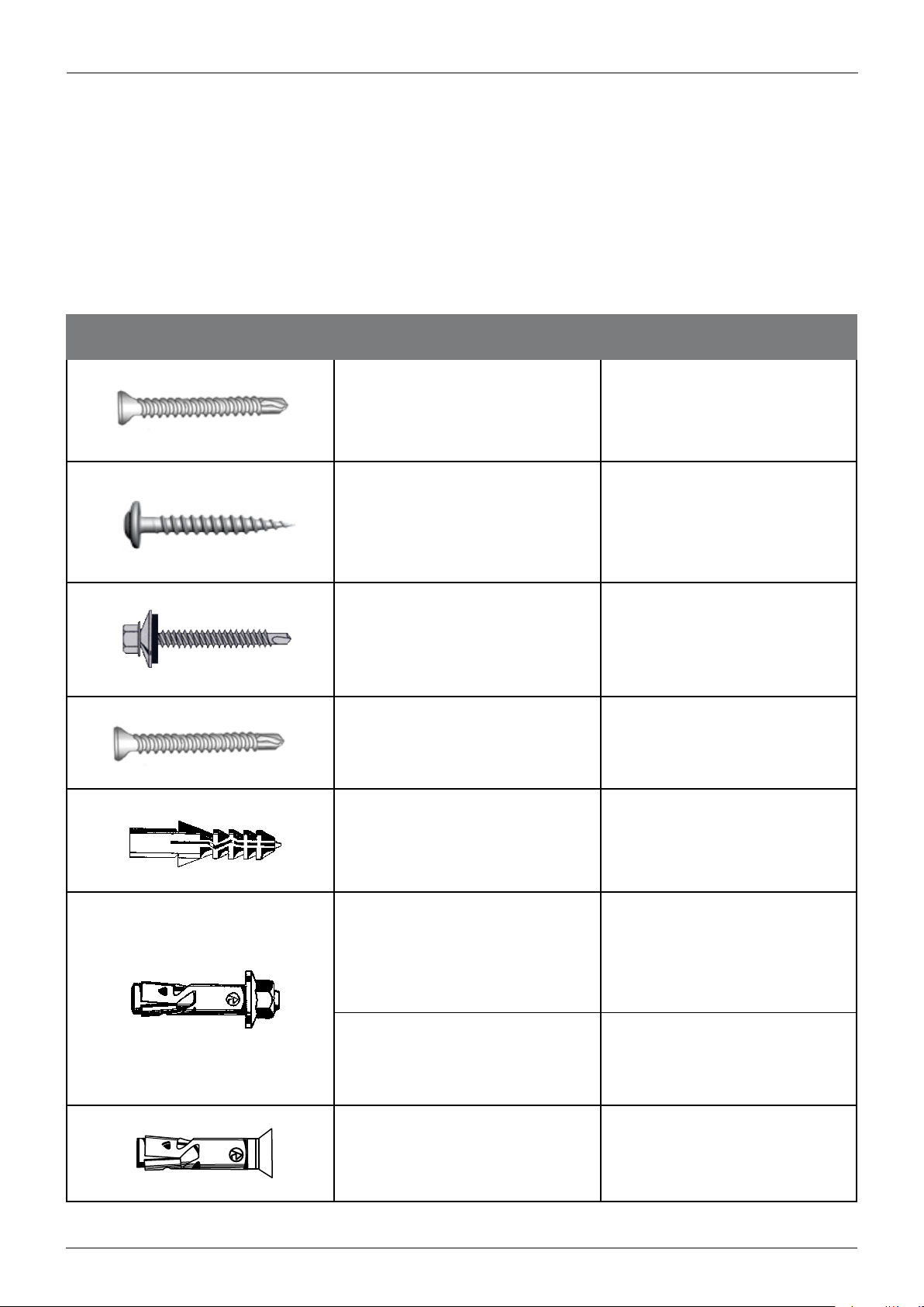
FIXINGS
Due to possible differences in specification, application and interpretation of results, users must
make their own evaluation of the product to determine the suitability of fixings and their intended
use.
ITEM TITLE DESCRIPTION
Counter Sunk (Zenith)
10g x 50mm
Available in Metal or Timber thread
Stainless
Waffer/Button Head (Buildex)
8g x 50mm
Available in Metal or Timber thread
Used to side fix channels.
Used to face fix channels.
Roofing & Cadding
Hex Head (Buildex)
12g x 50mm
Available in Metal or Timber thread
Counter Sunk (Zenith)
10g x 50mm
Available in Metal or Timber thread
Stainless
Ramplug/Green Plug (Ramset)
50mm Length
Dyna Bolt (Ramset)
6m x 30mm
Dyna Bolt (Ramset)
8mm x 50mm
Used to fix universal brackets.
Used to fix wire guide bottom
bracket.
Used to fit to brick or concrete
Used to face fix channels.
Used to fix universal brackets.
Counter Sunk (Ramset)
4.5mm x 30mm
Stainless
Page 3
Used to fix wire guide bottom
bracket.
Page 6

ALPHA AWNING SERIES INSTALLATION MANUAL
CHARACTERISTICS OF AWNING FABRICS
Some slight fabric curling may occur on fabric edge on large applications, whilst the following
characteristics are considered normal occurrences.
• Creasing (Figs. 1, 2)
• Puckering (Figs. 3, 4 & 5)
• Tension Induced Stretching (Figs. 6)
WARRANTY
Conditions apply. See www.hunterdouglas.com.au for Warranty document.
Page 4
Page 7

ALPHA AWNING SERIES INSTALLATION MANUAL
OPTIONS AND LIMITATIONS
CRANK GEAR MOTORISED INTERNAL CORD
OVERALL MAX WIDTH 5000mm 5000mm 3500mm
OVERALL MAX DROP 4000mm 4000mm 2900mm
OVERALL MIN DROP 300mm 300mm 300mm
MAX AREA 16 Sqm 16 Sqm 10 Sqm
MEASURING INSTRUCTIONS
Accurate measuring of the ALPHA Awning Series is vital for successful fitting and consequential
use. The product can be fitted on Face, Side or Ceiling fixing applications and can be operated by
crank, cord or motorised.
2mm deduction for Reveal Installs
Face Fit Supplied Overall Size
+/- 2mm Manufacturing Tolerance
Page 5
Page 8
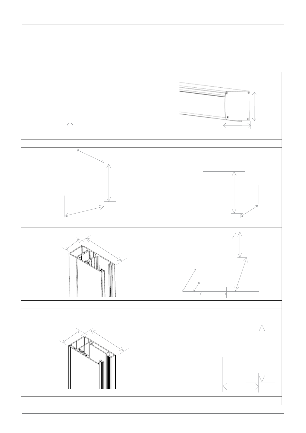
ALPHA AWNING SERIES INSTALLATION MANUAL
COMPONENT DIMENSIONS
125mm
14.7mm
130mm
CABLE GUIDE HEADBOX
68mm
100mm
50mm
100mm
UNIVERSAL INSTALLATION BRACKET BOTTOM RAIL
33.5mm
81mm
37mm
16mm
30mm
30mm
52mm
Page 6
23mm
DEEP CHANNEL BOTTOM CABLE BRACKET
37.5mm
73mm
ALPHA SRS V2 PIVOT ARM FRONT RAIL
50mm
33mm
Page 9
ALPHA AWNING SERIES INSTALLATION MANUAL
OPEN ROLLER INSTALLATION
STEP 1 - MARK FIXING HOLES FOR THE FIRST BRACKET
STEP 2 - DRILL FIXING HOLES
STEP 3 - INSTALL THE FIRST BRACKET
STEP 4 - MEASURE OVERALL WIDTH
STEP 5 - REPEAT STEPS 1,2 & 3 FOR
THE SECOND BRACKET
Page 7
Page 10
ALPHA AWNING SERIES INSTALLATION MANUAL
OPEN ROLLER INSTALLATION
STEP 1/2/3 - FACE FIT INSTALL
IDLE END DRIVE END
REVEAL FIT INSTALL
IDLE END DRIVE END
CEILING FIT INSTALL
IDLE END DRIVE END
Brackets will come pre-assembled with idle and drive end components attached. The orientation of these components
on the brackets will be determined by the fixing orientation specified on the order form. Example: Face/Reveal, Ceiling.
- Mark the fixing holes for the first bracket.
- Drill holes to suit the method of fixing determined by the substrate being fixed to.
- Screw the first bracket in place. Ensure the bracket is installed straight using a spirit level. If required, pack out
the bracket.
- Repeat process for the second bracket.
- Ensure both brackets are installed level and the distance apart is enough for the roller tube to be inserted. The
distance between the brackets should be the ordered overall measurement from outside of bracket to outside of
bracket.
Page 8
Page 11
ALPHA AWNING SERIES INSTALLATION MANUAL
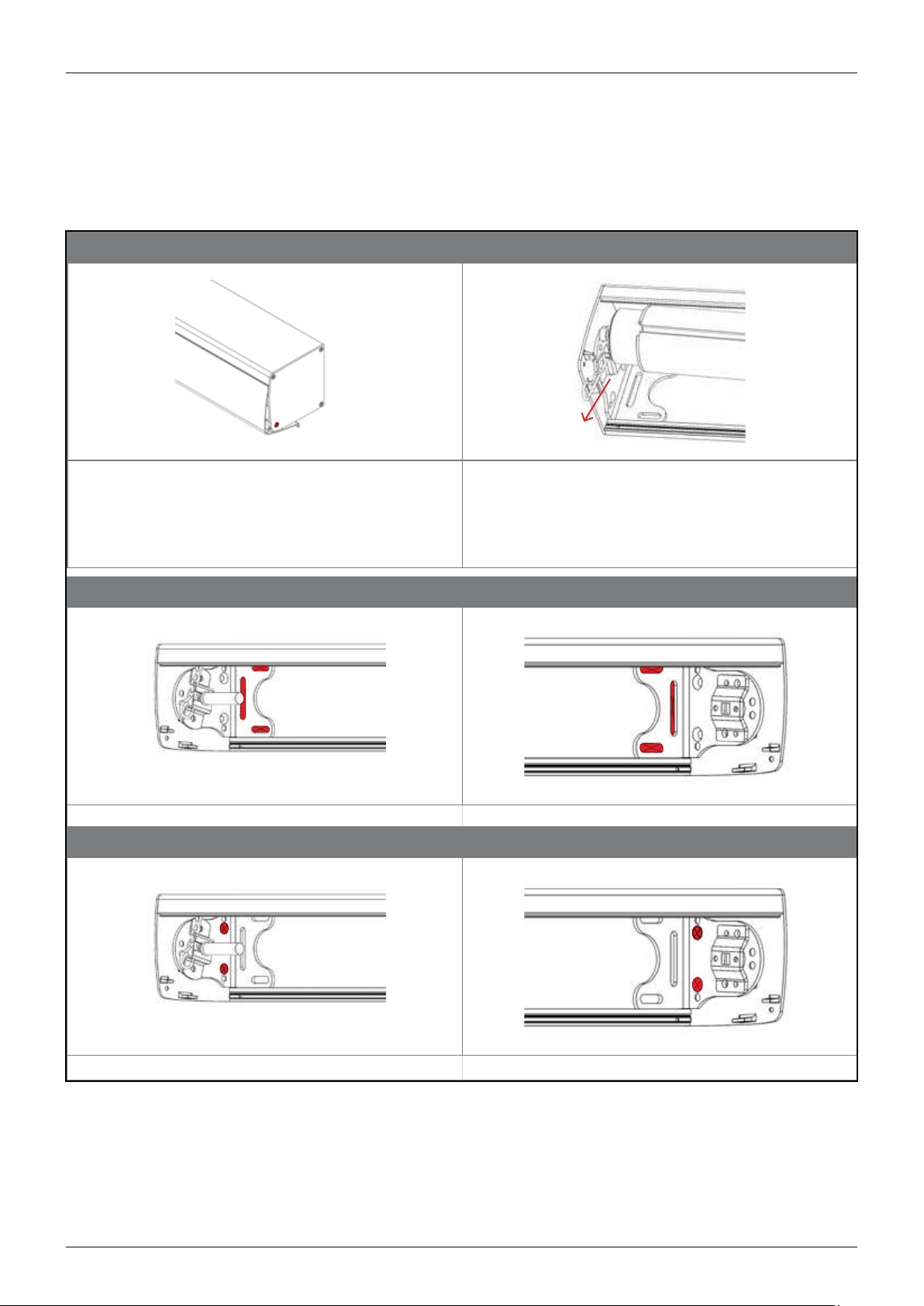
HEADBOX INSTALLATION
STEP 1 - OPEN THE HEADBOX
STEP 2 - REMOVE ROLLER TUBE
STEP 3 - MARK & PRE DRILL HEADBOX BACK PANEL
- MARK FIXING HOLES ON INSTALLATION SURFACE
- DRILL FIXING HOLES ON INSTALLATION SURFACE
- INSTALL HEADBOX THROUGH BRACKETS
ACCESSORIES
INSTALLATION SPREADER PLATE
PLEASE REFER TO RELEVANT SECTION FOR INSTRUCTIONS
Page 9
Page 12
ALPHA AWNING SERIES INSTALLATION MANUAL
HEADBOX INSTALL
STEP 1 - OPEN THE HEADBOX STEP 2 - REMOVE ROLLER TUBE
Open the headbox front cover by unscrewing the bottom
screw on the headbox end cap. Repeat on opposite side.
NOTE: For reveal fit the screw is no longer required.
STEPS 3 - FACE FIT
IDLE END DRIVE END
STEPS 3 - REVEAL FIT INSTALL
Pull out the idle end locking pin and remove the roller
tube idle end first.
Page 10
IDLE END DRIVE END
Page 13
ALPHA AWNING SERIES INSTALLATION MANUAL
STEPS 3 - CEILING FIT INSTALL
IDLE END DRIVE END
Mark and drill the head box back plate where the fixings will go.
NOTE: Always secure the headbox back panel through the installation brackets or spreader plate!
• After determining the exact position of the headbox you can fasten the brackets and headbox on the installation
surface.
• Mark the fixing holes for the first bracket.
• Drill holes to suit the method of fixing determined by the substrate being fixed to.
• Secure installation screw in bracket to hold one side of head box.
• Repeat the process for the opposite bracket and ensure that the head box is straight using a spirit level.
NOTE: If required pack out the headbox.
• Once satisfied the headbox is level, secure remaining fixing points.
NOTE: For awnings over 3500mm wide, add an additional fixing point through the centre of the headbox back panel.
E.g 3500mm wide secure at 1750mm.
ACCESSORIES REVEAL FIT - HEADBOX COVER INSTALL
D4.5mm
6.0mm
D4.5mm
45mm
6.0mm
SPREADER PLATE OPEN HEADBOX CLOSED HEADBOX
If there is no substantial fixing point at the ends
of the headbox, a Spreader Plate can be added.
This allows 250mm of flexibility for installation
points at each end of the awning. If a spreader
plate is ordered, this will come preassembled to
A 4.5mm hole needs to be drilled in the headbox cover in
REVEAL applications. Location of hole, refer to diagram above.
the bracket inside the headbox determined by the
installation type specified. Secure through Fixing
points highlighted in the image.
Page 11
Page 14
ALPHA AWNING SERIES INSTALLATION MANUAL
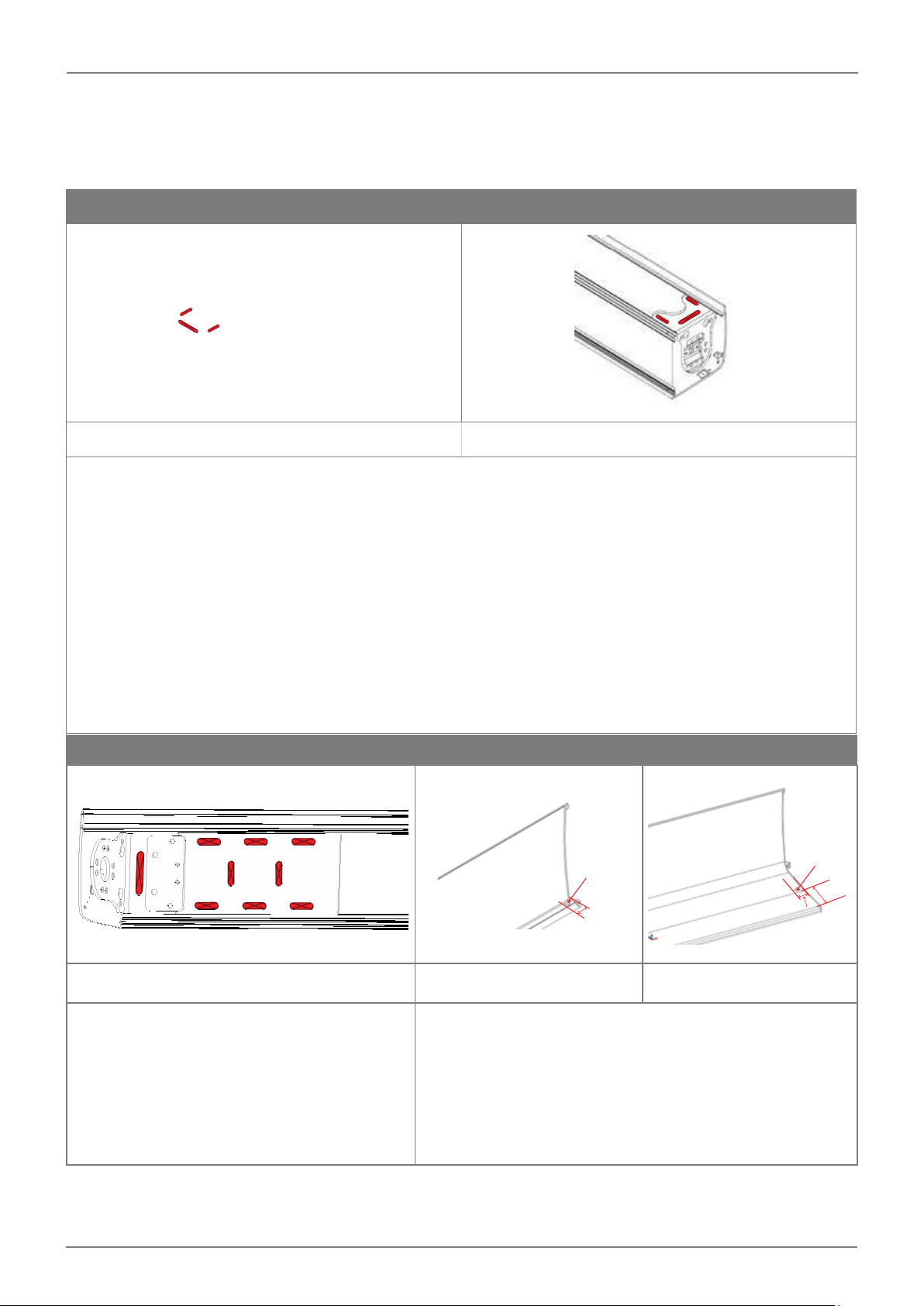
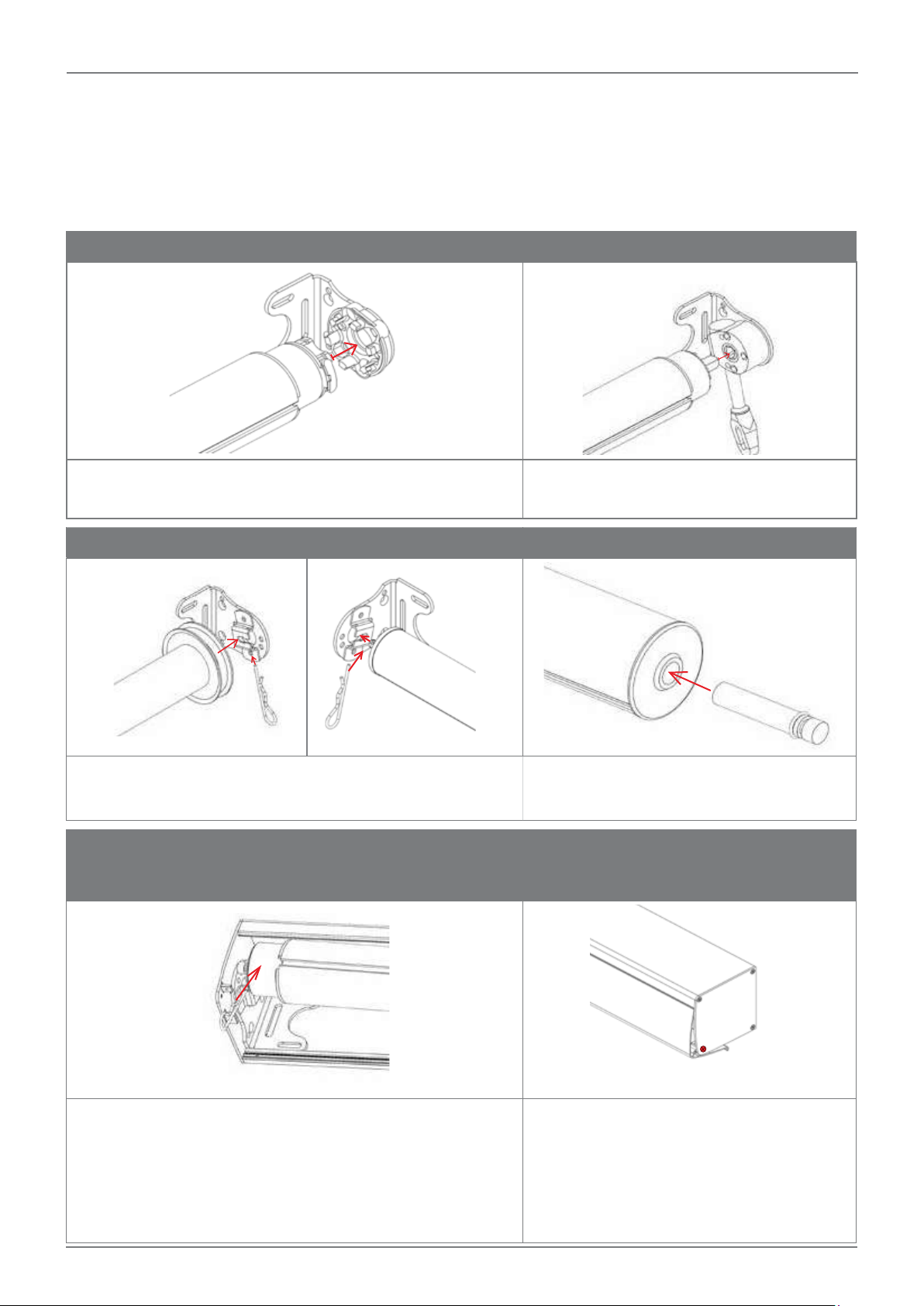
INSTALLING THE ROLLER TUBE
STEP 1 - INSTALL THE DRIVE END
STEP 2 - INSTALL THE IDLE END
OPTIONAL: STEP 3 - ATTACH THE HEADBOX FRONT COVER
OPTIONAL: INTERNAL TAPE WINCH INSTALLATION
INSTRUCTIONS
Page 12
Page 15
ALPHA AWNING SERIES INSTALLATION MANUAL
INSTALLING THE ROLLER TUBE
STEP 1 i - MOTORISED STEP 1 ii - CRANK
Motorised – Insert motor into motor bracket then secure using
motor clip
STEP 1 iii - INTERNAL TAPE WINCH
Internal Tape Winch – Insert pin into spring plate and use locking
pin to secure.
STEP 2 B - INSTALL THE ROLLER
Crank – insert crank pin into crank gear
STEP 2 A - INSERT PIVOT PIN
Insert Pivot Pin into idle end on tube.
OPTIONAL: STEP 3 - ATTACH THE
HEADBOX FRONT COVER
Lift Roller over the installation bracket and down so pivot pin sits
inside the pivot plate. Insert idle locking pin to secure roller.
*Operate the awning a couple of times to ensure tracking and correct operation of the awning.
Page 13
Once satisfied, reattach the headbox front
cover.
Page 16
ALPHA SERIES INSTALLATION MANUAL
ALPHA AWNING SERIES INSTALLATION MANUAL
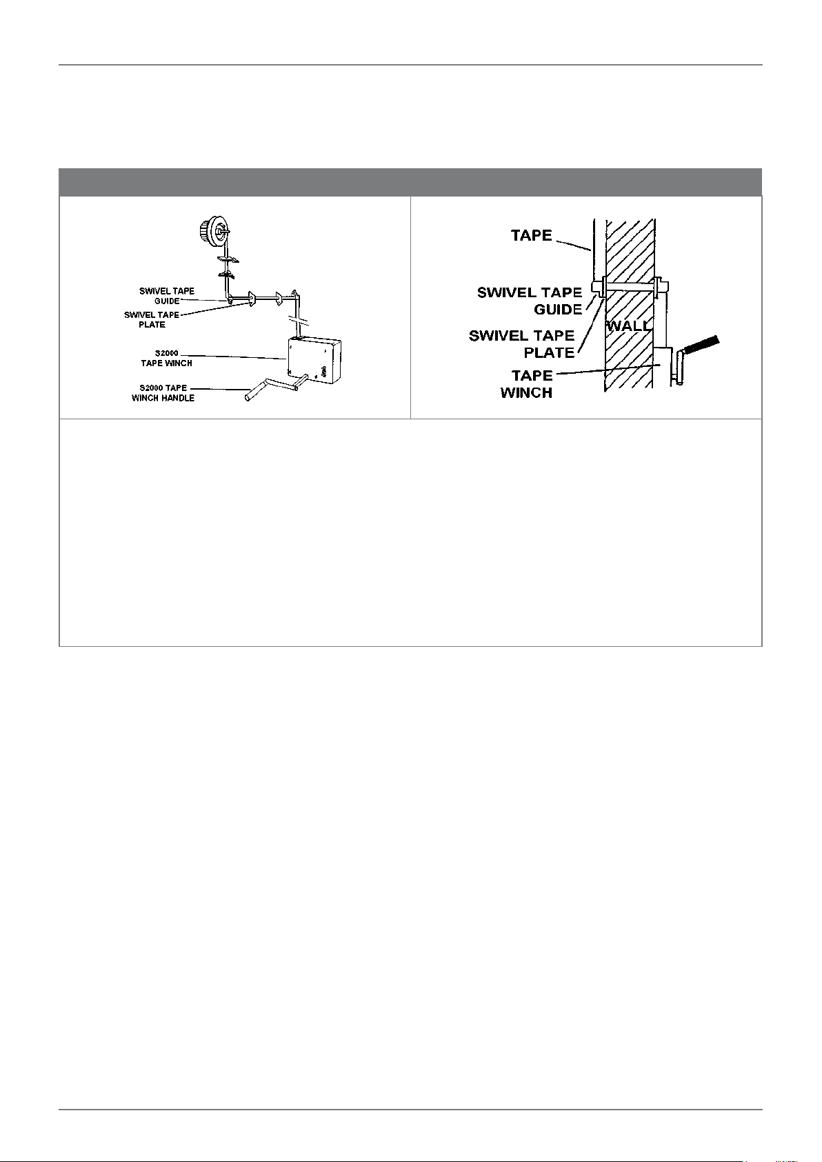
INTERNAL TAPE WINCH INSTALL INSTRUCTIONS
Fitting Internal Tape Winch
- Unscrew the cover of the internal tape winch and note the direction in which the tape runs off the spool.
- Remove the tape supplied with the winch.
- Thread the tape from the awning tape spool through the two swivel tape guides. Attach swivel tape guides to the
internal and external walls. Lower the awning.
- Thread the end of the tape through the slot on the tape winch spool. Cut the tape so that only 1 - 2 windings will
remain on the spool. Tie a secure knot in the end. Wind the excess tape on to the spool. Replace the spool in the
winch ensuring that the tape winds off in the correct direction. Screw cover back on to winch.
- Drill four (4) holes in the wall for the winch and fit rawl plugs supplied or use the fastener appropriate for the
installation. At least two of the screws should be set into an architrave or stud. All four screws must be used. If
necessary add packing behind the winch if attaching to an uneven surface.
- Test the awning to see if it functions properly.
Page 14
Page 17

ALPHA AWNING SERIES INSTALLATION MANUAL
ALPHA STRAIGHT DROP
2
5
6
3
1
7
8
19
9
4
17
16
12
13
14
15
18
11
10
No Part Description
1 46.608.XXX HEADBOX END CAP LH & RH
2 46.005.XXX HEADBOX BACK PLATE
46.012.XXX*
3
46.013.XXX*
4 46.019.XXX 100MM UNIVERSAL BRACKET
5 46.002.XXX PIVOT PIN & PLATE
46.506.000
6
44.210.000
46.507.000
42.180.049
46.522.500
7
46.522.700
46.521.500
46.521.700
42.603.855
44.209.000
8
46.504.000
46.505.000 6.
*000 - MILL, 100 -SILVER PEARL, 134-MOMBASA, 734-YALUMBA, 737-CHARDONNAY, 810-THUNDERCLOUD, 850-WHITE SATIN
Page 15
R HEADBOX FRONT COVER (CLOSED)
R HEADBOX FRONT COVER (OPEN)
60MM IDLE END
70MM IDLER WITH HOLE
78MM IDLE END
60MM TUBE
70MM TUBE 5MT
70MM TUBE 7MT
78MM TUBE 5MT
78MM TUBE 7MT
60MM DRIVE END - SMALL
70MM DRIVE END
78MM CRANK DRIVE END
60MM DRIVE END - 13MM SHAFT
No Part Description
9 46.502.XXX 9:1 GEAR
10 46.524.000 PLAIN BOTTOM RAIL END CAP
11 46.517.000 R BOTTOM RAIL LOCKING PIN
12 46.500.000 HOLD DOWN CLIP
13 42.236.000 BUCKLE FOR HOLD DOWN STRAP
14 42.230.000 RUA STRAP
15 42.204.000 BREECHING STAPLE
16 46.011.XXX R BOTTOM RAIL
17
18
19
82.29X.XXX
44.XXX.XXX
44.132.000
42.421.855
42.198.000
42.421.855
CANVAS FABRIC
EXTERNAL SCREEN FABRIC
4.2MM ES SOLID SPLINE
6MM SPLINE
3.5MM HARD SPLINE
6MM SPLINE
Page 18

ALPHA AWNING SERIES INSTALLATION MANUAL
ALPHA STRAIGHT DROP AWNING INSTALLATION
STEP 1
i - OPEN ROLLER INSTALL (pg7)
ii - HEADBOX INSTALL (pg9)
STEP 2
INSTALL ROLLER TUBE (pg12)
STEP 3
i - INSTALL HOLD DOWN STRAPS (pg17)
ii - INSTALL LOCKING BOLTS (pg17)
Page 16
Page 19

ALPHA AWNING SERIES INSTALLATION MANUAL
ALPHA STRAIGHT DROP AWNING INSTALLATION
STEP 1 - INSTALL HEADBOX OR OPEN ROLLER
Refer to the following sections for instructions
i - open roller install (pg7)
ii - headbox install (pg9)
STEP 3 - INSTALL HOLD DOWN STRAPS
In order to protect the hold down clips they will be supplied uninstalled from the bottom rail.
- Remove Bottom Rail end cap
- Insert ALL Hold down clips with strap, buckle and dog clip attached.
- Lower awning to desired fixing height.
- Slide hold down clips and straps to desired hold down locations.
- Reattach bottom rail end cap.
- Fix breeching staple to floor or wall surface under hold down straps.
- Use dog clip to attach hold down to breeching staple.
STEP 2 - INSTALL THE ROLLER TUBE
refer to installing the roller section (pg12)
STEP 3 ii - INSTALL LOCKING BOLTS TO
REVEAL POST
The locking bolts will be supplied pre-installed in the
bottom rail
Secure to Reveal post
- Lower awning to desired fixing height.
- Slide locking bolts out to desired fixing location
- Line up locking bolts with the posts and ensure the
bottom rail is level.
- Mark fixing holes on post and drill using a 12mm drill
bit.
- Slide locking bolts into the hole and apply tension to
ensure a level installation.
- Holes can be drilled at a variety of different stopping
locations along the post dependent on consumer
requirements
STEP 3 iii - INSTALL LOCKING BOLTS USING
BREECHING STAPLE
The locking bolts will be supplied pre-installed in the
bottom rail
Secure using Breeching Staple
- Lower awning to desired fixing height.
- Slide locking bolts out to desired fixing location
- Place breeching staple to floor or wall surface to
ensure the locking bolt can be secured under the
breeching staple.
- Ensure the bottom rail is level. If not, pack out
breeching staple to ensure bottom rail will be perfectly
horizontal when secured.
- Fix breeching staple to floor or wall surface.
- Slide locking bolts into the hole and apply tension to
ensure a level installation.
Page 17
Page 20

ALPHA AWNING SERIES INSTALLATION MANUAL
ALPHA CABLE GUIDE AWNING
2
1
5
6
No Part Description
1 46.608.XXX HEADBOX END CAP LH & RH
2 46.005.XXX HEADBOX BACK PLATE
46.012.XXX*
3
46.013.XXX*
4 46.019.XXX 100MM UNIVERSAL BRACKET
5 46.002.XXX PIVOT PIN & PLATE
6
46.506.000
44.210.000
46.507.000
42.180.049
7
46.522.500
46.522.700
46.521.500
46.521.700
8
42.603.855
44.209.000
46.504.000
46.505.000
R HEADBOX FRONT COVER (CLOSED)
R HEADBOX FRONT COVER (OPEN)
60MM IDLE END
70MM IDLE END
78MM IDLE END
60MM TUBE
70MM TUBE 5MT
70MM TUBE 7MT
78MM TUBE 5MT
78MM TUBE 7MT
60MM DRIVE END - SMALL
70MM DRIVE END
78MM CRANK DRIVE END
60MM DRIVE END - 13MM SHAFT
3
7
8
16
9
12
4
14
11
15
13
10
18
No Part Description
9 46.502.XXX 9:1 GEAR
10 46.524.000 PLAIN BOTTOM RAIL END CAP
11 46.108.063 CG CABLE GUIDE SET
12 46.530.063 EXTENSION PLATE
13 46.011.XXX R BOTTOM RAIL
82.29X.XXX
14
44.XXX.XXX
44.132.000
15
42.421.855
42.198.000
16
42.421.855
17 46.520.000 HEADBOX REVEAL CLIP
18 46.517.000 R BOTTOM RAIL LOCKING PIN
CANVAS FABRIC
EXTERNAL SCREEN FABRIC
4.2MM ES SOLID SPLINE
6MM SPLINE
3.5MM HARD SPLINE
6MM SPLINE
Page 18
*000 - MILL, 100 -SILVER PEARL, 134-MOMBASA, 734-YALUMBA, 737-CHARDONNAY, 810-THUNDERCLOUD, 850-WHITE SATIN
Page 21

ALPHA AWNING SERIES INSTALLATION MANUAL
ALPHA CABLE GUIDE AWNING INSTALLATION
STEP 1
i - OPEN ROLLER INSTALL (pg7)
ii - HEADBOX INSTALL (pg9)
STEP 2 - INSTALL THE BOTTOM CABLE BRACKET
STEP 3 - INSTALL THE CABLE & FLOATING END CAP
STEP 4 - APPLY TENSION TO THE WIRE
STEP 5 - INSTALL THE ROLLER TUBE (pg12)
STEP 6 - CONNECT FLOATING END CAP TO BOTTOM RAIL
ACCESSORIES
NOTE: OPTIONAL EXTRAS INCLUDE:
HOLD DOWN CLIPS (pg21)
SLIDING BOLT (pg21)
PLEASE REFER TO RELEVANT SECTION FOR INSTRUCTIONS
Page 19
Page 22

ALPHA AWNING SERIES INSTALLATION MANUAL
ALPHA CABLE GUIDE AWNING INSTALLATION
STEP 1 - INSTALL HEADBOX OR OPEN ROLLER
Reveal” Install
through this location
Top Cable Bracket
Refer to the following sections for instructions
i - open roller install (pg7)
ii - headbox install (pg9)
NOTE: cable guide installation bracket will come with top
cable bracket pre attached
STEP 2 B - INSTALL THE BOTTOM CABLE
BRACKET
STEP 2 A - PREPARE THE BOTTOM CABLE
BRACKET
Eclip
Barrel
Bottom Cable Bracket
Tension Pin
Use a string line or sprit level from the edge of the blind
bracket or side of the headbox to determine the correct
location of the wire guide bottom bracket.
NOTE: The bottom bracket is universal and can be used
for wall, floor or reveal mounting.
- Remove the Eclip from the barrel using screw driver or
pointy nose plyers.
- unscrew the bottom tension pin from the bottom of the
wire.
- remove the barrel from the bracket.
STEP 2 C - SECURE THE BARREL
Barrel Lip
Once bracket is fixed to ground/wall, slide in barrel, ensure
Place the bottom cable bracket on the location mark and
fix into place with the appropriate fixings.
the “lip” of barrel is facing towards the awning fabric.
Insert the Eclip around the “lip” of the barrel to ensure
the barrel is secure.
STEP 3 A - ATTACH WIRE TO BOTTOM BRACKET STEP 3 B - ATTACH FLOATING END CAP TO WIRE
Lock Nut
Insert the Tension pin through the barrel and screw to the
bottom of the wire, turn 3 - 4 times to secure.
Page 20
Unwind the wire and feed floating end cap onto the wire.
Page 23

ALPHA AWNING SERIES INSTALLATION MANUAL
STEP 4 A - ATTACH WIRE TO TOP CABLE BRACKET STEP 4 B - APPLY TENSION TO THE WIRE
Feed wire through the top cable brackets. Pull the wire
tight. Lock off with a 4mm Allen key. Ensure the grub
screw is secured tightly.
STEP 5 - INSTALL THE ROLLER TUBE
Refer to installing the roller tube section. (pg12)
ACCESSORIES
Return to the bottom bracket and use 2 pairs of pliers to
tighten the tension pin by holding the wire with one pair
of pliers and turn the pin with the other pair. Repeat on
opposite side.
STEP 6 - CONNECT FLOATING END CAP TO
BOTTOM RAIL
- Once the awning is installed lower the awning to a
position where it can be reached from the ground. Tilt
the awning and insert the floating end cap into bottom
rail. Repeat for other side.
OPTIONAL: HOLD DOWN STRAPS OPTIONAL: LOCKING BOLTS
In order to protect the hold down clips they will be
supplied uninstalled from the bottom rail.
- Remove Bottom Rail end cap
- Insert ALL Hold down clips with strap, buckle and dog
clip attached.
- Lower awning to desired fixing height.
- Slide hold down clips and straps to desired hold down
locations.
- Fix breeching staple to floor or wall surface under hold
down straps. Use dog clip to attach hold down to
breeching staple
Page 21
The locking bolts will be supplied pre-installed to the
bottom rail
- Lower awning to the bottom cable guide brackets.
- Slide locking bolts into the bottom cable guide bracket
and apply tension to ensure a level installation. If not
level, pack out bottom cable guide bracket to ensure
bottom rail will be perfectly horizontal when under
tension.
Page 24

ALPHA AWNING SERIES INSTALLATION MANUAL
ALPHA SRS V2 (SIDE RETENTION SYSTEM) AWNING
22
23
24
2
1
4
10
9
3
7
15
20
18
8
6
5
26
14
16
21
17
19
11
13
No Part Description
1 46.608.XXX* HEADBOX END CAP LH & RH
2 46.005.XXX* HEADBOX BACK PLATE
46.012.XXX*
3
46.013.XXX*
46.019.000
4
46.019.063
46.002.000
5
46.002.063
6 46.506.000 60MM IDLE END
46.612.500
7
46.612.700
8 46.306.000 ZS TUBE REDUCER
42.603.855
9
46.505.000
46.502.100
10
46.502.122
46.502.837
11 46.606.XXX DC ZS CHANNEL V2
12 46.610.000 ZS FLOATING CHANNEL V2
13 46.607.XXX DC ZS CHANNEL COVER V2
R HEADBOX FRONT COVER (CLOSED)
R HEADBOX FRONT COVER (OPEN)
100MM UNIVERSAL BRACKET Z
100MM UNIVERSAL BRACKET SS
PIVOT PIN & PLATE Z
PIVOT PIN & PLATE SS
78MM TUBE 5MT
78MM TUBE 7MT
60MM DRIVE END - SMALL
60MM DRIVE END - 13MM SHAFT
9:1 GEAR SILVER
9:1 GEAR WHITE (CRANK OPERATION ONLY)
9:1 GEAR BLACK
12
No Part Description
14 46.599.000 ZIP
15 46.609.000 DC ZS CHANNEL END CAP SET V2
16 46.611.000 ZS BOTTOM RAIL END CAP R V2
17 46.011.XXX* R BOTTOM RAIL
82.29X.XXX
18
44.XXX.XXX
44.132.000
19
42.421.855
42.198.000
20
42.421.855
21 46.517.000 R BOTTOM RAIL LOCKING PIN
22 45.615.063 SCREW 8G X 25 MUSH SS
42.064.000
42.065.000
42.066.000
23
42.067.000
24 42.068.000 SPRING ASSY ADAPTORS
CANVAS FABRIC
EXTERNAL SCREEN FABRIC
4.2MM ES SOLID SPLINE
6MM SPLINE
3.5MM HARD SPLINE
6MM SPLINE
RUA 60 SPRING ASSY 750MM BARE
RUA 60 SPRING ASSY 750MM LIGHT BARE
RUA 60 SPRING ASSY 1200MM BARE
RUA 60 SPRING ASSY 1800MM BARE
(SPRING OPERATION ONLY)
Page 22
*000 - MILL, 100 -SILVER PEARL, 134-MOMBASA, 734-YALUMBA, 737-CHARDONNAY, 810-THUNDERCLOUD, 850-WHITE SATIN
Page 25

ALPHA AWNING SERIES INSTALLATION MANUAL
ALPHA SRS V2 (SIDE RETENTION SYSTEM)
AWNING INSTALLATION
STEP 1
i - OPEN ROLLER INSTALL (pg7)
ii - HEADBOX INSTALL (pg9)
STEP 2 - OPEN THE CHANNEL FRONT COVER
STEP 3 - REMOVAL OF FLOATING GUIDE (p25)
STEP 4 - POSITION THE SIDE CHANNEL (pg25)
STEP 5 - INSTALL THE SIDE CHANNEL (pg26)
STEP 6 - INSTALL THE ROLLER TUBE (pg12)
STEP 7 - FEEDING FABRIC INTO SIDE CHANNEL
STEP 8 - POSITIONING THE FABRIC AND FLOATING GUIDES
STEP 9 - ATTACHING THE FRONT COVER
ACCESSORIES
NOTE: OPTIONAL EXTRAS INCLUDE:
HOLD DOWN STRAPS (pg29)
LOCKING BOLT (pg29)
PLEASE REFER TO RELEVANT SECTION FOR INSTRUCTIONS
Page 23
Page 26

ALPHA AWNING SERIES INSTALLATION MANUAL
ALPHA SRS (SIDE RETENTION SYSTEM) V2
AWNING INSTALLATION
STEP 1 - INSTALL HEADBOX OR OPEN ROLLER
Refer to the following sections for instructions
i - open roller install (pg7)
ii - headbox install (pg9)
STEP 2 - OPEN THE CHANNEL FRONT COVER
The installation channel will be supplied fully assembled (Back Channel,
Floating Channel, Front channel with Top and Bottom channel caps
attached.
a) Check if front cover fixing screws
at top of bottom end caps are
used, if so remove screws.
Note: An installed awning will have
these in place.
b) Slide front cover towards middle
of blind about 12mm where it will
stop. This operation can be performed on either end of channel.
b) Front cover can then be
removed by lifting towards user.
Page 24
Page 27

ALPHA AWNING SERIES INSTALLATION MANUAL
STEP 3 - REMOVAL OF FLOATING GUIDE
1
2
a) Lift black floating guide towards
top of channel about 2mm and
tilt bottom guide towards middle
of awning.
STEP 4 - POSITION THE SIDE CHANNEL
b) Pull floating guide towards user and lower guide so bottom end comes
out first.
Note: If this cannot be removed loosen bolt on top end cap.
A
B
A. Install the headbox back plate,
level the headbox before fixing
with the specified screws
through the Universal Mounting
Brackets.
C
B. Install the DC ZC CHANNEL
V2, for on face install use a
spirit level to ensure the side
channel is vertical and squared
on the head box, for reveal
mount directly to the substrate
(for reveals up to 20mm out of
square).
C. Install the fabric roll onto the
head box and secure with the
supplied safety pin.
D. Lower the bottom rail at least
100mm or 1/2 of the drop
(power up the motors and use
D
** The factory will cut the zip with a 30mm to 40mm tail, which should not be cut off on install. This will ensure an easier feed on of the
guide and ensure the zip will not exit the top of the ZS guide if the awning is “over-raised”. The tail will collapse into to bottom of the
side channel when the awning is down.
Page 25
the remote if motorised)
Page 28

ALPHA AWNING SERIES INSTALLATION MANUAL
STEP 4 - POSITION THE SIDE CHANNEL CONT..
F - Locating Nut
E
E. Insert the zipper into the ZS
FLOATING GUIDE CHANNEL
V2 and slide the guide up. Once
the zip is located into the guide
insert the guide onto the top end
cap locator post with the screw.
Then place the guide into the
side channel with the bottom
sitting on the vertical fins of the
bottom end cap. Complete
this process on the other side
channel.
F. Fully lower and raise the awning
2-3 times to align the floating
guide channels.
1. Then with the awning in the
down position check the skin
is centred on the awning
and the positioning of the
guides in the side channel
looks balanced, adjust the
skin position as required to
achieve this.
2. Tighten up the top end cap
locating nut. (7mm spanner is
required).
STEP 5 - SECURING THE FLOATING GUIDE ONTO SIDE CHANNEL
Note: It is important to set the torque of the power screw driver to a lower setting then change the adjust the torque a bit higher if needed.
a. Lower the awning skin down to the bottom of the side channel.
b. Choose one of the side channels to fasten first i.e. either left or right.
c. Starting at the bottom of the channel move to the closest cut out in the side channel. Drill a 2.5mm pilot hole
in both the Grey floating guide and the first layer of the side channel ( you will feel the movement with the drill
once the bit passes through the first layer of side channel) and fasten with the supplied fixing screw. Continue
this procedure moving up the side channel at each cut out.
Note: Drill the pilot hole with medium pressure, this will ensure you do not drill through the back of the side guide.
Page 26
Page 29

ALPHA AWNING SERIES INSTALLATION MANUAL
STEP 6 - ONCE THE FIRST CHANNEL IS FIXED INTO POSITION MOVE TO THE CHANNEL ON THE
OTHER SIDE.
Raise the blind and align
the bottom rail onto the
2.5mm Pilot
drill and screw
to secure then
repeat on the
next top cut out.
next cut out. Apply light
tension and 2.5mm pilot
drill & screw to the side
channel.
NB. Do not raise the
blind while screw fixing
the floating guide on
this side.
1. Again, start at the bottom cut out
and drill the 2.5mm pilot hole and
fix off the guide with the supplied
fastener.
2. Then unlike the other side move the bottom rail up to the next cut out
and drill and secure the guide as above, ensuring only small tensioning
pressure is applied to the channel / guide. Repeat this until the guide is
secure at each cut out.
Page 27
Page 30

ALPHA AWNING SERIES INSTALLATION MANUAL
STEP 7 - TEST AND ADJUSTMENT
a. Run the awning up and down a
few times to assess it is running
smoothly and does not catch.
STEP 8 - ATTACHING THE FRONT COVER SIDE CHANNEL
a. Raise the skin so the bottom rail is
within 100mm of top end cap.
b. Where there is any tightness /
catch points adjust the positioning
of the fasteners at the nearest /
relevant cut outs to either move
the floating channel in or out.
Here it is best to redrill a new pilot
hole in the floating guide above or
below the original one.
b. Align the front cover on back plate
so the leading face is flush with
side channel outer surface then
slide into position.
c. Check and adjust the top endcap
locating nut to ensure the skin is
rolling square.
c. Fasten the front cover into position
by fixing screws with a screw
driver through front cover of the
top and bottom end caps.
STEP 9 - ATTACHING THE FRONT COVER
a) Raise skin so bottom rail is within 100mm of top end cap.
b) Align front cover on back plate so face is flush with side
channel outer surface then slide into position.
Fixing screws (12mm)
Fixing screw (12mm)
c) Fasten the front cover into position by fixing the
screws with a screwdriver through the front cover
at the top of the bottom end caps.
Page 28
Page 31

ALPHA AWNING SERIES INSTALLATION MANUAL
STEP 9 - ATTACHING THE FRONT COVER CONT..
Drill and screw both sides with the
screws supplied when installing in
the reveal.
ACCESSORIES
OPTIONAL: HOLD DOWN STRAPS OPTIONAL: LOCKING BOLTS
These instructions relate to fixing hold down straps to
other guiding options.
In order to protect the hold down clips, they will be supplied uninstalled from the bottom rail.
- Remove Bottom Rail end cap
- Insert ALL Hold down clips with strap, buckle and dog
clip attached.
- Lower awning to desired fixing height.
- Slide hold down clips and straps to desired hold down
locations.
- Fix breeching staple to floor or wall surface under hold
down straps.
- Use dog clip to attach hold down to breeching staple.
The locking bolts will be supplied pre-installed to the
bottom rail. Note - Channels need to be installed at the
same height to ensure the bottom rail will be level when
locked in place.
- Lower awning to the bottom of the channels.
- Drill 12mm hole in the side of the channel backplate.
Ensure the hole is between the wedges on the bottom
channel end cap and perfectly in line.
- Slide locking bolts into the channel back plate hole to
secure and apply tension to ensure a level installation.
Page 29
Page 32

ALPHA AWNING SERIES INSTALLATION MANUAL
ALPHA DEEP CHANNEL AWNING
2
5
6
3
1
7
8
19
9
4
No Part Description
1 46.608.XXX HEADBOX BOX END CAP LH & RH
2 46.005.XXX HEADBOX BACK PLATE
3
4 46.019.XXX 100MM UNIVERSAL BRACKET
5 46.002.XXX PIVOT PIN & PLATE
6
7
8
46.012.XXX*
46.013.XXX*
46.506.000
44.210.000
46.507.000
42.180.049
46.522.500
46.522.700
46.521.500
46.521.700
42.603.855
44.209.000
46.504.000 6.
R HEADBOX FRONT COVER (CLOSED)
R HEADBOX FRONT COVER (OPEN)
60MM IDLE END
70MM IDLER WITH HOLE
78MM IDLE END
60MM TUBE
70MM TUBE 5MT
70MM TUBE 7MT
78MM TUBE 5MT
78MM TUBE 7MT
60MM DRIVE END - SMALL
70MM DRIVE END
78MM CRANK DRIVE END
17
15
12
16
21
13
18
12
No Part Description
9 46.502.XXX 9:1 GEAR
10 46.020.XXX DEEP CHANNEL SPACER
11 46.600.XXX DC ZS CHANNEL
12 46.601.XXX DC ZS CHANNEL COVER
13 46.205.000 DC BOTTOM RAIL END CAP
14 46.016.000 DC ZS CHANNEL END CAP SET
15 46.203.000 PILE BRUSH
16 46.011.XXX R BOTTOM RAIL
17
18
19
21 46.517.000 R BOTTOM RAIL LOCKING PIN
82.29X.XXX
44.XXX.XXX
44.132.000
42.421.855
42.198.000
42.421.855
CANVAS FABRIC
EXTERNAL SCREEN FABRIC
4.2MM ES SOLID SPLINE
6MM SPLINE
3.5MM HARD SPLINE
6MM SPLINE
14
11
10
11
14
Page 30
*000 - MILL, 100 -SILVER PEARL, 134-MOMBASA, 734-YALUMBA, 737-CHARDONNAY, 810-THUNDERCLOUD, 850-WHITE SATIN *ONLY FOR CRANK OPERATION
Page 33

ALPHA AWNING SERIES INSTALLATION MANUAL
ALPHA DEEP CHANNEL AWNING INSTALLATION
STEP 1
i - OPEN ROLLER INSTALL (pg7)
ii - HEADBOX INSTALL (pg9)
STEP 2 - OPEN THE CHANNEL FRONT COVER
STEP 3 - INSTALL THE BACK CHANNEL
STEP 4 - INSTALL THE ROLLER TUBE (pg12)
STEP 5 - FEED FABRIC INTO THE BACK CHANNEL
STEP 6 - ATTACH CHANNEL FRONT COVER
ACCESSORIES
NOTE: OPTIONAL EXTRAS INCLUDE:
HOLD DOWN STRAPS (pg33)
SLIDING BOLT (pg33)
PLEASE REFER TO RELEVANT SECTION FOR INSTRUCTIONS
Page 31
Page 34

ALPHA AWNING SERIES INSTALLATION MANUAL
ALPHA DEEP CHANNEL AWNING INSTALLATION
STEP 1 - INSTALL HEADBOX OR OPEN ROLLER
Refer to the following sections for instructions
i - open roller install (pg7)
ii - headbox install (pg9)
STEP 3 - INSTALL THE BACK CHANNEL
STEP 2 - OPEN THE CHANNEL FRONT COVER
The installation channel will be supplied fully assembled
(Back Channel, Brush, Front channel with Top and Bottom channel caps attached).
- Disconnect the front Channel by leveraging pressure
on the Inside edge. If needed use a screw driver in the
shadow detail to assist with the disconnect.
STEP 4 - INSTALL THE ROLLER TUBE
Use the bolt attached to the top channel cap to locate
the bottom hole of the installation bracket. (Face fit installs
only) This will ensure the channel is correctly lined up.
- Secure the back channel to the fixing surface every
700mm. Use a spirit level to ensure the channel is level.
STEP 5 - FEED FABRIC INTO THE BACK CHANNEL
Lower the awning approximately 100mm from top.
- Feed the fabric through the top channel cap.
Refer to installing the roller tube section (pg12)
STEP 6 - ATTACH CHANNEL FRONT COVER
Fully lower and raise the awning to ensure the installation
is square.
- Once satisfied, snap on the front cover using the hook
detail and leveraging pressure on the outside edge of
the front cover.
Page 32
Page 35

ALPHA AWNING SERIES INSTALLATION MANUAL
ACCESSORIES
OPTIONAL: HOLD DOWN STRAPS
These instructions relate to fixing hold down straps to
other guiding options.
In order to protect the hold down clips, they will be
supplied uninstalled from the bottom rail.
- Remove Bottom Rail end cap
- Insert ALL hold down clips with strap, buckle and dog
clip attached.
- Lower awning to desired fixing height.
- Slide hold down clips and straps to desired hold down
locations.
- Fix breaching staple to floor or wall surface under hold
down straps.
- Use dog clip to attach hold down to breaching staple.
OPTIONAL: LOCKING BOLTS
The locking bolts will be supplied pre-installed to the
bottom rail.
- Lower awning to desired fixing height.
- Slide locking bolts out to desired fixing location
- Line up locking bolts with the channels and ensure the
bottom rail is level.
- Mark fixing holes on channel and drill using a 12mm
drill piece
- Slide locking bolts into the hole and apply tension to
ensure a level installation.
- Holes can be drilled at a variety of different stopping
locations along the channel dependent on consumer
requirements
Page 33
Page 36

ALPHA AWNING SERIES INSTALLATION MANUAL
ALPHA PIVOT ARM AWNING
2
5
6
14
15
3
18
13
12
11
1
7
8
19
9
4
17
16
10
No Part Description
1 46.608.XXX HEADBOX END CAP LH & RH
2 46.005.XXX HEADBOX BACK PLATE
46.012.XXX*
3
46.013.XXX*
4 46.019.XXX 100MM UNIVERSAL BRACKET
5 46.002.XXX PIVOT PIN & PLATE
46.506.000
6
44.210.000
46.507.000
42.180.049
46.522.500
7
46.522.700
46.521.500
46.521.700
42.603.855
44.209.000
8
46.504.000 6.
46.505.000
Page 34
*000 - MILL, 100 -SILVER PEARL, 134-MOMBASA, 734-YALUMBA, 737-CHARDONNAY, 810-THUNDERCLOUD, 850-WHITE SATIN *ONLY FOR CRANK OPERATION
R HEADBOX FRONT COVER (CLOSED)
R HEADBOX FRONT COVER (OPEN)
60MM IDLE END
70MM IDLER WITH HOLE
78MM IDLE END
60MM TUBE
70MM TUBE 5MT
70MM TUBE 7MT
78MM TUBE 5MT
78MM TUBE 7MT
60MM DRIVE END - SMALL
70MM DRIVE END
78MM CRANK DRIVE END
60MM DRIVE END - 13MM SHAFT
No Part Description
9 46.502.XXX 9:1 GEAR
10 46.423.100 PA ARM BRACKET WITH SPRING
11 46.421.000 PA ARM PROFILE
12 46.422.030 PA FRONT RAIL CONNECTOR
13 46.420.000 PA FRNT RAIL END CAP
46.419.XXX R PA FRONT RAIL
82.29X.XXX
15
44.XXX.XXX
16 46.414.000 PA SLIDE RAIL 32X25MM 6M
17 46.416.100 PA ANGLE BRACKET (SIDE FIX)
44.132.000
18
42.421.855
42.198.000
19
42.421.855
CANVAS FABRIC
EXTERNAL SCREEN FABRIC
4.2MM ES SOLID SPLINE
6MM SPLINE
3.5MM HARD SPLINE
6MM SPLINE
Page 37

ALPHA AWNING SERIES INSTALLATION MANUAL
ALPHA PIVOT ARM AWNING INSTALLATION
STEP 1
i - OPEN ROLLER INSTALL (pg7)
ii - HEADBOX INSTALL (pg9)
STEP 2 - INSTALL THE ROLLER TUBE (pg12)
STEP 3 - ATTACH PIVOT ARMS TO FRONT RAIL
STEP 4 - INSTALL PIVOT ARMS
ACCESSORIES
NOTE: OPTIONAL EXTRAS INCLUDE:
REVEAL FIT BRACKET
SLIDING ARM SET (pg37)
PLEASE REFER TO RELEVANT SECTION FOR INSTRUCTIONS
Page 35
Page 38

ALPHA AWNING SERIES INSTALLATION MANUAL
ALPHA PIVOT ARM AWNING INSTALLATION
STEP 1 - INSTALL HEADBOX OR OPEN ROLLER STEP 2 - INSTALL THE ROLLER TUBE
Refer to the following sections for instructions
i - open roller install (pg7)
ii - headbox install (pg9)
STEP 3 - ATTACH PIVOT ARMS TO FRONT RAIL STEP 4 - INSTALL PIVOT ARMS
Refer to installing the roller section (pg12)
Attach pivot arms to front rail
NOTE: Arms should be positioned within 300mm of the
ends of the bottom rail and should be of equal distance.
ACCESSORIES
Lower front rail 20mm below headbox or brackets and
ensure the tube and front rail are parallel.
- Mark fixing location of pivot arm installation foot.
- Install pivot arms using screws.
NOTE: For ALPHA Pivot Awning Reveal installations an
angle bracket will be provided to mount the pivot arm
foot to. The location of the angle bracket can be determined using the above process.
OPTIONAL: STEP 3 A - SLIDING ARM SET OPTIONAL: STEP 3 B - SLIDING ARM SET
Place slide rail under top bracket and align vertically.
- Secure slide rail to wall surface using screws.
Page 36
Attach Pivot Arm to slide rail set.
- Insert slide rail set and Pivot Arm into the slide rail.
- Lift spring bolts on sliding set to move the pivot arms.
Page 39

ALPHA AWNING SERIES INSTALLATION MANUAL
OPTIONAL: STEP 3 C - SLIDING ARM SET
Raise front rail over Pivot Arm front rail connector and
onto fabric.
- Align Front rail 20mm below the top bracket – this is
the resting location for the Pivot Arms.
- Ensure the front rail and roller tube are parallel at all
times.
Page 37
Page 40

AUTOMATIC ROLL UP AWNINGS
Assembly 4
Page
25
ALPHA AWNING SERIES INSTALLATION MANUAL
PRETENSIONING THE SPRING FOR LITERISE/LIGHT LIFT
For LiteRise/Light Lift only. To be done prior to installation of Roller Tube if required.
Note: Spring must be installed for left hand control.
STEP 1 - SELECT THE CORRECT SPRING SIZE
a) Plot the width and drop of the awning on the Spring
Tension Chart. Go up to the nearest incremental size. The
chart will indicate the number of spring turns and spring
type required to operate the blind correctly. Refer to
Diagram on Page 39.
STEP 3 - PRETENSION THE SPRING
STEP 2 - PRETENSION THE SPRING
Spring Adjustment Lug
DO NOT EXCEED RECOMMENDED
NUMBER OF PRE-TENSION TURNS.
b) The spring should already be pretensioned at the
factory. If there is need to tension, turn the spring
adjustment lug clockwise. It is important to position the
tube so that the pawl is at the top in order for the spring
to be tensioned properly.
STEP 4 - PRETENSION THE SPRING
Lock Position
Pawl
Ensure the pawl is locked off prior to installation of spring assembly onto the bracket.
Page 38
Page 41

Drop (m)
1
1.2
1.4
1.6
1.8
2
2.2
2.4
2.6
2.8
3
ALPHA AWNING SERIES INSTALLATION MANUAL
SPRING TENSION CHART
Width (m)
1.2 1.4 1.6 1.8
1
7 10 14 18
7 10 14 18 8 9 10 11 12 12 13 14 15 16 16 17 18 15 16 17
7 10 14 18 8 9 10 11 12 12 13 14 15 16 16 17 14 15 16 17
7 10 14
7 10 14
7 10 14 7 8 9 10 11 12 12 13 14 15 13 14 14 14 15 16 17
7 10 14 7 8 9 10 11 12 12 13 14 15 13 14 14 14 15 16 17
7 10 14 7 8 9 10 11 12 12 13 13 13 13 14 14 14 15 16
7 10 14 7 8 9 10 11 12 12 13 13 13 13 14 14 14 15
7 10 14 7 8 9 10 11 12 12 12 13 13 13 14 14 14
7 10 14 7 8 9 10 11 12 12 12 13 13 13 14 14
2 2.2 2.4 2.6 2.8 3 3.2 3.4 3.6 3.8 4 4.2 4.4 4.6 4.8 5
8 9 10 11 12 12 13 14 15 16 16 17 18 19 16 17
18 8 9 10 11 12 12 13 14 15 16 16 14 14 15 16 17
7 8 9 10 11 12 12 13 14 15 16 14 14 14 15 16 17
KEY
42.065.000 750mm Spring Assembly (Light)
42.064.000 750mm Spring Assembly
42.066.000 1200mm Spring Assembly
42.067.000 1800mm Spring Assembly
Outside of limitations
Page 39
Page 42

ALPHA AWNING SERIES INSTALLATION MANUAL
ALPHA LINKED OPTION
1
3
4
2
5
1
4
3
2
No Part Description
1 46.558.000 GRUB SCREW
2
46.556.000
46.557.000
78MM TUBE END SQR CONNECTOR
70MM TUBE END SQR CONNECTOR
Page 40
3 46.561.000 16MM SHAFT COLLAR
4 46.560.000 BRACKET BUSHING
5 46.559.030 SQR SHAFT LINK CONNECTOR
Page 43

ALPHA AWNING SERIES INSTALLATION MANUAL
ALPHA LINKED OPTION
STEP 1
i - HEADBOX INSTALL (pg40)
STEP 2 - INSTALL THE ROLLER TUBE (pg42)
Page 41
Page 44

ALPHA AWNING SERIES INSTALLATION MANUAL
ALPHA LINKED OPTION HEADBOX INSTALL
STEP 1 - OPEN THE HEADBOX STEP 2 - REMOVE ROLLER TUBE
Open the headbox front cover by unscrewing the bottom
screw on the headbox end cap. Repeat on opposite side.
NOTE: For reveal fit the screw is no longer required.
STEPS 3 - FACE FIT
IDLE END DRIVE END
STEPS 3 - REVEAL FIT INSTALL
Pull out the idle end locking pin and remove the roller
tube idle end first.
Page 42
IDLE END DRIVE END
Page 45

ALPHA AWNING SERIES INSTALLATION MANUAL
STEPS 3 - CEILING FIT INSTALL
SEPARATE HEADBOX
Mark and drill the head box back plate where the fixings will go.
NOTE: Always secure the headbox back panel through the installation brackets or spreader plate!
• After determining the exact position of the headbox you can fasten the brackets and headbox on the installation
surface.
• Mark the fixing holes for the first bracket.
• Drill holes to suit the method of fixing determined by the substrate being fixed to.
• Secure installation screw-in bracket to hold one side of head box.
• Repeat the process for the opposite bracket and ensure that the head box is straight using a spirit level.
• Repeat the above process for the remaining blinds and ensure the holes in the end plates match up.
NOTE: If required pack out the headbox.
• Once satisfied the headbox is level, secure remaining fixing points.
NOTE: For awnings over 3500mm wide, add an additional fixing point through the centre of the headbox back panel.
E.g 3500mm wide secure at 1750mm.
ACCESSORIES
SPREADER PLATE
If there is no substantial fixing point at the ends of the headbox, a Spreader Plate can be added. This allows
250mm of flexibility for installation points at each end of the awning. If a spreader plate is ordered, this will come
preassembled to the bracket inside the headbox determined by the installation type specified. Secure through Fixing
points highlighted in the image.
Page 43
Page 46

ALPHA AWNING SERIES INSTALLATION MANUAL
ALL IN ONE HEADBOX
Mark and drill the head box back plate where the fixings will go.
NOTE: Always secure the headbox back panel through the installation brackets or spreader plate!
• After determining the exact position of the headbox you can fasten the brackets and headbox on the installation
surface.
• Mark the fixing holes for the first bracket.
• Drill holes to suit the method of fixing determined by the substrate being fixed to.
• Secure installation screw-in bracket to hold one side of head box.
• Secure the idle end and subsequent brackets, ensuring the outside of bracket to outside of bracket measurements
are as measured. Ensure you have inserted the 2 bushings into the centre holes of the brackets from the outside in
before securing any subsequent brackets.
INSTALLING THE ROLLER TUBE
Collar
A
Square Drive Shaft
Bushing
Insert the square drive shaft through the bushings. Insert a collar on either side of the square drive shaft.
B
Insert the drive end of the first blind into the crank gear. Raise and position the idle end of this blind in line with the
square drive shaft.
Page 44
Page 47

ALPHA AWNING SERIES INSTALLATION MANUAL
INSTALLING THE ROLLER TUBE - CONTINUED
C
*
Insert the square drive shaft into the idle end of the drive blind so only 40mm (*) is protruding into the drive end of the
second blind. Use an Allen key to secure the collar against the idle end of the drive blind.
D
Repeat step B above ensuring the bottom rails are as close to level as possible. For final blind insert idle pin into the
standard tube idle end and position into idle end bracket. Use an Allen key to secure the collar against the drive end
of the idle blind
Un-wind the fabric on all blinds and use an Allen key through the 6mm drilled hole in the roller tube to lock the grub
screw on the square shaft in location. This will ensure the bottom rails roll up evenly.
Install all other components as per the normal installation process for that style of ALPHA awning.
Page 45
Page 48

ALPHA AWNING SERIES INSTALLATION MANUAL
OPERATING INSTRUCTIONS
Manual Operation of the awnings with Crank
To extend the awning:
• Insert end of crank handle into the drive gear winding mechanism.
• Rotate crank clockwise until awning is fully extended. (Do not keep winding once resistance is felt).
It is then recommended that you turn the crank anti clockwise slightly to reduce tension.
To retract the awning:
• Insert end of crank handle into gear winding mechanism.
• Rotate anti-clockwise until awning is fully retracted.
(Do not keep winding once resistance is felt.)
Warning!
Watch the screen fabric carefully when retracting the awning to ensure there are no obstructions or creasing of the
fabric. Should any resistance be felt or visible signs of the fabric not rolling up straight, stop immediately and turn
crank in opposite direction until fabric is clear and runs smoothly, then start retracting again slowly.
To extend the awning:
• Press the appropriate button on the remote control.
• The awning will extend until it reaches the preset fully extended position.
• The motor will stop automatically.
To retract the awning:
• Press the appropriate button on the remote control.
• The awning will retract until it reaches the preset fully retracted position.
• The motor will stop automatically.
Warning!
For automatic operating awnings or accessories, please ensure these are switched off during periods of absence
(e.g. holidays ) or when the awning will be left unattended.
Sun and/or winds Remote Options
• If the awning is equipped with sun and wind or wind only sensors, the awning will automatically extend or retract
according to how the criteria has been set by the installation technician.
• The automatic retraction options are not fail safe and should not be relied upon to react quickly, especially with
sporadic strong wind gusts.
• Never leave the awning unattended as manual intervention may be required.
Warning!
Alterations to the preset limits for extension and retraction of the awning must be made by qualified personnel only.
Do not attempt this yourself.
Page 46
Page 49

ALPHA AWNING SERIES INSTALLATION MANUAL
FULL BRICK ON FACE/ BRICK VENEER
Minimum Requirements
Opening Size
+ 165 Channel
+ 150 SRS V2
+ 300 Cable
Deep Channel Dimensions 81 x 33.5mm
Side Retention System Dimensions 73 x 37.5mm
Drop as
Measured
Face Fix Factory
will deduct NIL mm
Page 47
Page 50

ALPHA AWNING SERIES INSTALLATION MANUAL
ON FACE ARCHITRAVE
Above Architrave
Overall
Measure
Minus NIL MM
Face Fix Factory
will deduct NIL mm
Drop as
Measured
No Still With Still
Drop
Drop
Bottom Rail
Headbox Size
With
timber packing
(+125mm)
+60mm
to lift
bottom
rail
above
opening
Drop plus
(+125mm)
REVEAL AND TOP FIX (SIDE FIX)
To Fully Recess
*130mm
Width
Measure Shortest
Smallest
Opening Size
Minus NIL MM
Factory
will Deduct 2mm
Headbox Dimensions are
Projection= 130mm
Drop =
125mm
Drop
130mm
125mm
Measure Drop
Straight Still Angled Still
Bracket Dimensions are
Drop = 100mm
Projection= 100mm
Width= 68mm
To Fully Recess
*130mm
Measure
Drop
*NB: Manufacturing
tolerance is + or -2mm
Allow Minimum of 100mm
on Drop if Using HOLD Down
Straps
68mm
100mm
100mm
Page 48
Page 51

Page 49
Page 52

 Loading...