

STG-900-KIT and STG-900-KIT-B
OWNER’S MANUAL
STG-900-KIT / STG-900-KIT-B
Synthetic Turf Rotor and Vault System
Valve Adjacent to Head System

Table of Contents
3 Installation Instructions for Hunter STG-900-KIT and STG-900-KIT-B
3 .... Synthetic Turf Rotor and Vault System
3 .... Setting the ST-173026-B Vault
3 .... Incoming Plumbing Location
4 ....Incoming Plumbing Elevation
4 ....Specication List for Installation Detail Drawings
5 .... Installing the ST-2008-VA Swing Joint
5 .... Installing the Quick Coupler and Inlet Piping
6 .... Attaching the ST-VBF-K Kit to the ST-2008-VA Swing Joint
6 .... Installing the Rotor Rubber Cover Kit
6 .... Attaching the Rotor to the ST-VBVF-K Kit
6 .... Setting the Rotor to Initial Grade
7 .... Setting the Rotor to Final Grade
7 .... Cable Connections
7 .... Setting the Rotor’s Arc Orientation and Arc Adjustment
8 .... Upper Snap Ring Removal
9 .... Riser Assembly Removal
9 .... Arc Adjustment Preparation
9 .... Arc Adjustment Procedure
10 .... Replacing the Riser into the Rotor Body
10 .... Upper Snap Ring Installation
10 .... Logo Cap Installation
11 .... Tack/Glue Board for Vault
11 .... Filling Irrigation Mainline Piping
11 .... Control Valve Flow Adjustment
SCAN
for help
https://hunter.help/stg900
Page 2
RESIDENTIAL & COMMERCIAL IRRIGATION | Built on Innovation
®

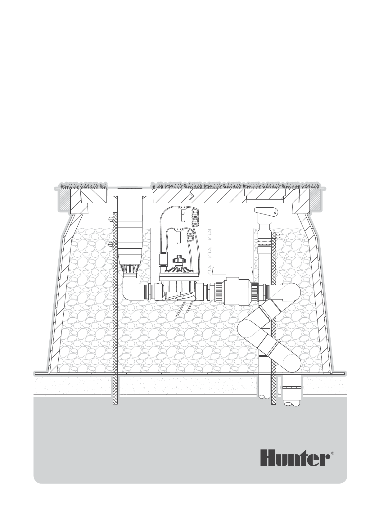
Installation Instructions for Hunter STG-900-KIT and STG-900-KIT-B
Synthetic Turf Rotor and Vault System
The Hunter STG-900-KIT synthetic turf rotor and vault
system is a special combination of products designed
specically to meet the unique needs of irrigation on synthetic
turf elds. Synthetic turf elds are a non-serviceable surface,
meaning they are not easily excavated and restored to original
condition without huge expense and specialized procedures.
As a result and to the extent possible, all serviceable
components of the irrigation system must be accessible from
the surface. The Hunter STG-900-KIT makes installation and
adjustment straightforward and exible. The STG-900-KIT
also provides easy access for the ongoing maintenance needs
of the end user.
Setting the ST-173026-B Vault
Set the vault according to the installation specications
provided by the irrigation consultant. It must rest upon a
compacted base material per the eld specications. If the
vault is to be set directly upon the gravel of the drainage
system, the gravel should be compacted and the vault set
upon six bricks for stabilization.
The elevation to grade of the vault must be precise and is
determined by the eld and irrigation specication. In many
installations, the elevation for the vault is specied such that
the upper rim of the vault is level with the tack/glue board
that surrounds the eld. The vault’s elevation can also be
aected by the type of material, if any, that will be attached
to the vault’s upper surface. Sometimes this will be the eld’s
synthetic “carpet” or the adjacent running track material.
Some customers prefer no attachments to the covers
because they want a player running toward the vault to see it
and take corrective action.
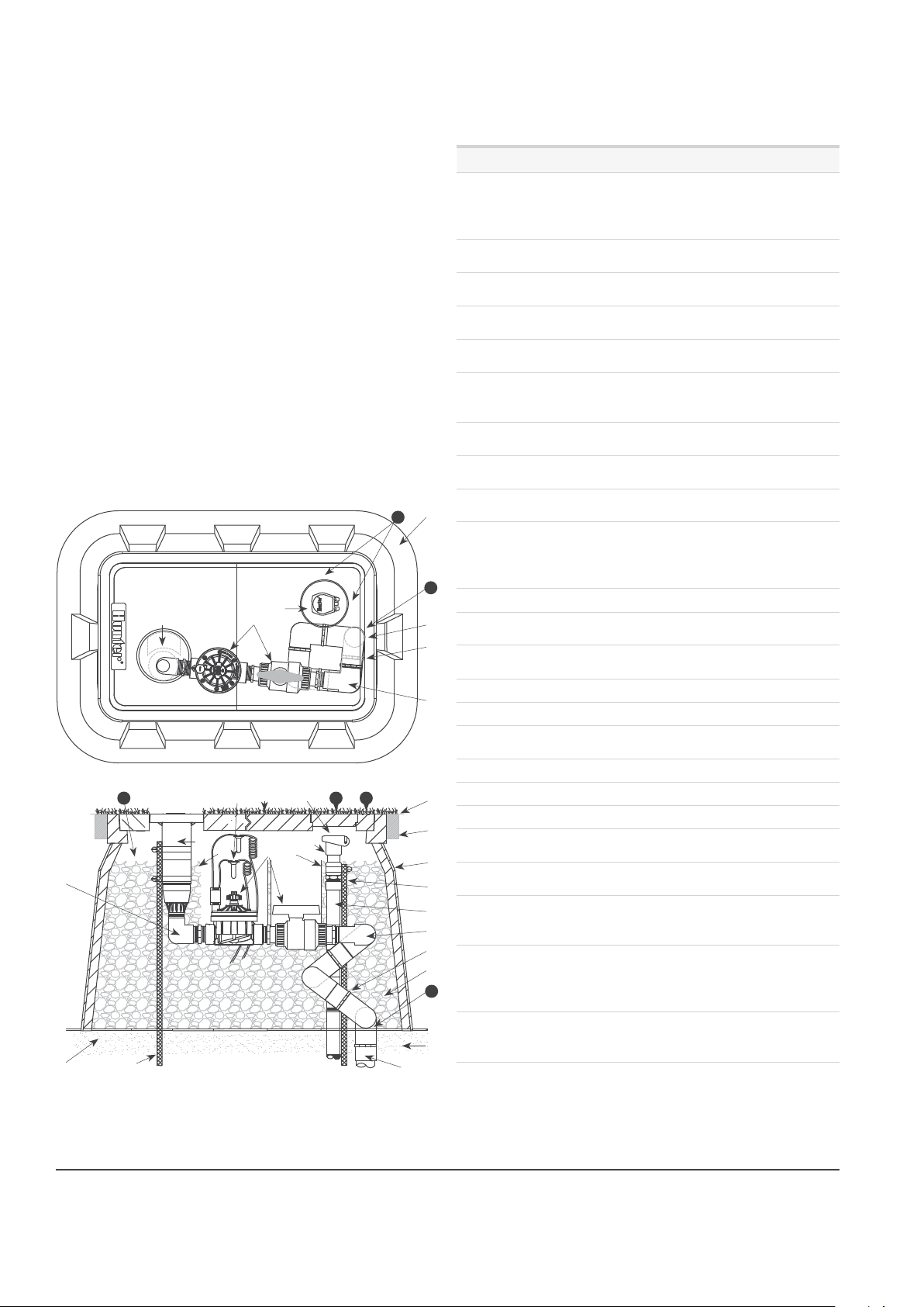
Incoming Plumbing Location
The swing joint’s inlet piping location and depth is critical.
This location and depth in conjunction with the special multiaxis vertical alignment (VA) swing joint allows the rotor to be
placed and leveled within the hole in the vault’s cover. Use
the top view of the following installation detail as a reference.
The bottom of the top view drawing represents the on-eld
side of the vault and the top of the drawing represents the
o-eld side. Next, note that the swing joint inlet is centered
along the right side wall of the vault’s upper rim (#23). The
swing joint’s inlet piping must not be any closer to the rotor
hole in the cover than this location. The swing joint’s inlet can
move outward to the point where it is centered under the
vault’s upper rim.
The quick coupler inlet piping must align with the quick
coupler access hole in the vault’s cover. Use the top view
illustration as a reference below. The rim of the vault is the
exposed upper surface that surrounds the vault’s covers once
they are installed. The quick coupler inlet piping needs to be
5" (12.7 cm) from the inner rim of the vault at the top and 5"
(12.7 cm) from the inner rim of the vault on the right side (#24).
With the STG-900-KIT, there is a direct and required
relationship between the location of the vault, the location
of the incoming plumbing, and the location and depth of the
drainage system. In order for the irrigation sprinkler (rotor)
to be properly positioned within the hole in the vault’s cover,
the swing joint’s inlet piping must be placed at the specied
location and depth. In order for the quick coupler valve to be
accessible and functional once installed, the quick coupler’s
supply pipe must be installed in the correct location and the
valve must be at the correct height within the vault. In order
for the vault to drain properly, it must have access to the
drainage system, and the drainage system must be lower in
elevation than the vault’s base (26" or 66 cm).
Vault Dimensions:
Two-piece cover - Upper Rim 20" x 33" (50.8 cm x 83.8 cm), Cover 17" x 30" (43.2 cm x 76.2 cm),
Depth 26" (66 cm), Base 27" x 41" (68.5 cm x 104.1 cm)
|
Visit hunterindustries.com/support
Page 3
Installation Instructions for Hunter STG-900-KIT and STG-900-KIT-B
Incoming Plumbing Elevation
The swing joint’s inlet piping location and depth is also
crucial. This location and depth in conjunction with the
VA swing joint allows the rotor to be placed and leveled
within the hole in the vault’s cover. Use the side view of the
following installation detail as a reference. Note that the VA
swing joint’s rst horizontal section is resting at a level that is
at the same level as the bottom of the vault (#22). This depth
is 26" (66 cm) from the top of the vault.
The quick coupler inlet piping (#13) must align with the quick
coupler access hole in the vault’s cover (#24). Also, in order
for the quick coupler key with its handle attached to operate
the quick coupler valve, the quick valve must be installed
as close to the underside of the main cover as possible. Use
the side view illustration shown below as a reference. The
quick coupler must be installed so that the nal elevation is
approximately ½" (1.2 cm) below the underside of the main
vault cover (#20).
O-Field Side
24
➊
⑪
➎
➏
⑫
⑭
⑩
On-Field Side
➒
⑱
21
➎
⑲
➋
⓴
⑪
➏ ➑➐
⑯
23
24
⑰
⑫
View from On-Field Side
Specication List for Installation Detail Drawings
ITEM DESCRIPTION
Hunter ST-173026-B composite vault and two-piece
polymer-concrete lid assembly with cast-in opening
1
to support rotor lateral thrust plus cast in opening
with circular cover for quick coupler access
Optional synthetic turf or running track material
2
attached to covers
Finished grade set to eld perimeter tack/glue
3
board or as per specication
2"x 4" (5.1 cm x 10.1 cm) tack/glue board as per
4
specication all sides
Hunter STG-900 rotor with rubber cover kit 473900
5
installed
Hunter ST-VBVF-K kit; includes Hunter ICV-151G, 1½"
6
ball valve (235 PSI rated) plus Acme pivot connection
ttings
Control valve sleeve, 8" (20.3 cm) diameter x 11"
7
(27.9 cm) tall with two notched sections for piping
Ball valve sleeve, 6" (15.2 cm) diameter x 11" (27.9
8
cm) tall with two notched sections for piping
Hunter 239800 rotor adapter tting with two Acme
9
pivot points
Prefabricated 2" (5.1 cm) PVC Hunter ST-2008-VA
swing joint with six Acme pivot points to provide
10
multi-axis articulation and alignment of rotor to the
23
➌
➍
➊
⑯
⑬
⑩
⑭
⑮
22
opening in vault cover
11 Hunter HQ-5RC quick coupling valve
Supply piping and tting – 2" (5.1 cm) minimum
12
from mainline through to ST-2008-VA swing joint
Schedule 80 PVC riser supply piping and tting; 1"
13
(2.5 cm) minimum
14 Acme threaded pivoting points (nine total)
15 ⁄" (1.9 cm) minus washed gravel
⁄" x 30" (1.6 cm x 76.2 cm) rebar stake and stainless
16
steel strapping
17 Compacted eld base material as per specication
18 Provide drainage via access to eld drainage system
19 Waterproof connections per specication
Top of quick coupler set ½" (1.3 cm) below underside
20
of vault cover
Gravel level 5" (12.7 cm) below the underside of the
21
vault cover (to bottom of rotor’s compartment)
Elevation of swing joint’s inlet: set second pivot
22
point on swing joint with bottom of vault per side
view detail drawing (26" (66 cm) below vault top)
Location of swing joint’s inlet: set inlet at edge
between vault covers and locate 5" (12.7 cm) from
23
the top of cover per top view detail drawing – inlet
must not be set closer to rotor than shown
Location of quick coupler inlet piping: measure inlet
24
piping location at top right corner of vault, 5" (12.7
cm) from top edge and 5" (12.7 cm) from side edge
Page 4
RESIDENTIAL & COMMERCIAL IRRIGATION | Built on Innovation
®
 Loading...