

Wireless
Wireless ET Sensor for Compatible Hunter Controllers
Owner’s Manual and Programming Instructions for:
• WSS: Wireless Solar Sync kit Pro-C, PCC, ICC, and I-Core controllers
• WSSSEN: Wireless Solar Sync kit for ACC and X-Core controllers
®

TABLE OF CONTENTS
INTRODUCTION................................................................................2
SYSTEM OVERVIEW AND OPERATION ...........................................2
SENSOR DETAILS ..............................................................................4
Installing the Sensor ......................................................................4
Clik Operation ...............................................................................5
Bypassing the Sensor ....................................................................5
Maintaining the Sensor..................................................................5
CONNECTING TO THE CONTROLLER .............................................6
Installing and Wiring the Module ..................................................6
Pro-C Conventional Controller (PCC Series) .................................7
Pro-C Controller (PC Series) .........................................................9
ICC Controller ............................................................................10
I-Core Controller .........................................................................11
X-Core Controller ........................................................................12
ACC Controller ............................................................................12
ADDRESSING WIRELESS RECEIVER/SENSOR ...............................13
PROGRAMMING CONTROLLER RUN TIMES .................................14
PROGRAMMING THE SOLAR SYNC MODULE ..............................15
CALIBRATION / SETUP PERIOD .....................................................18
TROUBLESHOOTING GUIDE ..........................................................19
SPECIFICATIONS / DIMENSIONS / FCC NOTICE...........................20
Controller Compatibility ..............................................................20
Specifications ..............................................................................20
Dimensions ..................................................................................20
FCC Notice ..................................................................................21
Industry of Canada Notice ..........................................................22
CE and Australia Notice ..............................................................22

INTRODUCTION
The Solar Sync is a sensor system that, when connected to a
compatible Hunter controller, will automatically adjust your
controller watering based upon changes in local climate conditions.
The Solar Sync utilizes a solar and temperature sensor to measure
on-site weather conditions used to determine evapotranspiration
(ET), or the rate at which plants and turf use water. In addition, Solar
Sync includes a Hunter Rain-Clik™ and Freeze-Clik™ sensor that
will shut down your irrigation system when it rains and/or during
freezing conditions.
A small module connects the sensor to the controller and will
automatically increase or decrease watering run times based on
changes in weather. The result is a new water-efficient irrigation
product that promotes water conservation and healthier plants.
You simply program your controller like you normally would, and
the Solar Sync takes over from there, eliminating the need to
manually adjust your watering schedule.
SYSTEM OVERVIEW AND OPERATION
The Wireless Solar Sync System is simply and easily installed on any compatible Hunter Irrigation controller (see Owner’s Manual to verify
compatibility). The Wireless Solar Sync Sensor measures solar radiation and temperature and calculates the daily evapotranspiration (ET)
factor for irrigation. This represents the amount of water lost by the plants due to local climate conditions, which needs to be replaced by
irrigation. The Wireless Solar Sync also includes Hunter Rain-Clik™ and Freeze-Clik® sensors that will automatically shut down the irrigation
system during rain events or freezing conditions.
Enter a mid summer watering program in your controller per the programming instructions in the Owner’s Manual provided with your
controller. The Wireless Solar Sync Sensor sends weather data and applies it daily to the controller’s water schedule by adjusting the
controller through the seasonal adjust feature.
This Owner’s Manual applies to the following kits:
• WSS: Wireless Solar Sync kit for Hunter Pro-C, PCC, ICC, and I-Core controllers
• WSSSEN*: Wireless Solar Sync kit for Hunter ACC and X-Core controllers
* Note that WSSSEN does not include the Solar Sync Module. The ACC and X-Core controllers have the Solar Sync software built in and do
not require the Solar Sync Module. Therefore, the WSSSEN should be used with the ACC and X-Core Controllers.
2
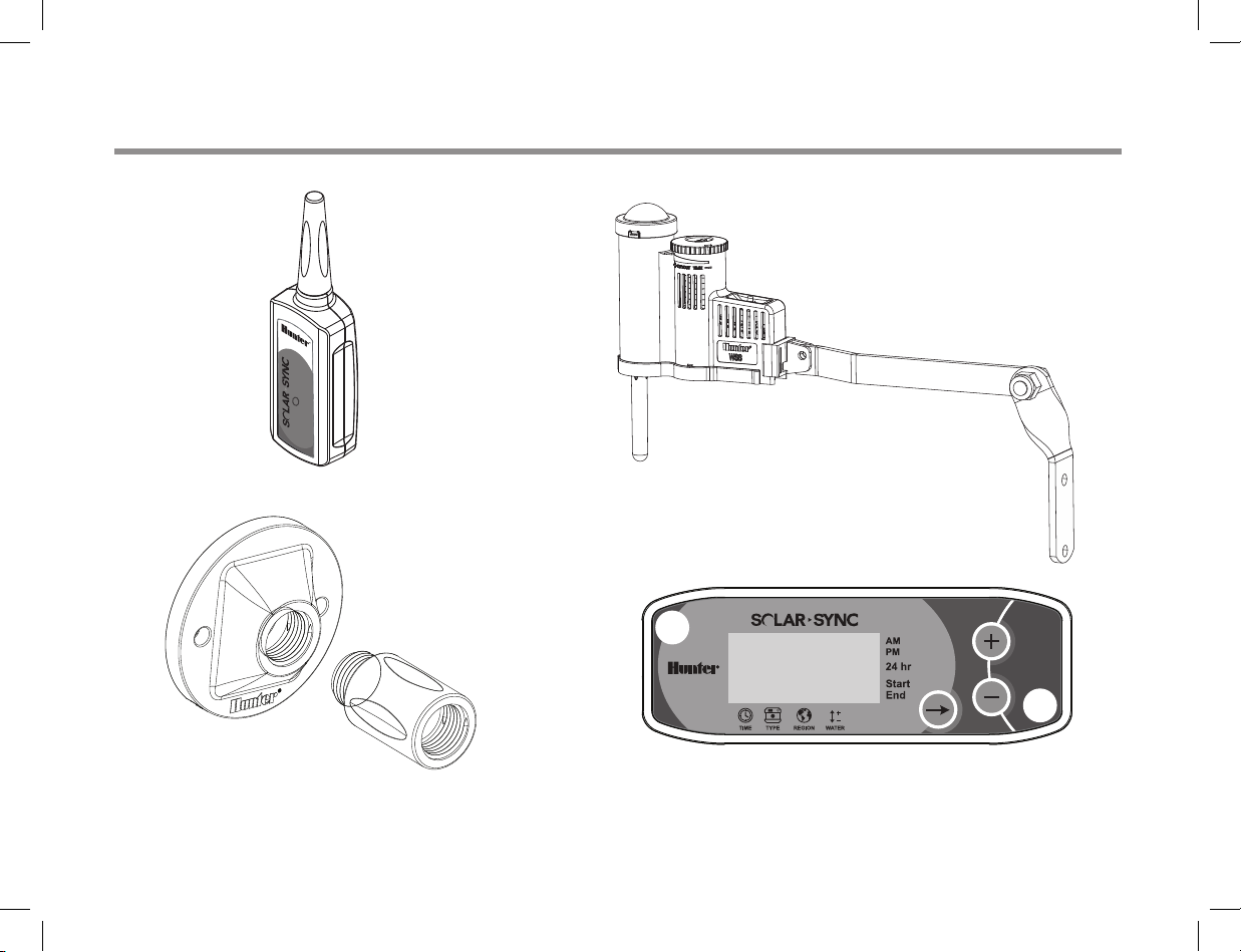
SYSTEM OVERVIEW AND OPERATION
®
Wireless Solar Sync Rec eive r
Wireless Solar Sync Sen sor
Sol ar S ync Modu leWall Mount Bracket
3
SENSOR DETAILS
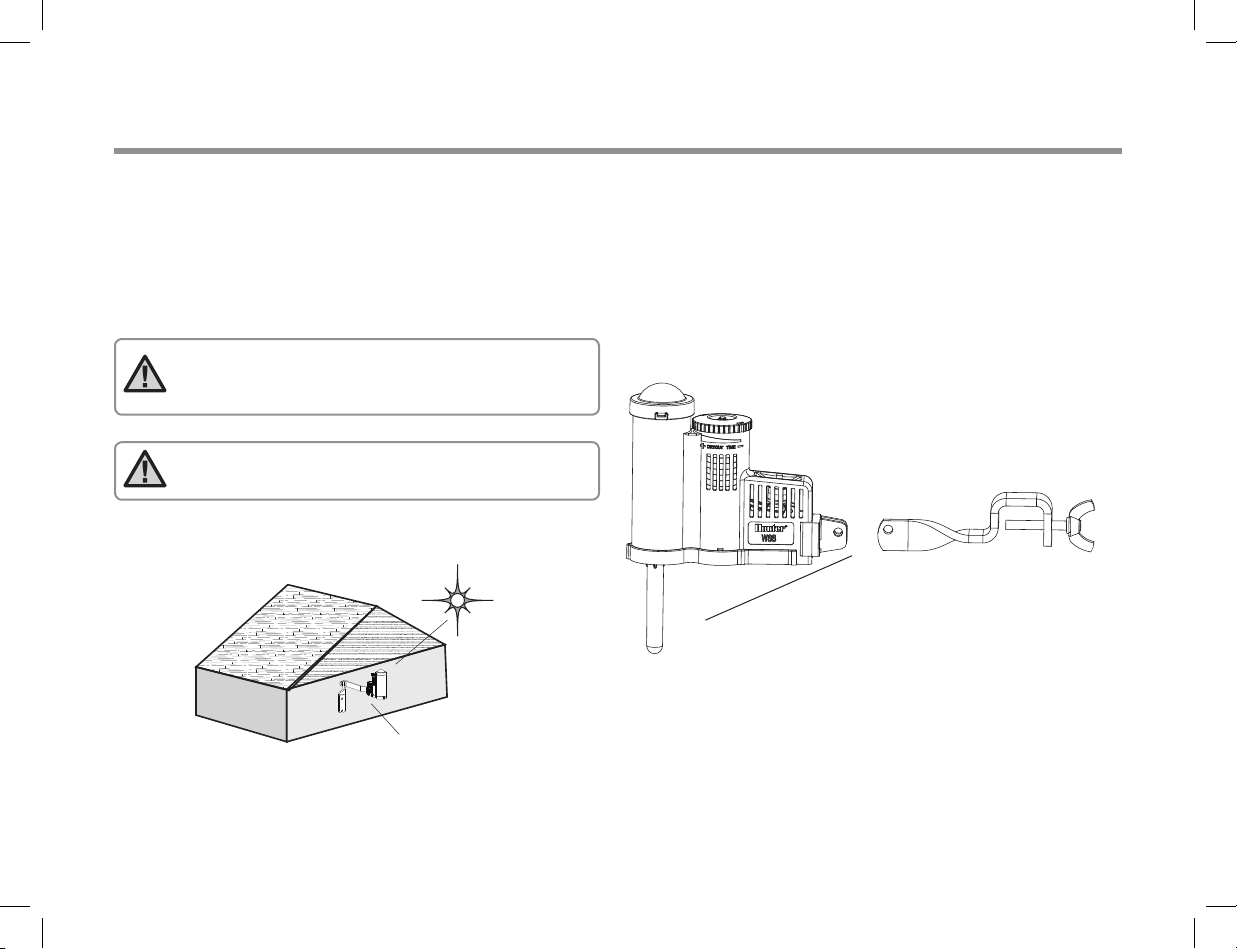
Installing the Sensor
Using the screws provided, mount the Solar Sync sensor on any
surface where it will be exposed to unobstructed sun and rainfall,
but not in the path of sprinkler spray. The sensor needs to be
oriented upright and the swivel bracket can be moved for mounting
on angled surfaces. Loosen the locknut and screw before swiveling
the bracket and then retighten.
Note:
The Wireless Solar Sync Sensor is designed
to operate to a maximum distance of 800 feet
(228 m) from the Wireless Receiver.
Note:
Place Solar Sync where it can receive full sun.
The Sensor Gutter Mount can also be used as an optional mounting
method. The Sensor Gutter Mount (SGM) allows the Sensor to be
mounted directly to the edge of a gutter. Install the SGM on the
Sensor by removing the extension arm supplied with your Sensor
and reinstalling SGM in its place. Position the SGM on the edge of
the gutter and secure by twisting the thumb screw.
Sun
Solar Sync
Re- use screw and nut from original extension arm
4
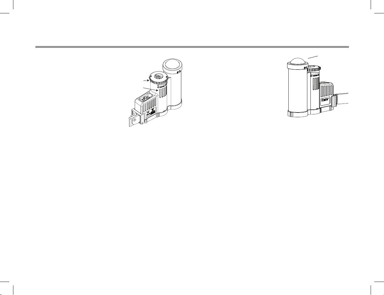
SENSOR DETAILS
Clik Operation
The Rain-Clik™ will keep the irrigation
from starting or continuing during
rainfall. No adjustment or calibration
is required for the Rain-Clik™ sensor.
The Rain-Clik™ uses patented Quick
Response™ technology that will shut
the system off during the first few
minutes of rain. The only adjustment
that is necessary is the vent ring that
will either slow down or speed up the
time at which the sensor dries out and
the system is turned back on. Opening the vent will speed up the
dry out time and closing the vents will slow down dry out time.
In addition, the Solar Sync’s built-in temperature sensor provides
system shutdown when freezing conditions occur. At approximately
37˚ F/3˚ C and below the Solar Sync module will command the
controller to shut down. A “sensor off” indication will be displayed
on your controller when the sensor is active. When temperatures
rise above 37˚ F/3˚ C, automatic irrigation will be activated at the
next scheduled start time.
Vent Ring
Vents
Bypassing the Sensor
Dom e
If the Rain Sensor or Freeze Sensor
is preventing system operation,
SENSOR OFF
the controller’s display. Simply move
the Bypass switch on the controller to
BYPASS
Freeze Sensor will be bypassed. This
allows you to operate your system.
The Solar Sync will continue to make
adjustments to your controller’s
watering schedule.
The controller’s Rain Sensor switch should be in the ACTIVE
position for the Rain Sensor and Freeze Sensor to interrupt watering
during rainy and/or freezing conditions.
will be displayed on
and the Solar Sync’s Rain and
Maintaining the Sensor
The Solar Sync sensor is designed for outdoor use, but must be
kept clean to function correctly. Wiping the clear dome covering the
solar radiation sensor every 6 months is recommended. Do not use
harsh chemicals or abrasives on the clear dome.
5
CONNECTING TO THE CONTROLLER
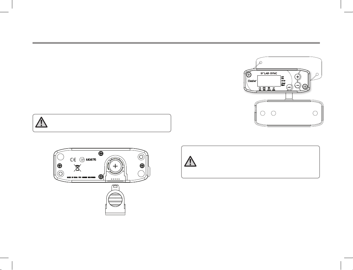
Installing and Wiring the Module
Begin by activating the CR2032 backup battery (used for date/
time backup in the event of a power outage) by pulling the battery
insulator at the bottom of the module. The expected battery
life is ten years. If the battery requires replacement, the battery
compartment is located on the back of the Solar Sync module.
Remove the cover and install the battery with the positive side (+)
of the battery visible, facing toward you. Replace the battery cover.
Replace battery with CR2032 type battery only. Use of another
battery may present a risk of fire or explosion.
Note:
Battery may explode if mistreated. Do not
recharge, disassemble or dispose of in fire.
The Solar Sync module
is designed to be
wall-mounted next to the
irrigation controller. A
rubber cover is provided
for outdoor installations
to protect the module
from the weather. Use two
anchors or self-tapping
screws to secure the
module to the wall.
Place the rubber cover
mounting tab behind the
module before screwing
the module to the wall.
Note:
If you are installing Solar Sync on an ACC or
X-Core Controller, the Solar Sync Module is not required.
For the ACC or X-Core controllers, the WSSSEN kit should
be used, as it does not include the Module. (See the
controller‘s owner‘s manual for more details.)
6
CONNECTING TO THE CONTROLLER
®
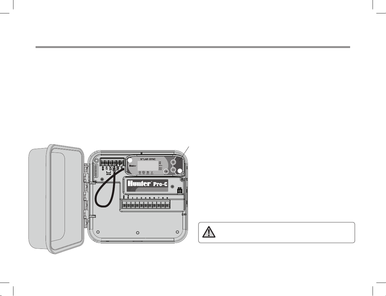
Pro-C Conventional Controller (PCC Series)
The PCC series version of the Pro-C is designed so that the Solar Sync module can be installed inside the controller cabinet.
Use the two screws provided to mount the module as shown in the diagram.
1. Connect the
2. Connect the
3. Connect the
4.
Remove
5. Connect the
6. Connect the
red
wire from the Solar Sync module to the AC1 terminal
white
wire from the Solar Sync module to the AC2 terminal
blue
wire from the Solar Sync module to the REM terminal
the flat metal jumper from the two SEN terminals
yellow
wire to one of the SEN terminals
orange
wire to the other SEN terminal
Pro-C PCC Controller
P C C S E R I E S
Sol ar S ync Modu le
Note:
For Pro-C PCC Series controllers, there are provisions
inside the controller to mount the Solar Sync module.
Controller Connections
SEN: ORANGE
SEN: YELLOW
REM: BLUE
AC2: WHITE
AC1: RED
7

CONNECTING TO THE CONTROLLER
®
P C C S E R I E S
SEN: ORANGE
SEN: YELLOW
REM: BLUE
Controller Connections
AC2: WHITE
AC1: RED
Pro-C Conventional Controller (PCC Series)
Mount the Wireless Receiver on the controller cabinet using an available knock out and secure with the supplied conduit nut. Or, use the
supplied brackets to mount the Wireless Receiver on the wall. Depending on the installation, the supplied 1.5" (3.8 cm) extender may be
required (shown below). Route the wires from the Wireless Receiver into the controller cabinet.
1. Make sure power to the controller is turned off
2. Connect the
3. Connect the
4. Initialize communication by following steps outlined in “Addressing Wireless Receiver/Sensor” section on page 13
black
Receiver wire to the black Module wire
green
Receiver wire to the green Module wire
1.5 " ex tend er
(op tion al u se)
Green
Bla ck
Wall Mount Option
Wireless Receiver
Mou nted to Cont roller
8

CONNECTING TO THE CONTROLLER
®
Pro-C Controller (PC Series)
For the PC series Pro-C Modular controller, mount the Solar Sync module on the
wall next to the controller cabinet. There is an additional knockout on the right side
of the controller cabinet to route Solar Sync wires into and out of the cabinet.
1. Connect the
2. Connect the
3. Connect the
4.
Remove
5. Connect the
6. Connect the
Mount the Wireless Receiver on the controller cabinet using the options described on page 8. Due to the position of the power module in
the Pro-C controller, a more convenient option may be to mount the Wireless Receiver to the wall using the Wall Mount Bracket.
1. Make sure power to the controller is turned off
black
2. Connect the
3. Connect the
Receiver wire to the black Module wire
green
Receiver wire to the green Module wire
4. Initialize communication by following steps outlined in “Addressing Wireless Receiver/Sensor” section on page 13
red
wire from the Solar Sync module to the AC1 terminal
white
wire from the Solar Sync module to the AC2 terminal
blue
wire from the Solar Sync module to the REM terminal
the flat metal jumper from the two SEN terminals
yellow
wire to one of the SEN terminals
orange
wire to the other SEN terminal
9

CONNECTING TO THE CONTROLLER
®
ICC Controller
1. Connect the
2. Connect the
Yellow
Orange
3. Connect the
4.
Remove
5. Connect the
Blue
White
Red
6. Connect the
Mount the Wireless Receiver on the controller cabinet using an available knock out and secure with the supplied conduit nut, similar to the
Pro-C installation shown on page 8. Or, use the supplied brackets to mount the Wireless Receiver on the wall. Depending on the installation,
the supplied 1.5" (3.8 cm) extender may be required. Route the wires from the Wireless Receiver in to the controller cabinet.
1. Make sure power to the controller is turned off
2. Connect the
3. Connect the
black
Receiver wire to the black Module wire
green
Receiver wire to the green Module wire
4. Initialize communication by following steps outlined in “Addressing Wireless Receiver/Sensor” section on page 13
red
wire from the Solar Sync module to the AC1 terminal
white
wire from the Solar Sync module to the AC2 terminal
blue
wire from the Solar Sync module to the REM terminal
the flat metal jumper from the two SEN terminals
yellow
wire to one of the SEN terminals
orange
wire to the other SEN terminal
10

CONNECTING TO THE CONTROLLER
S1 S1 S2 S2 C C
GND AC1 AC2 REM C
P/MV
I-Core Controller
1. Connect the
2. Connect the
3. Connect the
4.
Remove
5. Connect the
6. Connect the
Yellow
Blue
White
Red
Orange
Mount the Wireless Receiver on the controller cabinet using an available knock out and secure with the supplied conduit nut. Or, use the
supplied brackets to mount the Wireless Receiver on the wall. Depending on the installation, the supplied 1.5" (3.8 cm) extender may be
required. Route the wires from the Wireless Receiver in to the controller cabinet.
1. Make sure power to the controller is turned off
black
2. Connect the
3. Connect the
Receiver wire to the black Module wire
green
Receiver wire to the green Module wire
4. Initialize communication by following steps outlined in “Addressing Wireless Receiver/Sensor” section on page 13
red
wire from the Solar Sync module to the AC1 terminal
white
wire from the Solar Sync module to the AC2 terminal
blue
wire from the Solar Sync module to the REM terminal
the flat metal jumper from the two SEN terminals
yellow
wire to one of the SEN terminals
orange
wire to the other SEN terminal
Sol ar S ync Modu le
11

CONNECTING TO THE CONTROLLER
X-Core Controller
The X-Core Controller is programmed with Solar Sync technology and, therefore,
does not require the use of the Solar Sync module. Simply mount the Wireless
Receiver on the controller cabinet using an available knock out and secure with the
supplied conduit nut. Or, use the supplied brackets to mount the Wireless Receiver
on the wall, similar to the Pro-C installation shown on page 8. Depending on the
installation, the supplied 1.5" (3.8 cm) extender may be required. Route the wires
from the Wireless Receiver in to the controller cabinet.
1. Make sure power to the controller is turned off
2. Connect the
matter which “SEN” terminal is used)
3. Connect the
See X-Core owner’s manual for further details.*
black
Receiver wire to the “SEN” Terminal location (it does not
green
Receiver wire to the other “SEN” terminal location
ACC Controller
The ACC Controller is programmed with Solar Sync technology and, therefore, does not
require the use of the Solar Sync module. Simply mount the Wireless Receiver on the
controller cabinet using an available knock out and secure with the supplied conduit nut.
Or, use the supplied brackets to mount the Wireless Receiver on the wall, similar to the
Pro-C installation shown on page 8. Depending on the installation, the supplied 1.5"
(3.8 cm) extender may be required. Route the wires from the Wireless Receiver in to the
controller cabinet.
1. Make sure power to the controller is turned off
2. Connect the
3. Connect the
See ACC owner’s manual for further details.*
black
Receiver wire to the black “ET” terminal on the master module
green
Receiver wire to the green “ET” terminal on the master module
12
Note:
*The X-Core and ACC controllers have the Solar Sync software built in.
Please see the controllers’ owner’s manuals for Solar Sync programming instructions.
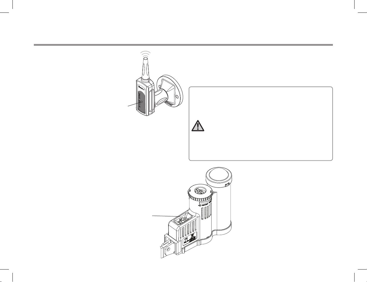
ADDRESSING WIRELESS RECEIVER/SENSOR
The Wireless Solar Sync Receiver
and Sensor are already paired with
the same frequency for an easy
installation. When installed, the
wireless Receiver will automatically
go into a “search” mode looking
for the signal from its paired Sensor.
However, it is a good idea to initialize
communication manually between
the wireless Receiver and Sensor
during installation to verify correct
signal transmission.
To initialize communication manually between wireless Receiver
and Sensor:
• After Receiver’s green and black wires have been connected
(see “Connecting To The Controller” section), restore power
to the controller
• The red LED in the center of the wireless Receiver will turn
on and stay solid for 10 seconds, indicating that it is in search
mode, searching for a signal from a wireless sensor
• While the red LED is solid and the wireless Receiver is in search
mode, press and hold the spindle on the wireless Sensor. The
LED on the wireless Receiver will blink 4 times and then turn
off, indicating that the signal from the wireless Sensor has
been acknowledged.
LED
spindle
To Validate Receiver/Sensor Communication or Re-address:
• Press and hold the spindle on the wireless Sensor
• The LED on the wireless Receiver will blink 2 times, confirming
that the Receiver is addressed to the Sensor properly
Note: In the event of a power outage (or any other
reason when the Receiver loses radio contact with
the wireless Sensor) the Receiver will automatically
go into search mode to re-establish communication
with the Sensor once power is restored. However,
when power is restored the controller will automatically go into rain shut off mode until communication
with the Sensor is re-established, which may be up
to 60 minutes (maximum). Performing the steps listed
above to validate Receiver/Sensor communication will
remove the controller from rain shut off mode and
will return to its programmed irrigation schedule.
13

PROGRAMMING CONTROLLER RUN TIMES
Program your Hunter controller as specified in the Owner’s Manual.
When setting station run times, enter the time that would normally
be programmed during the peak summer watering season.
Solar Sync is designed to adjust all run times daily based upon
on-site weather conditions. This is done through the seasonal
adjustment feature on your controller. It is recommended that
all programming be conducted with the controller Seasonal
Adjustment set at 100%.
Note:
Set station run times for peak summer watering
with seasonal adjustment set at 100%.
The
14

PROGRAMMING THE SOLAR SYNC MODULE
The Solar Sync is simple to program. Only a few initial steps are necessary to program the module. When power is initially turned on, the
display will show the time of day. Pressing the button will sequence through the programming functions on the module. An arrow along
the bottom of the display will indicate the function being programmed.
If using the Solar Sync with the ACC or X-Core Controllers, consult the controller owner’s manual for programming details. (ACC and X-Core
controllers do not use the Solar Sync module.)
Current Time
Press the button press until the arrow is displayed over the
Use the or button to set the current time. The arrow to the right of the display indicates AM or PM.
Note:
24 hour mode will only be enabled with a 50 Hz power input.
icon. The time of day will be flashing.
Controller Type
Press the button until the arrow is displayed over the
Hunter controller.
icon. Use the or button to select the correct
Region
For accurate measurements, the Solar Sync module needs to be programmed for the typical ET
(average July ET) for your region. Use the table on the next page to determine your region. Press the
button until the arrow is displayed over the
(regions 1 through 4).
icon. Use the or button to select your region
15

PROGRAMMING THE SOLAR SYNC MODULE
The table will assist you in identifying the type of region you live
in. There are four basic ET regions, each with descriptions of the
region, along with typical ET and temperature characteristics. It is
recommended that, if possible, the region be chosen based upon
average July ET or peak summer ET (inches/mm per day).
Use the following table for choosing your region (reference below).
You can use A, B or C to help you choose which region is best for
your area:
IF ANY OF THE CHOICES IN THE ROWS APPLY TO YOUR SITUATION, THEN THAT IS YOUR REGION SETTING CHOICE.
A B C
Region
Region
Region
Region
1
2
3
4
If the average July ET is
< 0.17" (4.3 mm) per day
If the average July ET is 0.18" – 0.23"
(4.6 mm – 5.8 mm) per day
If the average July ET is 0.24" – 0.29"
(6.1 mm – 7.4 mm) per day
If the average July ET is > 0.30"
(7.6 mm) per day
If the average temperature for July is
65°– 75°
If the average temperature for July is
75° – 85°
If the average temperature for July is
85° – 95°
If the average temperature for July is
95° – 105°
A:
Based upon the ET of your region using the
peak summer ET (inches/mm per day). This is the preferred option
when selecting your region
B:
Based upon the temperature for your region using the
July or the driest month high temperature (not the highest
temperature for July)
C:
Based upon the general description of your region
(18°C – 24°C)
(24°C – 29°C)
(29°C – 35°C)
(35°C – 41°C)
• U.S. Northern States
• Coastal Regions
• Mountains
• U.S. Northern Inland States
• U.S. Southern States
• Inland/High Desert
• Deserts
average
July ET or
average
* For Southern hemisphere locations, use the month of January.
16

PROGRAMMING THE SOLAR SYNC MODULE
Watering Adjustment
If you find that your landscape is “wetter” or “drier” than it should be, a watering adjustment function is provided to
adjust watering equally to all stations. Use the button on the module until the arrow is displayed over the
Use the or button to increase or decrease the amount of watering scaled 1 to 10 (1 for less water and 10 for
more water). Hunter recommends observing performance carefully over the first weeks of operation before adjusting
the watering.
Note: If an individual zone is “wetter” or “drier” than the rest of the system, simply increase
or decrease the amount of run time on the controller.
icon.
No Water Window
If required, the Solar Sync offers
specific period of the day. The No Water Window is a hidden feature. Press and hold the button on the module
for 5 seconds to program the No Water Window.
An will be flashing at Start along the right side of the display. Use the or button to adjust the time you would
like the no watering period to start. Pressing the button again will display an arrow flashing at End. Use the or
button to adjust the time you would like the no watering period to end.
a no water window
capability that prevents any irrigation from occurring during a
17

CALIBRATION / SETUP PERIOD
After Solar Sync has been installed and programmed, it is recommended to allow the system to run for a few days at the initial setting.
Because of the variety in site conditions (including sensor location, amount of direct sunlight available to the sensor, reflective heat from
surrounding structures, etc),
Solar Sync to a particular site can easily be accomplished by adjusting the Region and/or Water Adjustment settings. The instructions below
outline this process:
1. Install Solar Sync sensor and program the module (as described in pages 10–12)
2. Allow system to operate at initial settings for a minimum of 3 days
3. Observe the Seasonal Adjust on the controller. If the Seasonal Adjust amount appears to be lower or higher than expected for that time
of year, the Solar Sync settings need to be adjusted.
a. Seasonal Adjust too low: Make sure controller dial is in the “Run” position. Increase the value on the Water Adjustment scale (10 is max).
b. Seasonal Adjust too high: Make sure controller dial is in the “Run” position. Decrease the value on the Water Adjustment scale (default
Station Run Times:
all station run times will be modified by the seasonal adjust percentage shown. When programming the controller, the run times should be
entered that represent peak season watering schedules. If the Solar Sync is adjusting to the appropriate seasonal adjust value but the run
time for a particular station appears to be too long/short, adjust the station run time in the controller program.
times, make sure the seasonal adjust valve is set to 100%.
Once the setting is changed, the controller will immediately be updated with the new Seasonal Adjust %. Increase the Water
Adjustment setting until the desired Seasonal Adjust % is shown. If you max out the Water Adjustment scale at 10 and still require
more Seasonal Adjust, move down to the next lower Region (from Region 4 to 3, for example).
setting is 5). Once the setting is changed, the controller will immediately be updated with the new Seasonal Adjust %. Decrease the
Water Adjustment setting until the desired Seasonal Adjust % is shown. If you minimize the Water Adjustment scale down to 1 and still
require a reduction in Seasonal Adjust, move up the next Region (from Region 2 to 3, for example).
It is important to understand that Solar Sync provides a global seasonal adjustment to the controller. This means that
the initial setting may require adjustment in order to arrive at the desired performance.
When adjusting station run
The calibration of the
18

TROUBLESHOOTING GUIDE
Problem Causes Solutions
Controller shows “ERR” in display
Solar Sync module shows “ERR”
Seasonal Adjust seems low
Seasonal Adjust seems high
Rain or Freeze shutoff not activating
Run times for a particular station are
too short/too long
Solar Sync still sending Seasonal
Adjust when Controller Bypass
switch in the “Bypass” position
Hunter Technical Service:
1-800-733-2823 or www.hunterindustries.com/Support/Ask_Expert/default.htm
•
Module wires not properly
connected to controller terminal
•
Connection between module and
sensor faulty
•
Region too high
•
Water Adjustment Setting too low
•
Location of Sensor does not allow
for full sun
•
Region too low
•
Water Adjustment setting too high
•
Rain Sensor Bypass Switch on
Controller set to “Bypass”
•
Jumper Clip still on controller
wiring terminal
•
Program Run Time too long/
too short
•
Solar Sync’s automated seasonal
adjustment cannot be de-activated
by the Bypass switch
•
The Bypass switch only controls the
Rain/Freeze shutoff function of the
Solar Sync
Check the connection between module and controller and compare to
wiring diagram in System Installation section of Owner’s Manual
Check connection between module and sensor (green and black wires)
Make sure controller dial is in “RUN” position. Increase the value on
the Water Adjustment scale (the default setting is 5). If you max out
the Water Adjustment scale at 10 and still require more seasonal
adjustment, move down one Region (from 4 to 3, for example) and start
at Water Adjustment setting 5. Solar Sync will immediately update the
Seasonal Adjust on the controller. If it is still too low, repeat the adjustment until the desired seasonal adjust is showing on the controller.
Make sure controller dial is in “RUN” position. Decrease value of the
Water Adjustment setting. If you minimize the Water Adjustment scale
at 1 and still require a reduced seasonal adjustment, move down up
one Region (from 2 to 3, for example) and start at Water Adjustment
setting 5. Solar Sync will immediately update the Seasonal Adjust
on the controller. If it is still too high, repeat the adjustment until the
desired seasonal adjust is showing on the controller.
Set the Controller Bypass Switch in the “Active” position.
Remove jumper clip.
Solar Sync provides a global seasonal adjustment to the controller.
If a particular station has run times too long or too short, make the
appropriate adjustment to the program in the controller.
19

SPECIFICATIONS / DIMENSIONS / FCC NOTICE
Controller Compatibility
The Solar Sync is designed for use with Hunter controllers that are
enabled with a Smart Port connection.
WSS: Wireless Solar Sync kit, for use with Hunter Pro-C, PCC, ICC,
and I-Core Controllers
WSSSEN: Wireless Solar Sync kit (no module included), for use with
Hunter ACC and X-Core controllers
Specifications
• Power Input: 24 VAC 50/60 HZ (from controller)
• Current draw: 25 mA at 24 VAC
• Non Volatile Memory
• Replaceable 10 year lithium battery: CR2032 (in module)
• 10 year battery (wireless)
• Maximum distance module from controller: 6 ft (2 m)
• Maximum distance Receiver to Module: 6 ft (2 m)
• Maximum distance Sensor to Receiver: 800 ft (228 m)
• Wiring: 18 AWG/1 mm or 20 AWG/0.8 mm diameter
minimum from Sensor to Module
• UL Listed
• Direct Burial and UV approved
Dimensions
Sensor:
3" H x 9" W x 1" D
(7.6 cm x 22.9 cm x 2.5 cm)
Module:
13⁄4" H x 5" W x 5⁄8" D
(4.4 cm x 12.7 cm x 0.6 cm)
Receiver:
5.5"H x 1.5" W x 11⁄2" D
(14 cm x 3.8 cm x 3.8 cm)
Receiver with Wall Mount Bracket:
61⁄8" H x 2¾" W x 31⁄2" D
(15.5 cm x 7 cm x 8.9 cm)
20

SPECIFICATIONS / DIMENSIONS / FCC NOTICE
FCC Notice
Transmitter FCC ID : M 3USSW
This device complies with FCC rules Part 15. Operation is subject to the following two conditions:
1. This device may not cause harmful interference and
2. This device must accept any interference that may be received, including interference that may cause undesired operation
This equipment has been tested and found to comply with the limits for class B digital device, pursuant to part 15 of the FCC Rules. These
limits are designed to provide reasonable protection against harmful interference in a residential installation. This equipment generates, uses,
and can radiate radio frequency energy and, if not installed and used in accordance with the instructions, may cause harmful interference
to radio communications. However, there is no guarantee that interference will not occur in a particular installation. If this equipment does
cause harmful interference to radio or television reception, which can be determined by turning the radio equipment off and on, the user is
encouraged to try to correct the interference by one or more of the following measures:
• Reorient or relocate the receiving antenna
• Increase the separation between the equipment and receiver
• Connect the equipment into an outlet on a circuit different from that to which the receiver is connected
• Consult the dealer or an experienced radio/TV technician for help
The user is cautioned that changes and modifications made to the equipment without the approval of the manufacturer could void the user’s
authority to operate this equipment.
Trade Name
Model Number
Compliance Test Report
Number
Compliance Test Report Date
Responsible Party
Address
Telephone
Wireless Solar Sync
WSSR
B00217D4
1/29/2010
Hunter Industries Incorporated
1940 Diamond St, San Marcos,
CA 92078
760-744-5240
I, the undersigned, hereby declare that the equipment specified
above conforms to the above requirements.
Signature:
Place: San Marcos, CA Full Name: Peter Woytowitz
Date: March 22, 2010 Position: Engineering Manager
21

SPECIFICATIONS / DIMENSIONS / FCC NOTICE
Industry of Canada Notice
Sensor - IC: 2772A-SSW
Receiver - IC: 2772A-SSWR
Operation is subject to the following conditions:
• This device may not cause harmful interference and
• This device must accept any interference received, including interference that may cause undesired operation
This class B digital apparatus complies with Canadian ICES-003.
The term IC before the certification/registration number only signifies that the Industry of Canada technical specifications were met.
Operation is subject to the following conditions: 1) this device may not cause interference, and 2) this device must accept any interference,
including interference that may cause undesired operation in the device.
CE and Australia Notice
Hunter Industries hereby declares that this remote control device is in compliance with the essential requirements and other relevant
provisions of Directive 1999/5/CE.
Declaration of Conformity: We, Hunter Industries Incorporated, 1940 Diamond Street, San Marcos, CA 92078, declare under our own
responsibility that the Wireless Solar Sync, model numbers WSSTR and WSSR, to which this declaration refers, conforms with the relevant
standards:
Emissions: ETSI EN 300 220-1 V2.1.1 Immunity: ETSI EN 301 489-1 V1.4.1
ETSI EN 300 220-2 V2.1.1 (per IEC61000-4-2 through IEC61000-4-6, and IEC61000-4-11)
ETSI EN 301 489-1 (per EN55022)
EN 61000-3-2
EN 61000-3-3
Signature:
Place: San Marcos, CA Full Name: Peter Woytowitz
Date: March 22, 2010 Position: Engineering Manager
22

NOTES
23

NOTES
24

NOTES
25

Hunter Industries Incorporated • The Irrigation Innovators
© 2010 Hunter Industries Incorporated
1940 Diamond Street • San Marcos, California 92078 USA LIT-520 3/10
www.hunterindustries.com
 Loading...