

Page 1
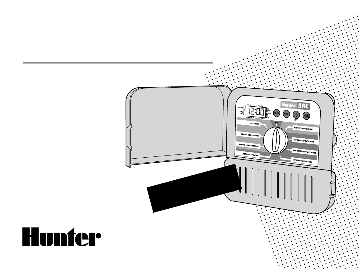
SRC
Residential/Light Commercial
Irrigation Controller
Owner’s Manual and
Programming Instructions
600i 6-station Indoor Model
601i
900i
901i
MPC Optional Outdoor Cabinet
6-station Indoor Model
(International)
9-station Indoor Model
9-station Indoor Model
(International)
®
NOW WITH
NON-VOLATILE MEMORY
Page 2

2
3
Page 3

TABLE OF CONTENTS .............................................................................................................
INTRODUCTION AND INSTALLATION
Introduction ............................................................................................................................................................................................. .....1
SRC Components............................................................... ............................................................... ..........................................................2-3
Mounting Controller to Wall ........................................................................................................................................................................... 4
Mounting the Controller Outdoors (MPC)........................................................................................................................................................ 5
Connecting Valves and Transformer................................................................................................................................................................ 6
Connecting the Battery................................................................................................................................................................................... 7
Connecting a Master Valve .............................................................................................................................. ............................................... 7
Connecting a Pump Start Relay ............................................................... ............................................................... ....................................... 8
Connecting a Weather Sensor ............................................................... ............................................................... .......................................... 9
Connecting a SRR or ICR Remote Control..................................................................................................................................................... 11
Connecting to IMMS® Central Control System ............................................................................................................................................... 11
Power Failures............................................................................................................................................................................................. 11
CONTROLLER PROGRAMMING AND OPERATION
Sprinkler System Fundamentals ................................................................................................................................................................... 12
Programming Fundamentals............................................................... ............................................................... ........................................... 13
Creating a Watering Schedule....................................................................................................................................................................... 14
How to Fill Out the Watering Schedule Form ............................................................... ............................................................... ................... 14
Watering Schedule Form .............................................................................................................................................................................. 15
Programming the Controller
Setting the Date and Time ........................................................................................................................................................................ 16
Setting Watering Start Times .............................................................................................................................. ...................................... 17
Eliminating a Program Start Time ............................................................................................................................................................. 17
3
Page 4

1
TABLE OF CONTENTS (Continued) .......................................................................................
Programming the Controller
Setting Station Run Times (Length of Watering for Each Area) .................................................................................................................. 18
Setting Days To Water .............................................................................................................................................................................. 18
Selecting Specific Days of the Week to Water............................................................................................................................................ 18
Selecting Odd or Even Days ..................................................................................................................................................................... 19
Run ......................................................................................................................................................................................................... 19
Weather Sensor Bypass ........................................................................................................................................................................... 19
System Off ............................................................... ............................................................... ................................................................ 19
Manually Run a Single Station ............................................................... ............................................................... .................................... 19
Manually Run All Stations ........................................................................................................................................................................ 20
One Touch Manual Start and Advance .............................................................................................................................. ......................... 20
TROUBLESHOOTING AND SPECIFICATIONS
Troubleshooting Guide ............................................................................................................................................................................ 21-22
Frequently Asked Questions ............................................................... ............................................................... ...................................... 23-24
Specifications.............................................................................................................................................................................................. 25
FCC Notice ..................................................................................................................................................................................... Back Cover
Page 5

INTRODUCTION .......................................................................................................................
Finally, there’s an affordable controller for your home.
Hunter Industries is pleased to present the SRC – a Simple and Reliable Controller for residential applications. Designed with the needs of the
customer in mind, the SRC offers simplified dial programming and an impressive range of features typically found in controllers costing twice
as much.
While it’s affordable, the SRC is without a doubt a professional grade product. The controller’s large, handsome cabinet, complete with a protective
door, provides your controller with a neat and professional appearance. And, the SRC is filled with the essential features that landscapes demand (like
a rain sensor bypass circuit and primar y power surge protection), but without some of the unnecessary frills that often lead to contractor call back.
The SRC is so easy to use that after reading this User Guide thoroughly, you will need it very little after installation. We have also included an
abbreviated instruction sheet inside the door of the controller for quick reference later on.
After a few uses of this controller, you can be sure the SRC is a product that does the job efficiently and economically.
1
Page 6

3
SRC COMPONENTS .................................................................................................................
RUN
NEXT
PROGRAM
START
TIMES
STATION RUN TIME
YEAR
MONTH
DA
Y
RUNNING
AM
PM
24 HR.
SUN MON TUES WED
THUR
FRI SAT EVEN/ODD
SYSTEM OFF
RUN (BYPASS SENSOR)
SET DAYS TO WA
TER
MANUAL - SINGLE ST
ATION
MANUAL - ALL ST
ATIONS
SET CURRENT DATE/ TIME
SET WATERING START TIMES
SET STATION RUN TIMES
AC AC R RS C MV 1 2 3 4 5 6FUSE 0.75A
9 V Battery
A
B
C
1
2
3
4
PROGRAM
START
TIMES
STATION RUN TIME
YEAR
MONTH
DA
Y
RUNNING
AM
PM
24 HR.
SUN MON TUES WED
THUR
FRI SAT EVEN/ODD
PROGRAM
START
TIMES
STAT
A
B
C
1
2
3
4
PROGRAM
START
TIMES
STATION RUN TIME
YEAR
MONTH
DA
Y
RUNNING
AM
PM
24 HR.
SUN MON TUES WED
THUR
FRI SAT EVEN/ODD
A B
D
E
C
2
Page 7

This section will give you a brief overview of some of the components
on the SRC faceplate. Each item will be discussed in further detail
later, however this section can be helpful in getting acquainted with the
different options available.
A – LCD Display
Start Time – Identifies selected start time (only one start time per
program is required).
Program Designator – Identifies program in use A, B, or C.
Station Number – Identifies currently selected station number.
LCD Display – Indicates various times and values.
Run Time – Duration of individual stations watering.
Year – Current calendar year.
Month – Current calendar month.
Day – Current calendar day.
Running – Indicates when watering is occurring.
AM/PM – Arrow differentiates either AM or PM time.
24 HR – 24-hour time is available in addition to AM and PM.
Day of the Week – Identifies days of the week to water or you can
select to water on odd or even days.
(For all above LCD display items, when an arrow cursor is flashing,
that is what you are setting.)
B – Control Buttons
Button – Increases the selected flashing display.
Button – Decreases the selected flashing display.
Button – Advances the selected flashing display.
Button – Selects program A, B, or C.
C – Transformer
A key feature of the SRC is its clear, easy-to-use dial design that
makes programming a snap. All essential keypad functions are clearly
marked to eliminate the confusion that’s a characteristic of so many
other controllers.
D – Control Dial
Run – Normal dial position for automatic and manual operation.
Run (Bypass Sensor) – Used to disengage optional weather sensor
that may be wired to your system.
Set Current Date/Time – Allows current date and clock time to be set.
Set Watering Start Times – Allows 1 to 4 start times to be enabled in
each program.
Set Station Run Times – Allows user to set each station run time from
0 to 99 minutes.
Set Days To Water – Allows user to select individual days to water or
to select an odd or even watering schedule, according to the date.
Manual – Single Station – Allows user to activate a one time watering
of a single station.
Manual – All Station – Allows user to activate a one time watering of
all stations or a few selected stations.
System Off – Allows user to discontinue all programs and stop all
watering until dial is returned to the RUN position.
E – Wiring Compartment
Fuse – 0.75 Amp fuse (two included with controller, one installed,
one spare).
9-Volt Battery – The alkaline batter y will maintain the controller
memory if power to the transformer is disconnected. However, the
battery will not operate any of the watering activity (not included).
Transformer – A plug in transformer is included to provide power to
the controller.
Terminal Strip Area – Use to attach transformer and valve wires from
their source to the controller.
3
Page 8
5
MOUNTING CONTROLLER TO WALL...................................................................................
A
B
C
D
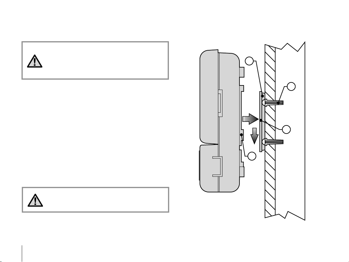
NOTE: The SRC is not water or weather resistant.
The controller must me installed indoors or in a
protected area. If outdoor installation is desired,
the MPC (an optional outdoor mounting enclosure)
is available.
1. Select a location as close as possible to a standard electrical outlet,
one that is not controlled by a light switch. The location should be
protected from moisture and direct sunlight.
2. Remove the mounting bracket (A) from the back of the controller
housing by pulling the bracket down and slightly away from
the unit.
3. Place the mounting bracket slightly below eye level. Using the hole
at the top and the slide cutout at the bottom, secure the bracket with
the 1" (25mm) screws (B) provided. Note: Install screw anchors if
attaching mounting bracket to drywall or masonry.
4. Align slotted openings on back of controller housing (C) with rails
on the mounting bracket (D). Gently slide the controller down into
position on the bracket.
5. Secure controller in place by installing a screw through the lower
central mounting hole.
Do not plug transformer into power source until
the controller is mounted and all valves have
been connected.
4
Page 9
MOUNTING THE CONTROLLER OUTDOORS (MPC ENCLOSURE) ..................................
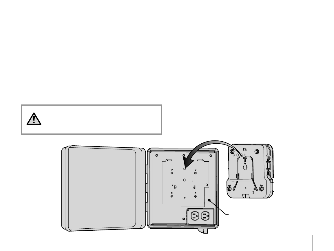
MPC Enclosure
1. The MPC enclosure has 4 mounting holes, 3 along the top of the
unit, and one at the bottom center. These may be punched out in
order to secure the unit to a wall.
2. Remove the door and mounting plate from the SRC. Attach the SRC
to the MPC by inserting the mounting tab on the mounting plate
inside the MPC, into the keyhole in the back of the SRC. Slide down
the SRC until it locks into place. You may use an optional mounting
screw if desired.
3. Field wiring should be routed through the large center hole in the
enclosure using an appropriate conduit and conduit fitting.
NOTE: Installation of the primary voltage
wires should be done by a licensed electrical
professional. Improper installation may result in
fire or shock hazard.
4. With primary power off, the primary power wires should be routed
through an agency approved electrical conduit and electrical
conduit fitting into the duplex outlet wiring enclosure and attached
to the outlet.
5. The transformer may then be plugged into the duplex outlet.
6. Attach the two wires coming out of the transformer to the two screw
slots on the SRC labeled “AC.”
7. Primary power may now be turned on.
5
Page 10
7
AC AC R RS C MV 1 2 3 4 5 6FUSE 0.75A
9 V Battery
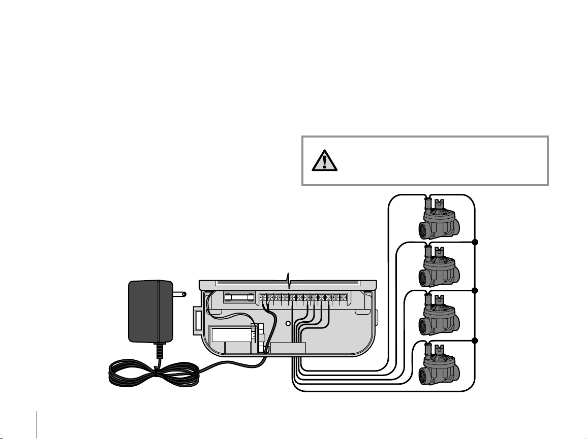
Valve Common Wire
Connect the Two
Transformer Wires to
the Two AC Terminals
Transformer
Valve 1
Valve 2
Valve 3
Valve 4
Valve Wires
CONNECTING VALVES AND TRANSFORMER ....................................................................
1. Route control wires between control valve location and controller.
Typically it is recommended that an 18 AWG multi-wire sprinkler
connection cable be used. This type of connection is insulated for
burial and is color-coded to help keep track of your connections.
2. At the valves, attach the common wire to either solenoid wire of the
valve. This is most commonly the white colored wire. Attach a
separate control wire to the remaining solenoid wire and make a
note of the color corresponding to each valve and the watering
station it controls.
3. Secure the wires with a waterproof wire connector to protect
the connection.
4. Open hinged wiring compartment door to access the terminal strip
area shown in the diagram.
5. Route the valve wires through the large opening on the base of the
cabinet or through inch conduit if installed. Strip inch of
insulation from ends of all wires.
6. Secure the white valve common wire to the screw on the terminal
marked C. With the valve common wire connected, connect the
color-coded wires from the valves to their appropriate station
numbers and tighten the screws.
7. Route transformer cable through the small hole in the bottom of the
cabinet and connect the wires to the two screws marked AC.
Do not plug transformer into power source until
the controller is mounted and all valves have been
connected.
6
Page 11

AC AC R RS C MV 1 2 3 4 5 6FUSE 0.75A
9 V Battery
Battery Compartment
Wire Clip Spare Fuse Holder
AC AC R RS C MV 1 2 3 4 5 6FUSE 0.75A
9 V Battery
Valve Common Wire
Valve 1
Valve 2
Valve 3
Valve 4
Valve Wires
Master Valve
Master Valve Wire
CONNECTING THE BATTERY.................................................................................................
The battery allows you to program the SRC Controller without having AC
power available. However, the battery will not be able to activate any
of the station valves. Electrical power must resume before watering will
continue. The SRC has non-volatile memory which retains all program
information in the event of a power outage.
CONNECTING A MASTER VALVE..........................................................................................
NOTE: Complete this section only if
you have a master valve installed. A
master valve is a normally closed valve
installed at the supply point of the main
line that opens only when the automatic
system is activated.
1. At the Master Valve, attach the common wire to either
solenoid wire of the valve. Attach a separate control wire
to the remaining solenoid wire and make a note of the
color corresponding to the master valve.
2. Route these wires to the controller the same way as the
station valves. The white common wire will still go to the
screw slot marked C. The additional wire coming from
the master valve will go in the screw slot marked MV.
7
Page 12

9
15' Minimum (4.5 m)
PSR Series
Pump Start Relay
To Pump
CONNECTING A PUMP START RELAY.................................................................................
NOTE: Complete this section only if you have a
pump start relay installed. A pump start relay
is an electronic device that uses a current from the
controller to actuate a separate electrical circuit to
energize a pump to provide water to your system.
The controller should be mounted at least 15 feet (4.5m) away from both
the pump start relay and the pump. When a pump start relay comes on it
sends out surges that may potentially cause damage to a controller that
is mounted to close. When a pump is to be operated by the controller, a
pump start relay must be used. Hunter offers a full range of pump start
relays for most applications.
1. Route a wire pair from the pump relay into the controller housing.
2. Connect common wire to the screw slot C (Common) and the
remaining wire from the pump relay to the MV screw slot.
Relay current draw must not exceed .35 Amps. Do not connect
controller directly to pump – damage to controller can result.
8
Page 13

AC AC R RS C MV 1 2 3 4 5 6FUSE 0.75A
9 V Battery
Sensor Wire to Common
Valve Common to RS
Hunter Weather Sensor
Connect Common to
this Terminal when
using Rain Sensor
Connect Rain Sensor Wires
to These Two Terminals
Sensor Wire to Weather Sensor
CONNECTING A WEATHER SENSOR ...................................................................................
A Hunter Mini-Clik® rain sensor or other type of interrupt weather sensor
can be connected to the SRC. The purpose of this sensor is to stop
watering when precipitation is sufficient. The sensor connects directly
to the controller and allows you to easily override the sensor by using
the RUN (BYPASS SENSOR) position on the dial.
1. Route the wires from the rain sensor up through the same opening
used for valve wiring.
2. Connect one wire to the RS terminal and the other to the C terminal.
3. Connect the valve common from the field to the RS terminal.
Note: If a pump relay is being used, the pump relay common must
also be connected to the RS terminal.
A weather sensor shuts off your system during rainy
weather – saving water. Ask your installer for more
information on this device.
9
Page 14

11
AC AC R RS C MV 1 2 3 4 5 6
White
Blue
Red
CONNECTING AN SRR OR ICR REMOTE CONTROL (NOT INCLUDED) .........................
1
/2" Thread
To
Controller
Pre-assembled Assembled
Controller
Receiver
Outdoor Installation
(Temporary Connection
of Receiver Only)
Indoor Installation
The Hunter SRC is remote-ready for use with the SRR or ICR remote
control system. The remote makes it possible for contractors and
end-users alike to operate an system without having to walk back and
forth to the controller.
To utilize the SRR or ICR Remote Control System you must install the
SmartPort® outlet.
1. Install a " female threaded
PVC “Tee” in the field
wiring conduit (PVC pipe)
approximately 12" below
the SRC.
2. Feed the red, white, and blue
wires of the harness through
the base of the “Tee” and into
the wiring compartment as
shown in Figure 1.
3. Screw the harness housing
into the “Tee” as shown
in Figure 1.
4. Access the terminal strip area and attach the red wire to the left AC
screw slot, attach the white wire to the next AC screw slot and attach
the blue wire to the screw slot marked “R”.
Figure 1
NOTE: Any extension of the wiring on the remote
harness may result in an error message in the
controller display and possible malfunction of the
remote unit due to radio interference. In some
situations, lengthening of the harness may work
fine, in others it may not work at all (it is site
specific). In either case, extending the wiring
harness should be done using shielded cable to
minimize the possible effects of electrical noise.
For easiest installation, order a new Hunter SRRSCWH SmartPort® wiring harness with a full 25 feet
of shielded cable.
The wiring harness is now ready for remote control use. Please refer to
the SRR or ICR owner manual for further information or contact your
local Hunter distributor for ordering information.
10
Page 15

CONNECTING TO THE HUNTER IRRIGATION MANAGEMENT AND
MONITORING SYSTEM™ (Not Included).............................................................................
With the IMMS™, automatic irrigation systems at multiple sites or multiple controllers at a single site can be programmed for functions that would
typically be handled directly at each controller. Scheduling of days to water, run times, start times, cycle and soak operations and more can now be
done from a single computer at a desk miles away from the actual installation. In addition, scheduled operation of non-irrigation components also in
use at these sites – e.g., lighting systems at athletic fields, fountains at shopping centers – as well as pumps and sensors can also be programmed
and monitored from a single central location. A key function of the IMMS is its ability to monitor changing conditions. With the aid of such options as
flow sensors, rain sensors and other weather-sensing devices, the IMMS can receive reports on the current condition at every site it is linked with and
then respond with the necessary adjustments should any of those conditions go beyond the limits that have been defined. It’s able to team with any
or all of the standard automatic controllers in the Hunter line-up, from the SRC to the Pro-C to the ICC. Plus, it’s a system that’s easy and affordable
to upgrade, making it possible to accommodate an expanding network of controllers. For more information on the IMMS software, contact your local
Hunter dealer.
POWER FAILURES ...................................................................................................................
Due to the possibility of power failures, the controller has non-volatile memory to preserve the program indefinitely. If no 9-volt batter y is installed,
the controller will freeze time when the power goes out and resume, keeping time after power has been restored. If a battery is installed, the 9-volt
battery backup will keep time so the clock and calendar will be intact for several days.
11
Page 16

13
RUN
NEXT
PROGRAM
START
TIMES
STATION RUN TIME
YEAR
MONTH
DA
Y
RUNNING
AM
PM
24 HR.
SUN MON TUES WED
THUR
FRI SAT EVEN/ODD
SYSTEM OFF
RUN (BYPASS SENSOR)
SET DAYS TO WATER
MANUAL - SINGLE STATIO
N
MANUAL - ALL STAT
IONS
SET CURRENT DATE/TIME
SET WATERING ST
ART TIMES
SET STATION RUN TIME
S
Valve 1 – Activates Station 1 – Rotors water front
yard lawn
Valve 2 – Activates Station 2 – Sprays water side
lawn and bubblers water flowers
Valve 3 – Activates Station 3 – Rotors water back
yard lawn
Valve 4 – Activates Station 4 – Bubblers water garden
Valve 5 – Activates Station 5 – Sprays water side lawn
and bubblers water flowers
Valve 6 – Activates Station 6 – Sprays water front
corner lawn
Valve 1
Station 1
Station 2
Station 3
Station 6
Valve 2 Valve 3
Valve 5
®
®
SRC Controller
Station 5
Valve 4Valve 6
Station 4
®
®
®
®
SPRINKLER SYSTEM FUNDAMENTALS.............................................................................
There are three main components that are involved with all automatic
sprinkler systems that are made today. They are the controller, control
valves, and the sprinklers .
The controller is what makes the whole system operate efficiently.
It is technically the brain of the entire system, instructing the valves
when to supply water to the sprinklers and for how long to do so. The
sprinklers, in turn, will direct the water towards the surrounding plants
and lawn.
The valve controls a group of sprinklers called a watering station. These
stations are laid out in a fashion according to the type of plant life that
exists there, the locations of the plant’s, and the maximum amount of
12
water that can be pumped to the location. Each valve is connected via
wire to the terminal strip area inside of the controller. Here the wire is
connected to a number that corresponds to the valves station number.
The controller will operate the valves in order, only one at a time. When
a valve has completed it’s watering; it will switch to the next station that
has been programmed. This process is called the watering cycle. The
information pertaining to the watering times of the individual stations
and how often watering occurs is called a program.
Page 17

Program
Begins at
6:00 AM
12
6
39
12
6
39
12
6
39
Program
Ends at
6:50 AM
Station 1
Station 2
Station 3
®
®
®
®
®
®
Sprinklers at
Station 1 begin to
water at 6:00 AM
Sprinklers at
Station 1 turn off
at 6:15 AM
Sprinklers at
Station 2 begin to
water at 6:15 AM
Sprinklers at
Station 2 turn off
at 6:30 AM
Sprinklers at
Station 3 begin to
water at 6:30 AM
Sprinklers at
Station 3 turn off
at 6:50 AM
PROGRAMMING FUNDAMENTALS .....................................................................................
For the controller and it’s selected program to operate automatically,
there are three components that must exist: When to water (or Watering
Start Times), how long to water (or Station Run Times), what day of the
week to water (or Days to Water).
We have included an example that will better illustrate the operation
of a program. Let’s say you have a program start time set for 6:00 A M.
Stations 1 and 2 are going to have a run time of 15 minutes and station 3
is set for 20 minutes. Please note that stations 4, 5 and 6 have not been
included in this program, we will water them on separate programs.
Going back to our previous example, at 6:00 AM the controller will activate
the watering cycle. The sprinklers on station 1 will run for 15 minutes
and then automatically shut off. The controller will automatically activate
station 2 sprinklers. These sprinklers will also run for 15 minutes and
then shut off. Then, watering on station 3 will begin automatically. The
sprinklers will turn on for 20 minutes and shut off automatically. Since
no times were programmed for stations 4, 5 and 6, the controller skips
them. This will conclude the program and end the water cycle at 6:50 AM.
As shown in the above example, only one program start time was
required to run the three different stations. The controller automatically
moves to the next station without the need for additional start times.
We realize that many consumers will have variations in their plant
watering needs, so at Hunter we equipped the SRC with three different
programs A, B, and C. These programs are completely independent
of each other and give you the ability to have three coexisting timers in
one controller.
For example, using more than one program would enable you to water
on odd days for lawn stations 1, 2, and 3 on program A, station 4 to soak
the flowers every day on program B, and station 5 and station 6 to water
on even days on program C. However, it is not absolutely necessary
to use this feature. Most homes and businesses can have all stations
adequately watered on one program with the other programs turned off
for future use.
13
Page 18

15
CREATING A WATERING SCHEDULE ...................................................................................
For most consumers, it is much easier to plan your specific watering
schedule onto paper before actually programming the information
into the controller. It’s also handy to have a written record of your
programming information for easy reference.
There are some guidelines that should followed when determining
when and how long to water. These factors are, the soil type, the part
of the landscape being watered, weather conditions, and the types of
sprinklers being used. Since there are so many different variables that
can determine your individual watering schedule; it is impossible to give
an exact schedule to follow. However, we have included some guidelines
to help you get started.
It is usually good to water one or two hours before
sunrise. Water pressure will be at optimum levels
during the early morning and the water can soak
into the roots of the plants while evaporation is
minimal. For most plants, watering during midday
or in the evening may cause plant damage or
possibly mildew.
Keep an eye out for evidence of under- or overwatering. Over-watering is most commonly
indicated by pools of water that take a long time
to soak in or evaporate, while under-watered
landscapes will show signs of discoloring and
dryness. Make programming changes immediately
when evidence is present.
HOW TO FILL OUT THE WATERING SCHEDULE FORM ....................................................
Be sure to use a pencil when filling out this form. By using the included
example and the information below, you should have all the information
you need to construct your personal water schedule.
Station Number and Location – Identify the station number, location
and the type of plant that is being watered.
Watering Day – Identify whether you want to use a calendar day or an
odd or even day schedule. For a calendar day schedule circle the day of
the week in which watering is desired. For a odd or even day schedule,
simply mark the corresponding box.
Program Start Times – Indicate the time of day that the program will
begin. Each program can have 1 to 4 start times. However, one start time
can run an entire program.
Station Run Time – Indicate the run time (1 to 99 minutes) for each
station. Write “OFF” for any station that you do not want to operate in
the program.
Keep this schedule in a safe place for quick reference later, rather than
scrolling through program information on the controller.
14
Page 19

WATERING SCHEDULE FORM (Example)............................................................................
PROGRAM A PROGRAM B PROGRAM C
CALENDAR
ODD/EVEN
WATERING
DAY
SCHEDULE
SU MO TU WE TH FR SA SU MO TU WE TH FR SA SU MO TU WE TH FR SA
ODD EVEN ODD EVEN ODD EVEN
LOCATION
1
2
3
4
5
6
7
8
9
STATION
ZONE RUN TIME ZONE RUN TIME ZONE RUN TIME
1
2
3
4
PROGRAM
START TIMES
Front Lawn
Side Lawn
Back Lawn
Flowers
Garden
Front Corner
15
15
20
Off
Off
Off
Off
Off
Off
15
Off
Off
Off
Off
Off
Off
20
60
6:00 AM
Off
Off
Off
8:00 AM
Off
Off
Off
5:00 AM
Off
Off
Off
X
X XXX X X X
X
15
Page 20

17
WATERING SCHEDULE FORM...............................................................................................
PROGRAM A PROGRAM B PROGRAM C
CALENDAR
ODD/EVEN
WATERING
DAY
SCHEDULE
SU MO TU WE TH FR SA SU MO TU WE TH FR SA SU MO TU WE TH FR SA
ODD EVEN ODD EVEN ODD EVEN
LOCATION
1
2
3
4
5
6
7
8
9
STATION
ZONE RUN TIME ZONE RUN TIME ZONE RUN TIME
1
2
3
4
PROGRAM
START TIMES
16
Page 21

PROGRAM
START
TIMES
STATION RUN TIME
YEAR
MONTH
DA
Y
RUNNING
AM
PM
24 HR.
SUN MON TUES WED
THUR
FRI SAT EVEN/ODD
PROGRAM
START
TIMES
STATION RUN TIME
YEAR
MONTH
DAY
RUNNING
AM
PM
24 HR.
SUN MON TUES WED
THUR
FRI SAT EVEN/ODD
PROGRAM
START
TIMES
STATION RUN TIME
YEAR
MONTH
DAY
RUNNING
AM
PM
24 HR.
SUN MON TUES WED
THUR
FRI SAT EVEN/ODD
PROGRAM
START
TIMES
STATION RUN TIME
YEAR
MONTH
DAY
RUNNING
AM
PM
24 HR.
SUN MON TUES WED
THUR
FRI SAT EVEN/ODD
SET CURRENT
DATE/ TIME
PROGRAMMING THE CONTROLLER ...................................................................................
The SRC Controller is easy to program. The easy to understand dial
design allows you to step through the process of programming and
activate manual watering with a twist of the wrist.
The SRC display shows time and day when the controller is idle.
The display changes when the dial is rotated to indicate the specific
programming information to enter. When programming, the flashing
portion of the display can be changed by pressing the or buttons.
To change something that is not flashing, press the button until the
desired field is flashing.
The SRC also provides a reference label that is attached to the inside of
the controller door (no more lost or misplaced instructions!). And, extra
space is provided to write in sprinkler station location information.
A full three programs, each with the ability to have four daily start times,
permit plants with different watering requirements to be separated
on different day schedules. Multiple start times permit morning,
afternoon, and evening watering, perfect for the establishment of new
lawns and thirsty annual flowers. A built-in 365 day calendar clock
accommodates odd/even watering restrictions without requiring
monthly reprogramming. Or just simply designate the days of the week
you want to water. The SRC makes it easy.
NOTE: A basic programming rule is that whatever
symbol or character is flashing will be the item
programmed. For instance, if the hour is flashing
when setting the time, the hour can be changed or
programmed. For illustration purposes, flashing
characters are in GRAY type.
Setting the Date and Time
1. Turn the dial to the
SET CURRENT DATE/TIME
position.
2. The current year will be
flashing in the display:
Use the or button to
set the year. After setting the
correct year, push the to
proceed to setting the month.
3. The month and day will be in
the display: The month will
be flashing. Use the or
button to set the month.
Push the to proceed to
setting the day.
4. The day will be flashing:
Use the or button to set
the day of the month.
(The day of the week is
automatically indicated by an
arrow in the bottom of display
pointing to the day.) Push the
button to proceed to setting
the time.
5. The time will be displayed,
and an arrow will be flashing
on AM. Press the or
buttons to select AM, PM, or
24 HR. Press the to proceed
to setting the hours.
17
Page 22

19
PROGRAMMING THE CONTROLLER (Continued)..............................................................
PROGRAM
START
TIMES
STATION RUN TIME
YEAR
MONTH
DA
Y
RUNNING
AM
PM
24 HR.
SUN MON TUES WED
THUR
FRI SAT EVEN/ODD
PROGRAM
START
TIMES
STATION RUN TIME
YEAR
MONTH
DAY
RUNNING
AM
PM
24 HR.
SUN MON TUES WED
THUR
FRI SAT EVEN/ODD
A
B
C
1
2
3
4
PROGRAM
START
TIMES
STATION RUN TIME
YEAR
MONTH
DAY
RUNNING
AM
PM
24 HR.
SUN MON TUES WED
THUR
FRI SAT EVEN/ODD
SET WATERING
START TIMES
6. Hours will be flashing.
Press the or button
to change the hour shown
on the display. Press the
to proceed to setting the
minutes.
7. Minutes will be flashing.
Use the or button to
change the minutes shown on
the display. The date, day and
time have now been set and
the dial may be returned to the
RUN position.
Eliminating a Program Start Time
With the dial set to the SET WATERING START TIMES position, push the
or button until you reach 12:00 AM (Midnight). From here push the
button once to reach the OFF position.
NOTE: One start time will activate all stations
sequentially in that program. This eliminates the
need to enter each station’s start time. Multiple
start times in a program can be used for separate
morning, afternoon, or evening watering cycles.
Setting Watering Start Times
1. Turn the dial to the SET
WATERING START TIMES
position.
2. The factory preset is set on
program A. If necessary, you
can select program B or C by
pressing the button.
3. Use the or button to
change the start time.
(The start times advance in
15 minute increments.)
Hold either button down for 1
second to change times rapidly.
4. Press the button to select the
next start time, or press for
the next program.
18
NOTE: If a program has all four-start times turned
off, then that program is off. (All other program
details are retained). Because there are no start
times, there will be no watering with that program.
This is a convenient way to stop watering on one
program only without turning the dial to the OFF
position.
Page 23

SET STATION RUN TIMES
A
B
C
1
2
3
4
PROGRAM
START
TIMES
STATION RUN TIME
YEAR
MONTH
DAY
RUNNING
AM
PM
24 HR.
SUN MON TUES WED
THUR
FRI SAT EVEN/ODD
Setting Station Run Times (Length of Watering for Each Area)
SET DAYS TO WATER
A
B
C
1
2
3
4
PROGRAM
START
TIMES
STATION RUN TIME
YEAR
MONTH
DAY
RUNNING
AM
PM
24 HR.
SUN MON TUES WED
THUR
FRI SAT EVEN/ODD
1. Turn the dial to the SET
STATION RUN TIMES position.
2. The display will show the last
program selected (A, B, or C)
the station number selected,
and the run time for that
station will be flashing. You
can switch to another program
by pressing the button.
3. Use the or button to
change the station run time on
the display.
4. Press the button to advance
to the next station.
5. Repeat steps 3 and 4 for each station.
6. You can set station run times anywhere from 0 to 99 minutes.
7. You can move between programs while staying on the same station.
However, it is recommended that one program is completed before
going on to the next program.
NOTE: Jumping between programs can be confusing
and may result in program entry errors.
Setting Days To Water
1. Turn the dial to SET DAYS
TO WATER.
2. The display will show the last
program selected (A, B, or C).
You can switch to another
program by pressing the
button.
3. The controller will display currently programmed active day
schedule information. This dial position provides different watering
options: choose to water on specific days of the week, or choose
to water only on odd days or even days. Each program can operate
using only one type of water day option.
Selecting Specic Days of the Week to Water
1. With the arrow cursor on a
specific day (the cursor always
starts with Sunday), press
the button to activate a
particular day of the week to
water. Press the button
to cancel watering for that day. After pressing a button the cursor
automatically advances to the next day.
2. Repeat step 1 until all desired days have been selected. The selected
days arrows will show on the display to indicate their status as ON.
The last solid arrow is the last day of watering for that program.
19
Page 24

21
PROGRAMMING THE CONTROLLER (Continued)..............................................................
A
B
C
1
2
3
4
PROGRAM
START
TIMES
STATION RUN TIME
YEAR
MONTH
DAY
RUNNING
AM
PM
24 HR.
SUN MON TUES WED
THUR
FRI SAT EVEN/ODD
RUN (BYPASS SENSOR)
MANUAL - SINGLE
STATION
RUN
SYSTEM OFF
Selecting Odd or Even Days
This feature will use a numbered
day of the month for watering
instead of specific days of the
week (Odd days 1st, 3rd, 5th, etc.;
Even days 2nd, 4th, 6th, etc.)
1. Press the button until the arrow cursor is above either EVEN or
ODD on the display.
2. Press the button to select or the button to cancel either Odd
Days or Even Days. The previous selected days of the week will
revert to active if Odd Days or Even Days is cancelled.
Run
After programming is complete, turn the dial
to RUN to enable automatic execution of all
selected programs and start times. Watering
will not occur unless dial is in the RUN or
RUN (SENSOR BYPASS) position.
20
NOTE: The 31st of any month and February 29 are
always “off” days if Odd watering is selected.
Weather Sensor Bypass
With this built-in feature, there is
no need for an additional manual
bypass switch when using rain
sensors (the SRC works with the
Hunter Mini-Clik®, plus some
other rain, wind or freeze sensors on the market today).
If the sensor is preventing system operation, just turn the dial to
RUN (BYPASS SENSOR) and the weather sensor will be overridden.
System Off
Valves currently watering will be
shut off after the dial is turned
to the SYSTEM OFF position for
two seconds. All active programs
are discontinued and watering
is stopped. To return controller
to normal automatic operation,
simply return dial to RUN position.
Manually Run a Single Station
1. Turn dial to the MANUALSINGLE STATION position.
2. Station run time will flash in
the display. Use the button
to move to the next station.
You may use the or
button to select the amount of
time for a station to water.
3. Turn the dial clockwise to the RUN position to run the station (only
the designated station will water, then the controller will return to
automatic mode with no change in the previously set program).
Page 25

MANUAL - ALL
STATIONS
Manually Run All Stations
1. Turn dial to MANUAL-ALL
STATIONS.
2. You can select program A, B, or
C by pressing the button.
3. Press the button until desired
starting station is displayed.
4. Station run time will flash in the display. Use the or buttons
to select the amount of run time for the station to water.
5. Use the button to move to the next station.
6. Repeat steps 3 and 4 to customize each station.
7. Press the button until you reach the station that you would like
watering to begin.
8. Return dial to RUN (custom program will water, then controller
will return to automatic mode with no change in the previously
set program).
NOTE: The station that is on the display when you
turn the dial to RUN will be the first station to
run. The controller will then proceed to water in
sequential order only. It will not water previous
stations. Example: If you turn the dial to RUN with
the display reading station 3. The controller will
water stations 3 to 9 in the program, but not return
to stations 1 and 2.
One Touch Manual Start and Advance
You can also activate all stations to water without using the dial.
1. Hold down the button for 2 seconds.
2. This feature automatically defaults to program A. You can select
program B or C by pressing the program.
3. The station number will be flashing. Press the button to scroll
through the stations and use the or buttons to adjust the
station run times. (If no buttons are pressed during step 2 or 3, the
controller will automatically begin program A.)
4. Press the button to scroll to the station you wish to begin with.
After a 2 second pause, the program will begin.
This feature is great for a quick cycle when extra watering is needed or if
you would like to scroll through the stations to inspect your system.
Clearing the Controller's Memory/Reseting the Controller
If you feel you have misprogrammed the controller, there is a process
that will reset the memory to factory defaults and erase all programs and
data that has been entered into the controller.
1. Remove all power (unplug transformer and remove battery) and wait
at least 1 minute.
2. Press and hold down the , and buttons.
3. Restore power to the controller.
4. Release the , and buttons.
21
Page 26

23
TROUBLESHOOTING GUIDE ..................................................................................................
PROBLEM CAUSES SOLUTIONS
Display indicates irrigation but station
does not water.
Display is blank.
Display is blank with AC power to terminal
and with a new battery.
Time of day display is blinking.
The display reads “ERR”.
The display reads “No AC”
Fuse is blown. Replace fuse.
Faulty or miswired valve Check valve and valve wiring.
Faulty pump or pump relay. Check pump and pump relay.
Replace if defective.
No water pressure to supply. Turn on main system water system.
No AC power reaching controller. Verify AC power and wiring. Correct any
errors. Check transformer output.
Controller may be damaged by power surge. Call dealer.
Unit has just been powered up for the
rst time.
Extended power outage has occurred that
has drained backup battery.
Short power outage has occurred but
backup battery is dead.
Electrical noise is entering the system,
through the smart port wiring harness.
There is no AC power present. Check to make sure power is on. Check to
Set time/date.
Replace battery and reprogram current time.
Replace battery and reprogram current time.
Check the SmartPort™ wiring harness.
If the wires were extended then they will
need to be replaced with shielded cable.
Contact your local distributor for information
on shielded cable.
see if transformer is properly installed.
22
Page 27

PROBLEM CAUSES SOLUTIONS
Rain Sensor does not suspend irrigation.
Frozen Display
Automatic irrigation does not start at
start time and controller is not in the
system off mode.
Valve will not turn on.
Fuse blown/Fuse blows repeatedly.
Controller waters the same area more than
one time/Controller cycles continuously.
Rain sensor is defective or miswired. Verify operation of sensor and proper wiring.
Rain sensor is in the RUN (BYPASS
Return dial to the RUN position.
SENSOR) position.
Power surge. Unplug transformer, remove battery,
wait several seconds, repower and
reprogram controller.
AM/PM of time of day not set correctly. Correct AM/PM of time of day.
AM/PM of start time not set correctly. Correct AM/PM of start time.
Start time is disabled (Set for Off). Set start time. See "Setting Start Times"
(page 17).
Rain sensor is preventing operation. Turn dial to RUN (BYPASS SENSOR).
Controller is not receiving AC power. Check AC connections.
Short in wire connections (blown fuse). Check wiring for short or faulty wire
connections.
Bad solenoid Replace solenoid.
Short in valve wiring. Check valve wiring.
Shorted solenoid. Check valve solenoids, replace if defective.
Too many start times entered in program
(user error).
One start time activates a complete cycle.
See "Setting Start Times" (page 17).
23
Page 28

25
FREQUENTLY ASKED QUESTIONS .......................................................................................
1. WHY DOES MY SYSTEM CONTINUE TO CYCLE THROUGH OVER
AND OVER?
You may have too many start times entered. Only one start time
is needed to run a program. See section titled “Setting Watering
Start Times.”
2. DO I NEED A START TIME FOR EVERY STATION?
No! You only need one start time per program. The program runs
sequentially, so the proceeding station will automatically start when
the previous station is finished, no need for additional start times.
Multiple start times are utilized when you desire to water an entire
program more that once in a 24-hour period.
3. WHY ARE THERE THREE DIFFERENT PROGRAMS (A, B, AND C)?
These three programs exist for a variety of reasons. Since
customers needs vary from each location, it is important to make
sure that even the largest landscapes can be properly irrigated.
Most consumers can fulfill there needs with a single program and a
single start time, but others who have a variety of different plant life
may need more than one program and several start times. See the
section “Programming Fundamentals” for more information.
4. WHY IS THE ARROW FLASHING ON SUNDAY EVERY TIME I TURN
THE DIAL TO “SET DAYS TO WATER”?
The arrow always flashes on Sunday when you turn the dial to this
position. When finished setting the days you want, turn the dial to
any position. When you go back to SET DAYS TO WATER you will see
the solid arrows lit over the days you have chosen.
24
5. AN INDIVIDUAL STATION WON’T SHUT OFF, WHAT DO I DO?
When one particular station is stuck on, you want to shut off the
controller by turning the dial to the off position. If the station is
still running, you will need to shut off the main water supply to
the sprinkler system. Most likely there is a valve stuck open,
caused by debris in the valve. A loose solenoid or loose valve cap
may also be the problem. Check these connections or call your
contractor for assistance.
6. WHAT IS A MINI-CLIK® RAIN SENSOR AND DO I NEED ONE FOR MY
SYSTEM?
The purpose of the Mini-Clik® rain sensor is to discontinue watering
when there is sufficient precipitation to take care of your watering
needs. The sensor is a great addition to any system, whether you
need it or not depends upon several things: The frequency and
amount of rain in your area and how often you are away from your
home are probably the most important. If your area is subject to
random or high amounts of precipitation, or your away from home
so frequently that it keeps you away from monitoring your system,
then the sensor will help you to regulate your system and save
water. Generally, a sensor is a low cost addition to a system and will
pay for itself in water savings in a single season.
7. WHAT IS THE SRR AND DO I NEED ONE FOR MY SYSTEM?
The SRR (Simple Reliable Remote) is a simple four-button control
that gives you the ability to start, stop, or alter the watering cycle
from as much as 450 feet away from the controller. It is very
convenient when doing repairs, maintenance, and winterization
on your system without having to walk back and forth between the
stations and the controller. Even if you don’t use it for maintenance,
it is useful for starting or stopping a manual irrigation cycle without
walking back and forth to the controller.
Page 29

SPECIFICATIONS .....................................................................................................................
Operating Specications
• Station Run Time: 0 to 99 minutes in 1-minute increments
• Start Times: 4 per day, per program, for up to 12 daily starts
• Watering Schedule: 7-day calendar or odd-even programming with 365-day clock/calendar
Electrical Specications
• Transformer Input: 120VAC, 60Hz (230VAC, 50/60Hz International Use)
• Transformer Output: 26VAC, .75 amps
• Station Output: 24VAC, .35 amps per station
• Maximum Output: 24VAC, .75 amps (includes Master Valve Circuit)
• Battery Backup: 9-volt alkaline battery (not included)
• Three Programs: A, B, and C
• Non-Volatile Memory
Dimensions
• Overall Height: 8" (21 cm)
• Width: 8" (6 cm)
25
Page 30

27
INFORMATION ABOUT YOUR SPRINKLER SYSTEM........................................................
Date of Installation: _________________________________________________________________________________________
Contractor Installing System:__________________________________________________________________________________
Address:__________________________________________________________________________________________________
_________________________________________________________________________________________________________
Phone: ___________________________________________________________________________________________________
Location of Control Valves: ___________________________________________________________________________________
_________________________________________________________________________________________________________
Location of Weather Sensor: __________________________________________________________________________________
_________________________________________________________________________________________________________
Location of Main Water Supply Shutoff: _________________________________________________________________________
_________________________________________________________________________________________________________
26
Page 31

NOTES........................................................................................................................................
27
Page 32

FCC NOTICE...............................................................................................................................
This controller generates radio frequency energy and may cause interference to radio and television reception. It has been type tested and found to
comply with the limits for a Class B computing device in accordance with the specifications in Subpart J of Part 15 of FCC Rules, which are designed to
provide reasonable protection against such interference in a residential installation. However, there is no guarantee that interference will not occur in a
particular installation. If this equipment does cause interference to radio or television reception, which can be determined by turning the equipment off
and on, the user is encouraged to try to correct the interference by one or more of the following measures:
• Reorient the receiving antenna
• Move the controller away from the receiver
• Plug the controller into a different outlet so that controller and receiver are on different branch circuits
If necessary, the user should consult the dealer or an experienced radio/television technician for additional suggestions. The user may find the
following booklet prepared by the Federal Communications Commission helpful: “How to Identify and Resolve Radio-TV Interference Problems.”
This booklet is available from the U.S. Government Printing Office, Washington, D.C., Stock No. 004-000-00345-4 (price – $2.00 postpaid).
Hunter Industries Incorporated • The Irrigation Innovators © 2002 Hunter Industries Incorporated
1940 Diamond Street • San Marcos, California 92069
www.HunterIndustries.com
P/N 709686 LIT-185 12/02
 Loading...