

Page 1

®
PROC
Residential and Light Commercial
Irrigation Controller
PC Series
Modular Controller
Indoor/Outdoor Models
Owner’s Manual and
Installation Instructions
Page 2

Table of Contents
Introduction and Installation
3 Specications
4 Pro-C Components
8 Mounting the Controller to a Wall
9 Connecting AC Power
10 Installing Station Modules
11 Connecting Station Wires
12 Connecting the Battery
13 Connecting a Master Valve
14 Connecting a Pump Start Relay
15 Connecting a Hunter “Clik” Weather Sensor
17 Connecting a Hunter Remote
19 Connecting to the Hunter Solar Sync
®
Programming the Controller
20 Setting the Current Date and Time
21 Setting Program Start Times
22 Setting Station Run Times (Length of Watering
for Each Area)
23 Setting a Watering Schedule
25 Options for Running Your Irrigation System
27 Using the Pro-C to Operate Outdoor Lighting
Advanced Features
29 Set Pump/Master Valve Operation
29 Programmable Rain O
29 Setting Specic Days O
Hidden Features
30 Program Customization
30 Programmable Delay Between Stations
31 Programmable Sensor Override
32 Total Run Time Calculator
32 Easy Retrieve™ Program Memory
33 Solar Sync Delay
34 Cycle and Soak
36 Hunter Quick Check™
36 Clearing Controller’s Memory/Resetting Controller
36 Winterizing Your Irrigation System
Troubleshooting Guide
37 Problems, Causes and Solutions
Quick Ch eck and Easy Ret rieve are trade marks of Hunte r Industries , Inc.
Pro-C , Solar Sync, Rai n-Clik, Freeze -Clik and Smar tPort are reg istered trad emarks of
Hunter Industries, Inc.
Page 3

Specications
Operating Specications
• Stati on Run Time: 1 minute to 6 hour s on programs
A, B, and C
• Star t Times: 4 per day, per prog ram, for up to 12 daily sta rts
• Watering Schedule: 7-day calend ar, in terval watering up
to a 31-day inter val or true odd or e ven day programming ,
made possi ble by the 365-day clo ck/calenda r
Electrical Specications
• Transformer Input: 120 VAC, 60 hz
(230 VAC, 50/60 hz Inter national Use)
• Transformer Output: 24 VAC, 1 Amp
• Station Output: 24 VAC, 0.56 amps per st ation
• Maximum Output : 24 VAC, 0.84 amps
(includes Master Valve Circuit)
• Battery: 9-volt alka line battery (not incl uded) used
only for no n-AC program ming, the non-volatil e memory
maintains program inform ation
• Bat tery, front panel, int ernal CR2032 Lithium f or
real-time clock
Cabinet Dimensions
Height: 9 " (23 cm)
Width: 10" (2 1.5 cm)
Depth: 4.5" ( 10.9 cm)
Outdoo r cabinet is NEMA 3R, IP4 4 rated.
Default Settings
All stations are set to zero run time. This controller has a
non-volatile memory that retains all entered program data
even during power outages, without need for a battery.
Cleaning
Clean only with cloth dampened with mild soapy water.
3
Page 4
Pro-C Components
A
4
B
Page 5
Pro-C Components (continued)
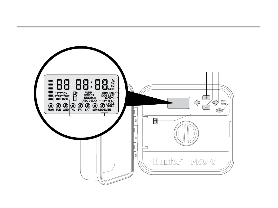
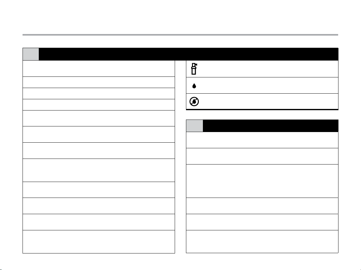
LCD Display
A
Main Display
①
Year Identies current calendar year
②
Month Identies current calendar month
③
Day Identies current calendar day
④
Start Time
⑤
Program Selector
⑥
Station Number
⑦
Run Time
⑧
Days of the Week
⑨
Odd/Even Watering
⑩
Interval
⑪
Seasonal Adjustment
⑫
Indicates various times, values,
and programmed information
Identies selected program
start time
Identies the program in use:
A, B, or C
Identies currently selected
station number
Allows user to set each valve
station run time from 1 minute
to 4 hours
Identies days of the week
to water or not water
Identies if odd or even
watering days are selected
Identies if interval watering
has been selected
Displays in increments of 5%,
the percentage of seasonal adjust
that has been selected
Running
Rain Drop
Crossed Rain Drop
Control Buttons and Switches
B
j Button
⑬
k Button
⑭
i Button
⑮
h Button
⑯
n Button
⑰
Rain Sensor
⑱
Bypass Switch
Sprinkler icon indicates when
watering is occurring
Indicates watering will occur on
selected day
Indicates watering will NOT occur
on selected day
Increases the selected
ashing display
Decreases the selected
ashing display
Advances the selected ashing
display to the next item, also use to
start a manual cycle
Returns selected ashing display to
the previous item
Selects programs A, B, and C;
also to start a test program
Use to bypass weather “Clik-type”
sensors if one is installed
5
Page 6
Pro-C Components (continued)
C
D
6
Page 7
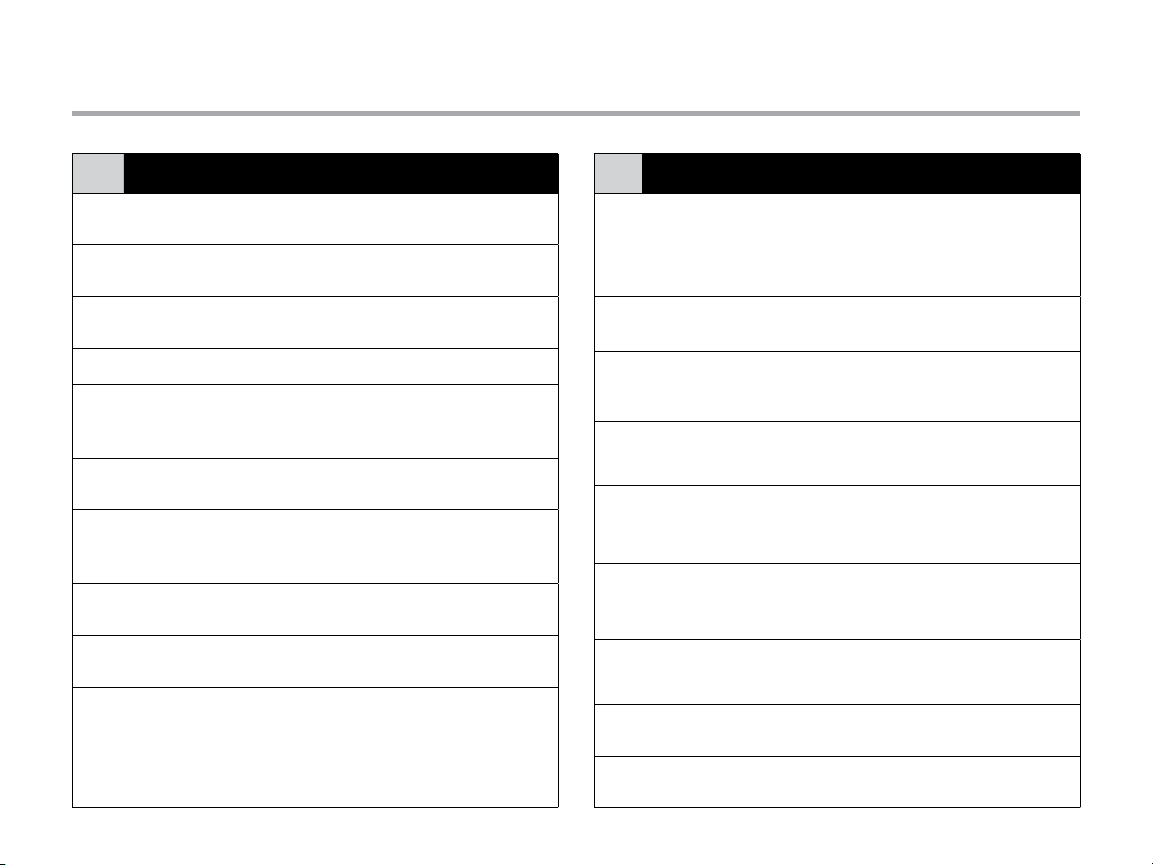
Pro-C Components (continued)
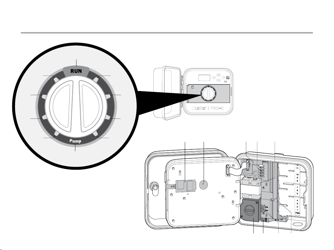
Control Dial
C
Run
①
Set Current Date/
②
Time
Set Program
③
Start Times
Set Station Run Times Set each station run time
④
Set Days to Water
⑤
Set Pump Operation
⑥
Seasonal Adjustment
⑦
Solar Sync
⑧
Manual—Single
⑨
Station
System O
⑩
®
Normal dial position for
automatic operation
Set current date and time
Set 1 to 4 start times in each
program
Select individual days to water,
odd, even or interval watering
schedule
Turn pump or master valve
on or o for each station
Make global run time changes
without programming the
controller (from 5% to 300%)
Allows user to program settings
when using Solar Sync ET sensor
Activates a one time watering of
a single station
Used to discontinue all programs
and stop all watering until the dial
is returned to the RUN position,
or to set the programmable rain
o feature
Wiring Compartment
D
9-Volt Battery
①
Reset Button
②
Power Area
③
SmartPort®
④
Input Terminals
Transformer
⑤
Junction Box
⑥
Ground Lug
⑦
Sensor Terminals
⑧
Power Slide
⑨
An alkaline battery (not included) allows
programming of the controller without
AC power
This button will reset the controller.
All programmed data will remain intact
Used to attach transformer, sensor wires,
and other systems to the controller
Used to connect a SmartPort, which
enables Hunter remote controls
A transformer is installed (Outdoor
models only, indoor models are supplied
with a plug-in transformer)
This box provides an area for connecting
primary AC power (Outdoor models only)
For additional surge protection, connect
lug to earth ground
Used to connect Hunter Solar Sync or
“Clik-type” sensors
Release to remove or insert Pro-C
modules
7
Page 8
Mounting the Controller to a Wall
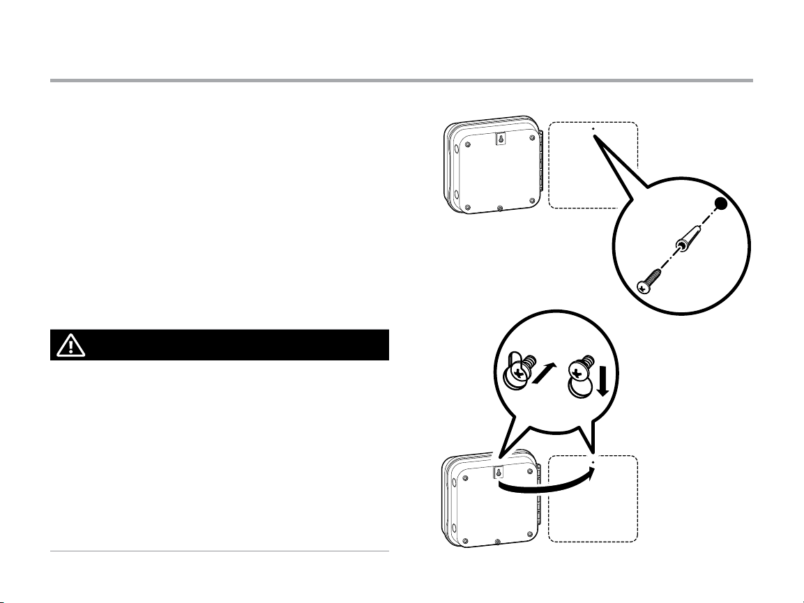
All necessa ry hardware is in cluded for most inst allations.
1. Use the hol e at the top of the controlle r as a reference and
secure a 1" (2 5 mm) screw into th e wall. Note: Install scr ew
anchor s if attaching to dr ywall or masonr y wall.
2. Align con troller with the screw a nd slide the keyhole
on top of the con troller over the screw.
3. Secu re controller in place by ins talling screws in the ho les.
For PC-401-A: If the supply cord is damaged, it must be
replaced by the manufacturer or service agent or a similarly
qualified person in order to avoid hazard.
NOTE
The indoor Pro-C is not weather or water resistant, and
must be installed indoors or in a protected area. This device
is not intended for use by young children. Never let children
play with this device.
Outdoor model is water and weather resistant. Connecting
the outdoor Pro-C to the primary power should be done
by a licensed electrician following all local codes. Improper
installation could result in shock or fire hazard. This device
is not intended for use by young children. Never let children
play with this device.
8
Page 9
Connecting AC Power
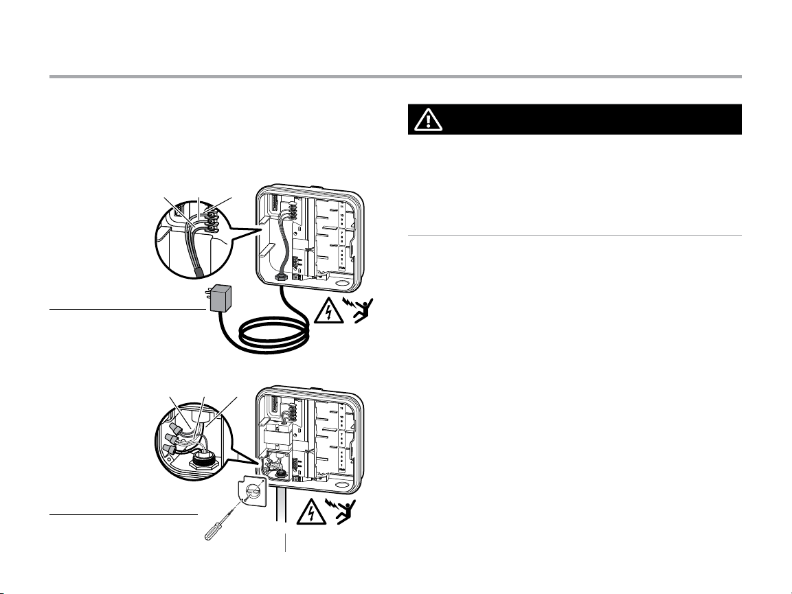
Indoor Cabinet
Route trans former cable thro ugh the hole on the bo ttom left
side of the con troller and connec t one Yellow Wire to each of the
screws marke d AC an d the Green Wire to GND.
GND
(Gree n)
AC1
(Yello w)
AC2
(Yello w)
Indoor Cabinet
GROUND
(Gree n)
NEUTRAL
(W hite)
HOT
(Black)
Outdoor Cabinet
120 V 230 V
U.S.A. INTERNATIONAL
NOTE
To be performed by a licensed electrician only.
Always use UL listed ½" (13 mm) conduit with male adapter
when installing AC wiring. Pro-C/PCC controllers are intended
to be supplied AC power with a 15A rated overcurrent
protected device.
Outdoor Cabinet
1. Route AC p ower cable and condu it through the ½" (13 mm)
conduit op ening on the lef t side of the bottom of th e cabinet.
2. Co nnect the wires to th e transformer wi res located inside the
junction box. International units are supplied with a built in
terminal s trip. Always use a UL listed co nduit ½" (13 mm) male
adapter wh en installing the AC wiring.
3. Insert t he adapter into the ½" (13 mm) hole at t he bottom of the
controller. Attach a n ut to the adapter inside th e enclosure.
4. Conn ect a 9-volt alkaline batter y (n ot included) to the ba ttery
terminals an d place in the batter y compartme nt in the front
panel. Th e battery allows t he user to program the co ntroller
without AC p ower. Wate ring will not occur wit hout AC power.
Since this contr oller has non-volatile m emory, the program
clock and c alendar will be retai ned during a power ou tage even
if no bat tery is installed.
9
Page 10
Installing Station Modules
The Pro- C controller is supplie d with a factory-i nstalled base
module fo r up to 4 stations. Additi onal modules may be a dded
in incremen ts of 3 stations (PC M-300) or a singl e 9-station
(PCM-90 0) to expand the controll er’s station capabil ity to 16
stations. Additional modules are sold separately.
The Pro- C utilizes automatic mo dule recognition fi rmware to
identif y when PCM modul es are installed or rem oved from the
controller. This feat ure will recognize the cor rect number of
station s without having to rese t or cycle power to the cont roller.
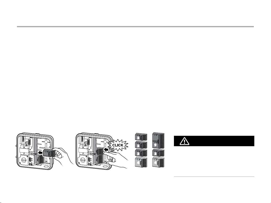
Installing PCM Modules
The Pro- C controller is designe d with a simple to use “Power
Lock” featur e that assures that the mo dules are energized a nd
firmly s ecured into the control ler. T he “Power Lock” can unlo ck
or lock all m odules at one time by simp ly pushing the “Power
Lock” s lide .
1. Slide the “ Power Lock” into the “Power Of f” (unlocked)
position. I nsert the PCM mo dules into the approp riate
sequen tial position in the contr oller cabinet.
2. Once all of t he modules are in place, sl ide the “Power Lock”
into the “Power On ” (locked) position to en ergize and secure
the modul es into the controller.
3. The P ro-C will automatica lly recognize the corre ct number of
station s. It is not necessar y to press the reset but ton or cycle
power to the con troller.
3
3
3
4
9
3
4
The use of a PC M-900 to expand you r
controller to 1 6 stations requires t hat one
PCM-300 be in stalled in the firs t expansion
slot (st ati ons 5 –7) and the PCM-900 i n the
upper t wo expansion slots.
NOTE
10
Page 11
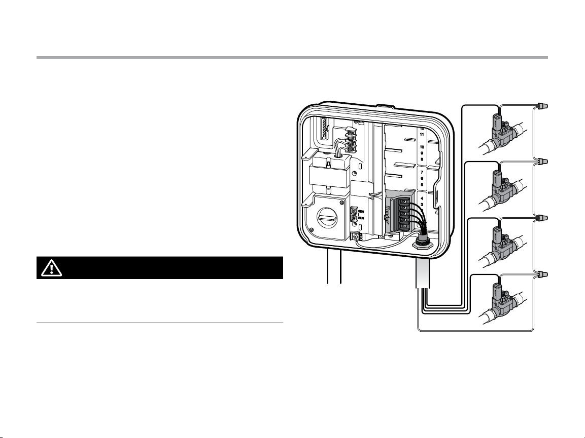
Connecting Station Wires
1. Route valve wi res between contro l valve location
and controller.
2. At valves, at tach a common wire to eit her solenoid wire
of all valves. T his is most commonly a wh ite colored wire.
Attach a sep arate control wire to th e remaining wire
of each valve. All w ire splice connecti ons should be
done using wa terproof connec tors.
3. Route va lve wires through the con duit and attach co nduit
to one of the op enings on the bot tom of the cabinet.
4. Strip ½" (13 mm) of insulation f rom ends of all wires.
Secure th e valve common wire to “COM” (Common) terminal.
Attach all in dividual valve contro l wires to the appropr iate
station terminals.
NOTE
Common terminal screw has moved from base module
and is now below the sensor terminals. Do not connect the
incoming common wires to the PM/V terminal.
4
3
2
1
COM
11
Page 12
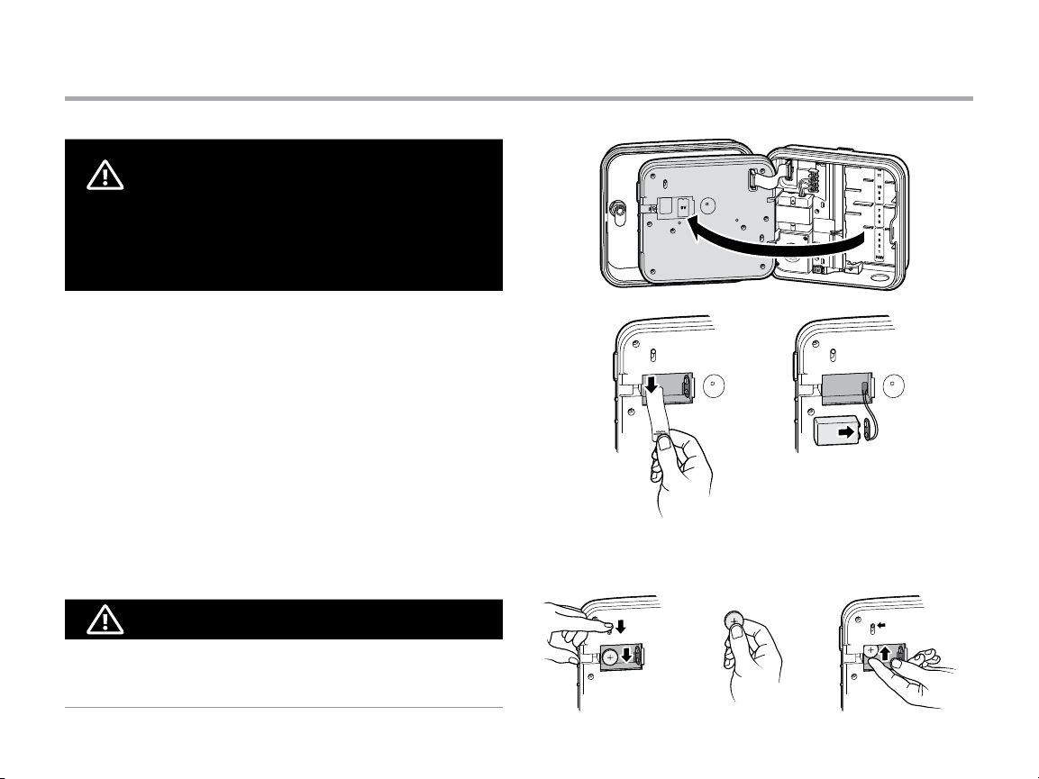
Connecting the Battery (optional)
WARNING: RISK OF FIRE, EXPLOSION, AND
ELECTRIC SHOCK. REPLACE BATTERY WITH CR2035
TYPE ONLY. Use of a dierent battery has potential for
a risk of re, explosion, and electric shock. See owner’s
manual for instructions.
Connec t a 9-volt alkaline battery (not inclu ded) to the batter y
terminals an d place in the batter y compartme nt in the front
panel. Th e battery allows t he user to program the co ntroller
without AC p ower. Wate ring will not occur with out AC power.
Since this contr oller has non-volatile m emory, the program cl ock
and calen dar will be retained d uring a power outage eve n if no
batter y is installed.
Activating the V Lithium Battery
After ins talling your Pro-C, m ake sure to remove the batte ry
contac t insulator to allow the Pro -C to keep time in the event
of a power out age.
Replacing the V Lithium Battery
NOTE
When inst alling 3V Lithium bat tery, ensure the positive (+) side
is facing up.
12
Page 13

Connecting a Master Valve (optional)
Connec t either wire from Mas ter Valve to the P/M V terminal.
Connec t remaining wire to the “COM” (Common) terminal.
4
3
2
1
P/M V
Master Valve
COM
13
Page 14

Connecting a Pump Start Relay (optional)
1. Route a wire pair f rom the pump relay into the
controller housing.
2. Conn ect the pump commo n wire to the terminal
slot “COM” (Common) and th e remaining wire
from the p ump relay to the P/M V terminal slot.
Relay holding current draw must not exceed 0.28 amps
(24 VAC). Do not connect the controller directly to the pump—
damage to controller will result.
15 (4.5 m) minimum
To p ump
PSR
14
P/M V
COM
Page 15

Connecting a Hunter “Clik” Weather Sensor (not included)
A Hunter weather sensor or other micro-switch type weather
sensors can be connected to the Pro-C. The purpose of this
sensor is to stop automatic watering when weather conditions
dictate.
1. Remove the metal jumper plate that is attached across
the two SEN terminals inside the controller.
2. Connect one wire to one SEN
terminal, and the other wire
to the other SEN terminal.
When the weather sensor
has deactivated automatic
watering, “OFF” will appear
on the display.
15
Page 16

Connecting a Hunter “Clik” Weather Sensor (continued)
Testing the Weather Sensor
The Pro-C provides simplified testing of a rain sensor when
the sensor is wired into the sensor circuit. You can manually
test proper operation of the rain sensor by using the One
Touch Manual Start (see page 26). During the Manual cycle,
pressing the test button on the “Clik-type” sensor
(eg. Mini-Clik®) will interrupt watering.
NOTE
The Manua l single station fu nction ignores a ny attached sens or
and will allo w watering to occur.
Manually Bypassing the Weather Sensor
If the rain sensor is interrupting irrigation,
you can bypass it by using the bypass switch
on the front of the controller.
Slide the switch to the Bypass position
to disable the rain sensor from the system to
allow for controller operation. You can also bypass the weather
sensor for manual operation by using the Manual function.
The Bypass switch does not affect the Seasonal Adjust update
when using the Solar Sync sensor.
16
Page 17

Connecting a Hunter Remote (not included)
The Pro-C is compatible with Hunter remote controls.
The SmartPort wiring harness (included with all Hunter
remotes) allows for fast and easy use of Hunter controls.
Hunter remotes make it possible for you to operate the system
without having to walk back and forth to the controller.
To Install the SmartPort Connector
1. Install a ½" (13 mm) female threaded “Tee” in the field
wiring conduit approximately 12" (30 cm) below the Pro-C.
2. Feed the red, white, and blue wires of the harness
through the base of the “Tee” and into the wiring
compartment as shown.
3. Screw the SmartPort harness housing into the “Tee”
as shown.
NOTE
P/N 258200 can b e used as an alternate met hod
to mount th e SmartPort con nector.
4. Attach the red wire to the screw slot marked AC1, at tach
the white wire to the screw slot marked AC2, attach the
blue wire to the screw slot marked REM.
NOTE
Reversing the re d and white wires will resu lt in an
“SP ERR ” message.
17
Page 18

Connecting a Hunter Remote (continued)
12” / 30cm
REM
(Blue)
AC2
(White)
AC1
(Red)
NOTE
Any exten sion of the wiring on the Sm artPort® may result in an
error mes sage in the controller dis play and possible mal function
of the remote un it due to radio inter ference. In some situat ions,
lengt hening of the harness m ay work fine, in others i t may not
work at all (i t is site specific). In either cas e, extending the wiri ng
harness s hould be done using shi elded cable to minimi ze the
possible effects of electrical noise. For easiest installation,
order the H unter SmartPor t shielded cable wi ring harness
(P/N ROAM-SCWH) with a full 25 f eet (7.6 m eters) of
shielded cable.
18
Page 19

Connecting to the Hunter Solar Sync
®
The Solar Sync is a sensor system that, when connected
to Hunter Pro-C, will automatically adjust your controller
watering based upon changes in local climate conditions.
The Solar Sync utilizes a solar and temperature sensor
to measure on-site weather conditions used to determine
evapotranspiration (ET), or the rate at which plants and turf
use water. In addition, the Solar Sync sensor includes
a Hunter Rain-Clik and Freeze-Clik sensor that will shut down
your irrigation system when it rains and/or during freezing
conditions.
The controller will automatically increase or decrease watering
run times based on changes in weather. The result is a new
water-efficient irrigation product that promotes water
conservation and healthier plants. You simply program your
controller like you normally would, and the Solar Sync takes
over from there, eliminating the need to manually adjust your
watering schedule.
For installation and programming instructions of your Hunter
Solar Sync, please refer to the Solar Sync owner’s manual.
19
Page 20

Setting the Current Date and Time
1. Turn the dial to the DAT E/TIME p osition.
2. The cur rent year will be flashin g in the display. Use the
j a nd k butto ns to change the year. Push the i button
to proceed to s etting the month.
3. The m onth will be flashing. Us e the j and k buttons
to change the m onth. Press the i button to proceed
to settin g the day.
4. T he day will be flashing. Us e the j and k buttons
to change the d ay of the month. Press the i button
to proceed to s etting the time.
5. The t ime will be displayed: Use the j an d k but tons
to selec t AM, PM, or 24 hr. Press the i bu tton to move
to hours. Use t he j and k buttons to change th e hour
shown on th e display. Press the i but ton to move onto
the minute s. Use the j and k buttons to chang e the
minutes sh own in the display.
The date an d time have now been set.
20
Page 21

Setting Program Start Times
1. Turn the dial to the START TIMES position.
2. Press the n butto n to select A, B, or C.
3. Use the j and k bu ttons to change the st art time.
(Advances in 15-minute increments.) One star t time will
activate all stations sequentially in that program. This
eliminates th e need to enter a star t time for each stat ion.
4. Press the i bu tton to add an additi onal start time,
or n button for the next program.
Eliminating a Program Start Time
With the dial s et to the START TIMES position, pus h the j
and k but tons until you reach 12:0 0 (Midnight). From this
position p ush the k but ton once to reach the “OFF” posi tion.
NOTE
All stati ons operate in numer ical order. Only one program start
time is required to activate a watering program.
If a progra m has all four star t times turned of f, then that
program is o ff (all other program det ails are retained).
Because t here are no start t imes, there will be no wa tering
with that program.
21
Page 22

Setting Station Run Times
1. Turn the dial to the RUN TIMES position.
2. The disp lay will show the last pro gram selected (A, B, or C)
the stati on number selec ted, and the run time fo r that
station w ill be flashing. You can switch to an other program by
pressing th e n butto n.
3. Use the j an d k b uttons to change the s tation run time
on the display. You may set sta tion run times from 1 min ute to
6 hours.
4. Press the i but ton to advance to the nex t station.
5. Repeat s teps 2 and 3 for each stati on.
22
Page 23

Setting a Watering Schedule
1. Turn the dial to the WATER DAYS position.
2. The disp lay will show the last pro gram selected (A, B,
or C). You can switch to an other program by pres sing the
n button.
3. The co ntroller displays curre ntly programme d active day
schedul e information. You can choos e to water on specific
days of the week , or you can choose inter val watering, or
choose to wa ter on odd days or even days. Ea ch program can
operate us ing only one type of w ater day option.
Selecting Specic Days
of the Week to Water
1. Press the j bu tton to activate
a parti cular day of the week
to water (the displ ay always
star ts with Monday). Press the
k b utton to cancel water ing
for that day. After p ressing a
button t he display automatically adva nces to the next day.
A V icon indica tes a water day.
A W icon indica tes a no water day.
2. Afte r programming, se t dial
to the RUN position to enable
automatic execution of all
selected programs and start
times.
Selecting Odd or Even Days to Water
This feature u ses numbered day(s) of the month for w atering
instead of sp ecific days of the week (odd days: 1s t, 3rd, 5th, etc.;
even days: 2nd, 4th, 6th, e tc.)
1. With the V cursor on SUN press the i but ton once. ODD will
flash on the s creen.
2. If even day wate ring is desired, press th e k button o nce.
EVEN will flash on the scr een. You can move ba ck and forth
from ODD to EVEN by pressing the k button.
3. O nce odd or even day watering is c hosen, turn the dial ba ck
to the RUN TIME S position to set waterin g days.
23
Page 24

Setting a Watering Schedule (continued)
Selecting Interval Watering
This feature is co nvenient if you want to have a m ore consistent
watering s chedule without h aving to worry abo ut the day of the
week or the da te. The interval you s elect is the amoun t of days
betwee n watering including t he watering day.
1. Turn the dial to the WATER DAYS position. The water drop
above Mond ay should be flashing.
2. Press the i button u ntil EVEN is flashing, the n press the i
button o ne more time. The displ ay will change to the inter val
mode and t he Interval Day numb er will be flashing.
3. Press the j bu tton. The display will n ow show two number s:
the inter val, and the days remaini ng in the interval.
4. The numb er of days between wa terings, or the inter val, will
be flashin g. Use the j and k buttons to selec t the number
of days desired b etween watering s.
5. Pres s the i butto n. The days remaining in th e interval are
now flashin g. Use the j and k but tons to select the n umber
of days until th e next desired water ing. One day remaining
means it will w ater the next day.
NOTE
If any days are se lected as non-water d ays
the display, the Inter val Day watering will e xclude tho se days.
For exampl e, if the Interval Days ar e set at 5 and Monday is a
non-water d ay, th e controller will water ever y 5th day, but never
on a Monday. If the in terval water day falls o n a Monday and
Monday is a no n-water day, the program woul d not water for
5 more days resu lting in no irrigatio n for 10 days total.
at the bot tom of
W
24
Page 25

Options for Running Your Irrigation System
Run
After pro gramming is complete, t urn the dial to the RUN
position to en able automatic execu tion of all selected
program s and start time s.
System O
Valves currentl y watering will be shut o ff after the dia l
is turned to th e SYSTEM OFF position for two se conds.
All active p rograms are disconti nued and watering
is stoppe d. To retu rn controller to norm al automatic
operati on, simply return dial to th e RUN position.
Manually Run a Single Station
1. Turn the dial to the MANUAL position.
2. Station r un time will flash in the disp lay. Us e the i
button to m ove to the desired statio n. Yo u may then
use the j and k butto ns to select the amo unt of
time for a st ation to water.
3. Turn the dia l to the RUN position to r un
the stati on (o nly the designated s tation
will water, then contro ller will return to
automatic m ode with no change in t he
previously set program).
NOTE
The Manua l single station fu nction ignores a ny attached sens or
and will allo w watering to occur.
Seasonal Adjustment
Seasonal A djust is used to make
global r un time changes witho ut reprogram ming the entire contro ller.
This feature is p erfect for m aking
small chang es that are necessar y as
the weather c hanges. For instan ce, hotter times of the
year may requir e a bit more water. Seasonal adjus t can
be increas ed so that the statio ns will run longer than
the programmed time. Conversely, as Fall approaches,
the seaso nal adjust can be redu ced to allow for shor t
watering durations.
1. Turn the dial to the SEA SONAL ADJUST position.
2. Pres s the j or k button s to set the percentage
desired fro m 5% to 300%.
To view the new adjuste d run time, turn the dial
to set run tim e’s p osition. The displayed r un times will
be update d accordingly as the seas onal adjustment
is made.
NOTE
The contro ller should always be i nitially programm ed
in the 100% p osition.
25
Page 26

Options for Running Your Irrigation System (continued)
One Touch Manual Start and Advance
You can also activ ate a program to water wit hout using the dial.
1. With the dia l in the RUN position, hol d down the i but ton for
2 seconds.
2. This feat ure automatically def aults to program A . You can
select program B, or C by pressin g the n program.
3. The s tation number will b e flashing. Press the h or i b utt on
to scroll thro ugh the stations an d use the j and k buttons
to adjust th e station run times. ( If no buttons are pres sed
during ste p 2 or 3, the controller will a utomatically begi n
program A.)
4. Press the i bu tton to scroll to the st ation you wish to begin
with. Afte r a 2 second pause, the pro gram will begin.
This feature is g reat for a quick cycle w hen extra wateri ng is
needed o r if you would like to scroll thro ugh the stations to i nspect
your syste m.
26
Page 27

Using the Pro-C to Operate Outdoor Lighting (optional)
Connecting the FX Transformer
The Pro- C is capable of opera ting three separate lig hting
transfo rmers equipped w ith the PXSync inter face box.
Connec t wires from the firs t PXSync box to station o utput 1
(and the Common) on the Pro -C terminal. If using a se cond or
third trans former, the second will be w ired to station 2 and th e
third wil be w ired to station 3.
NOTE
Manual c ycles initiated at the cont roller or from a remote wi ll
cancel any au tomatic program cu rrently running. On ce manual
cycle is comp lete, the controller will re turn to automatic mod e,
and run th e next schedule d program at its spe cified star t time.
Common
Station Output
Transformer
Accessory Plug
27
Page 28

Using the Pro-C to Operate Outdoor Lighting (optional)
Creating a Lighting Program
1. Turn the dial to th e START TIMES position.
2. Press an d hold the n but ton for 6 seconds an d observe the
A, B, C programs moving.
3. L1 an d a flashing “OFF” will app ear, a nd the controller is read y
to designate lighting programs.
4. Add a st art time to lighting p rogram L1 by pressing the j a nd
k b uttons until the cor rect time is shown. Up to f our start
times can b e assigned to L1.
5. Turn the dial to t he RUN TIMES position. P ress the n button
repeatedly until L1 is s hown. Use the j a nd k butto ns to add
a run time to lig hting program L1.
If using a secon d or third lighting tra nsformer, repeat the above
process ste ps after connec ting the additional PX Sync boxes and
adding st art and run time s accordingly.
You do not need to pro gram days of the week for l ighting
program s, as they run every day a ccording to the progra mmed
star t and run times.
NOTE
Once a sta rt time is assigned to p rogram L1, it turns stat ion 1
from an irr igation station to a li ghting station (same fo r L2 and
L3). As a res ult, when creating prog rams for irrigati on A, B, or C,
station 1 w ill show USED since L1 has been assig ned a start tim e.
Example of screen upon entering
Example of ashing screen while holding down on n button
Lighting program can be activated
28
Page 29

Advanced Features
Set Pump/Master Valve Operation
The defa ult is for all stations to h ave
the master v alve/pump start circ uit ON.
The maste r valve/pump start c an be set
ON or OFF by station , regardless of
which program the station is assigned.
To program pump operation:
1. Turn the dia l to the PUMP position.
2. Press the j or k butto ns to toggle the maste r valve/pump
start ON or OFF for the specific s tation.
3. Pres s the i but ton to advance to the nex t station.
4. Repeat step s 2 and 3 for all necessar y stations.
Programmable Rain O
This feature p ermits the user to s top all
program med waterings for a d esignated
period f rom 1 to 31 days. At the end of the
program mable rain off p eriod, the control ler
will resume normal automatic operation.
1. Turn the dial to the SY STEM OFF
position.
2. Pre ss the j but ton and a 1 will be
displayed an d the DAYS LEFT ic on
will illuminate.
3. Press j as many times as needed to s et the number of days
off desi red (up to 31).
4. Turn the dial bac k to the RUN position, at
which time, OFF, a number and t he DAYS ico n
all remain on.
5. Leave t he dial in the RUN position.
The days of f remaining will decre ase at
midnight o f each day. When it goes to
zero, the display w ill show the normal
time of day and n ormal irrigatio n will
resume at th e next schedule d start time.
Setting Specic Day(s) O
Program ming a No Water Day(s) is useful to inhibit water ing on
mowing days, e tc. For instance, if you a lways mow the lawn on
Saturdays yo u would designate Sat urday as a No Water Day so
you are not mow ing wet grass.
1. Turn the dia l to the WATE R DAYS position.
2. Ent er an interval water ing schedule as
describ ed on page 24.
3. Press the i but ton once. MON will be flash ing.
4. Use the i but ton until the curso r is at
the day of the we ek you wish to set as
a No Water Day.
5. Press the k but ton to set this day as
a no water day. The W will illuminate
over this day.
6. Repeat s teps 4 and 5 until all desire d event day(s) a re off.
29
Page 30

Hidden Features
Program Customization
The Pro- C is factory conf igured with 3 indep endent program s
(A, B, C with fou r start times eac h) fo r different plan t type
requireme nts. The Pro-C ca n be customized to display o nly the
required p rograms. You can hide those pr ograms that are not
required to ease programming.
1. Start with th e dial in the RUN position.
2. Press an d hold the k bu tton. Turn the dial to the WATER
DAYS position.
3. Release th e k buttons.
4. Use the j and k butto n to change program mo des.
Advanced Mode
(3 programs / 4 start times)
Limited Mode
(1 program / 1 start time)
Normal Mode
(2 programs / 4 start times)
30
Programmable Delay Between Stations
This feature a llows the user to inser t a delay between wh en
one stat ion turns off and th e next station t urns on. This is
very hel pful on systems with sl ow closing valves or on pum p
systems tha t are operating near m aximum flow or have slow
well recover y.
1. Start with th e dial in the RUN position.
2. Press an d hold the k bu tton while turnin g the dial to the
RUN TIMES position.
3. Release the k bu tton. The display
will show a dela y time for all
stations in seconds.
4. P ress the j an d k bu tton s
to increase or d ecrease the delay time b etween 0 and 59
seconds in 1 s econd increment s and then in one minute
incremen ts up to four hours. Hr will be disp layed when the
delay chang es from seconds to minu tes and hours. Maxim um
delay is 4 hour s.
5. Return th e dial to the RUN position.
NOTE
The Maste r Valve/Pum p Start ci rcuit will operate dur ing the first
15 seconds o f any programmed d elay to aid in the closing of the
valve and to avoi d unnecessary c ycling of the pump.
Page 31

Hidden Features (continued)
Programmable Sensor Override
The Pro- C allows the user to progr am the controller so tha t the
sensor disables watering on only desired stations. For example,
patio gard ens that have pots unde r overhangs and roof s may
not receive wa ter when it rains and will co ntinue to need to be
watered dur ing periods of rain. To progr am sensor override:
1. Turn the dial to the RUN position .
2. Press an d hold the k bu tton while turnin g the dial
to the START TIMES position.
3. Release the k bu tton. The display wil l show the station
number, the SENSOR icon, a nd ON will be flashing.
4. Press the j or k bu tton to enable or disa ble the sensor
for the st ation shown.
ON = Sensor enable d (w ill suspend irriga tion)
OFF = Sensor disab led (will allow wa tering)
5. Use the h or i bu ttons to scroll to the nex t station that you
would like to prog ram the sensor overr ide.
A station t hat is running in the sen sor override mode wil l display
the word “SENSOR” and flash th e
D icon.
NOTE
The contro ller default is for the s ensor to disable water ing on all
zones when rain occurs.
31
Page 32

Hidden Features (continued)
Total Run Time Calculator
The Pro- C keeps a run ning total of each progr am’s station r un
times. This f eature provides a quick w ay to determine how long
each progr am will water.
1. While in the RUN TIMES mode use th e i button to a dvance to
the highest station position.
2. Press the i butto n once to review the total of all r un times
programmed.
3. Use the n but ton to review addition al programs.
Test Program
The Pro- C allows the user a simplif ied method for ru nning a
test prog ram. This feature ope rates each station in n umerical
sequen ce, from the lowest to the hig hest. You can start wi th any
station . This is a great feature to che ck the operation of you r
irrigation sys tem.
To initiate the test pr ogram:
1. Press and h old the n but ton. The station nu mber will be
flashing.
2. Press the h or i butto n to scroll to the station yo u would like
the test pro gram to start w ith. Use the j an d k button to
set a run tim e of up to 15 minutes. The run t ime needs to be
entered onl y once.
3. After a 2 se cond pause, the test p rogram will begin.
Easy Retrieve™ Program Memory
The Pro- C is capable of saving th e preferred watering p rogram
into memor y for retrieval at a la ter time. This feature allows f or a
quick way of res etting the controll er to the original prog rammed
watering schedule.
To save the program in to memory:
1. With t he dial in the RUN positio n, press and hold the j an d n
button s for 3 seconds. The dis play will scroll S f rom left to righ t
across the dis play indicating the p rogram is being saved i nto
memory.
2. Release the j and n buttons.
To retrieve a program t hat was previously s aved into memory :
1. W ith the dial in the RUN pos ition, press and hol d the k an d
n button s for 3 seconds. The dis play will scroll S f rom right
to left a cross the display indica ting the program is b eing
retrieved from memory.
2. Release the k and n buttons.
32
Page 33

Hidden Features (continued)
Solar Sync Delay for Pro-C
The delay feature is accessible only after the installation
of the Solar Sync. The Solar Sync Delay feature allows the user
to postpone seasonal adjustment changes from being made
by Solar Sync for up to 99 days.
While the S olar Sync Delay is active, th e Solar Sync will contin ue
to collect a nd store data.
Operation:
To access the Solar Sync D elay setting:
1. Place the dial i n the RUN position; press an d hold the j
button , rotate the dial to the Sol ar Sync position then rel ease
the j butt on. The following scr een will be presente d: d:XX
(where d indicates days a nd XX indicates the numbe r of days
to be delayed) .
2. Press the j or k b utton to increase/decreas e the number
of days the delay s hould run. Once the d esired number of days
is displayed, m ove the dial back to the RUN positio n to activate
th e de lay.
NOTE
The numb er of days remaining will no t be displayed on the RUN
screen. To check if th e Delay feature is active, o pen the Solar Sync
Delay menu a nd check the days displaye d. If 1 or more days are
displayed, th en Solar Sync Delay is ac tive, if 00 is displayed then
Solar Sync D elay is not active.
To change the existi ng Delay days setting :
1. Open the S olar Sync Delay menu by p ressing the j button
and rotati ng the dial to Solar Sync Se ttings and releas e the
j button.
2. Use the j or k keys to m odify the numb er of days until
desired num bers of delay days is displaye d. (Setting the days
to 00 turns S olar Sync Delay to OFF.)
3. Ret urn the dial to the RUN posi tion for the changes to
take ef fect .
While Sola r Sync Delay is active, the S olar Sync will continue
to gather wea ther information a nd calculate the Seas onal
Adjust Value. Th e updated seasonal a djust will be applie d once
the Solar Syn c Delay days reach 00.
33
Page 34

Hidden Features (continued)
Cycle and Soak
The Cycle and Soak feature allows you to split a station’s
run time into more usable, shorter watering durations. This
feature is useful when applying water to slopes and tight soils
because it automatically applies water more slowly, helping to
prevent runoff from occurring. You should enter the Cycle time
as a fraction of the station’s watering time, and the Soak time
as the minimum number of minutes required before watering
can occur again for the next Cycle. The total number of cycles
is determined by taking the total programmed station run
time and dividing it by the Cycle time.
Accessing the Cycle and Soak Menu:
The Cycle and Soak feature is accessed by placing the dial
in the RUN position, pressing and holding the j button for
3 seconds; while holding the j button rotate the dial to the
RUN TIME dial position, then release the button.
Example of Cycle screen upon
entering
Example of Cycle screen with
only minutes
Setting the Cycle Time:
Initially Station 1 will be displayed. To access other stations,
press the h or i button.
Once the desired station is displayed, use the j or k button
to increase or decrease the Cycle time. The user can set the
time from 1 minute to 4 hours in 1 minute increments or to OFF
if no Cycle is desired.
NOTE
Before 1 hour, only minutes are displayed (e.g. 36). At 1 hour
or above, the display will change to include the hour digit (e.g.
1:13 and 4:00).
If a station’s Run Time is less than or equal to the Cycle time,
then no Cycle will be applied.
Example of Cycle screen with
hours included
34
Page 35

Hidden Features (continued)
Accessing the Soak Menu:
Once the desired Cycle times for each station have been
programmed, the Cycle time can be accessed by pressing the
n button.
The station will remain the same as was previously displayed
under the Cycle time (i.e. if station 2 is displayed in the Cycle
menu then Station 2 will be displayed upon pressing the
n b utton).
NOTE
The Soak menu cannot be accessed without a programmed
Cycle time.
Setting the Soak Time:
To access the other stations, press the h or i button.
NOTE
When changing the stations, if a station without a Cycle time
is encountered, the screen will revert back to the Cycle time.
Move to the next station with a Cycle Time and press the n
button to return.
Once the desired station is displayed, the user can use
the j or k button to increase or decrease the Soak time.
The user can set the Soak time from 1 minute to 4 hours
in 1 minute increments.
NOTE
Before 1 hour, only minutes are displayed (e.g. 36). At 1 hour
or above, the display will change to include the hour digit
(e.g. 1:13 and 4:00).
Example of Soak screen with
only minutes
Example of Soak screen with
hours included
Cycle and Soak Situations:
Station 1 requires 20 minutes of
watering, but after 5 minutes,
runoff occurs. However, after 10
minutes all the water is absorbed.
The solution would be to program
20 minutes for the station run time,
5 minutes for the Cycle time, and 10
minutes for the Soak time.
Station 10 c ycle running
35
Page 36

Hidden Features (continued)
Hunter Quick Check
This circuit d iagnostic procedu re is can quickly identi fy “shorts”
commonly c aused by faulty s olenoids or when a bar e common
wire touch es a bare station contr ol wire.
To initiate the Hunte r Quick Check test pro cedure:
1. Press the j , k , h a nd i buttons simultaneously. In the
standb y mode, the LCD will display all s egments (helpf ul
when troubleshooting display probl ems).
2.
Press the j but ton to begin the Quic k Check test procedu re.
The syste m will search all statio ns to detect a high curr ent
path throu gh the station term inals. When a field wir ing short is
detecte d, an ERR symbol prece ded by the station num ber will
moment arily flash on the cont roller LCD display. After the Hunt er
Quick Check completes running this circuit diagnostic procedure,
the control ler returns to the automa tic watering mode.
™
Clearing Controller’s Memory/Resetting Controller
If you feel tha t you have misprogramm ed the controller, there
is a process tha t will reset the memor y to factory d efaults and
erase all pr ograms and data tha t have been entered into th e
controller. Press an d hold the n bu tton. Press and rele ase
the RESET but ton on the back of the fr ont panel. Wait until the
display shows 12 :00 am. Release the n but ton. The controller
is now ready to b e reprogrammed.
NOTE
Any programs that have been saved with Easy Retrieve will
remain after resetting controller.
WINTERIZING YOUR SYSTEM
In regions w here the frost level fal ls below the depth of the
installe d piping, it is common fo r systems to be “winter ized”.
Several me thods can be used to dr ain the water from the sy stem.
If compress ed air method is used, i t is recommended that a
qualifie d licensed contrac tor perform this t ype of winteriza tion.
WARNING! WEAR ANSI APPROVED SAFETY EYE
PROTECTION! Extreme care must always be taken when
blowing out the system with compressed air. Compressed
air can cause serious injury, including serious eye injury
from ying debris. Always wear ANSI approved safety eye
protection and do not stand over any irrigation components
(pipes, sprinklers, and valves) during blow out. SERIOUS
PERSONAL INJURY MAY RESULT IF YOU DO NOT
PROCEED AS RECOMMENDED.
36
Page 37

Troubleshooting Guide
Problem Cause Solution
The controller repeats itself or
continuously waters, even when it
should not be on (cycling repeatedly).
There is no display. Check AC power wiring. Correct any errors.
The display reads “SP ERR”. Electrical noise is entering the system.
The display reads “P ERR”. There is a fault in the pump start,
The display reads a station number and
ERR, such as “2 ERR”.
The display reads “NO AC”. There is no AC power present
Too many start times (user error). Only one start time per active program
is required. Refer to “Setting Program
Start Times” on page 21.
Check the SmartPort® wiring harness.
Verify that the red wire is attached to the
AC1 terminal, the white wire to the AC2
terminal and the blue wire to the REM
terminal. If the wires were extended then
they will need to be replaced with shielded
cable. Contact your local distributor for
information on shielded cable.
Check the master valve or pump start
master valve, or the wiring for the
pump start/master valve.
There is a fault in the station solenoid,
or the station wiring.
(the controller is not receiving power).
wire for continuity. Replace or repair
the shorted wire. Check that all wire
connections are good and watertight.
Check the station wire for continuity.
Replace or repair shorted wire. Check
that all wire connections are good
and watertight.
Check to see if the transformer is
properly installed.
37
Page 38

Troubleshooting Guide (continued)
Problem Cause Solution
The display reads “SENSOR OFF”. The rain sensor is interrupting irrigation
or the sensor jumper is not installed.
Rain sensor will not shut off system. Incompatible rain sensor or the jumper
was not removed when sensor was
installed.
Manual Single Station Mode Used.
The controller does not have a start time
for each station.
Valve will not turn on. Short in wiring connections.
Programming error, dial in incorrect
position.
Bad solenoid.
Slide the Rain Sensor switch on front
panel to the BYPASS position to bypass
rain sensor circuit, or install the sensor
ju mpe r.
Make sure sensor is micro-switch type
such as Mini-Clik®. Check that the
jumper has been removed from the SEN
terminals. Confirm proper operation
(see “Testing the Weather Sensor” on
page 16).
Manual Single Station Mode will override
the sensor. Use Manual All Station Mode
to test sensor.
Be sure the dial is in correct position.
Total number of stations can be easily
checked by placing dial in the RUN TIMES
position and pressing the back arrow.
Check field wiring.
Replace solenoid.
38
Page 39

Certicate of Conformity to European Directives
Hunter Industries declares that the irrigation controller Model Pro-C complies with the standards of the European Directives
of “electromagnetic compatibility” 87/336/EEC and “low voltage” 73/23/EEC.
Senior Regulatory Compliance Engineer
FCC Notice
This controller generates radio frequency energy and may
cause interference to radio and television reception. It has
been type tested and found to comply with the limits for a
Class B computing device in accordance with the specifications
in Subpart J of Part 15 of FCC Rules, which are designed to
provide reasonable protection against such interference
in a residential installation. However, there is no guarantee
that interference will not occur in a particular installation.
If this equipment does cause interference to radio or television
reception, which can be determined by turning the equipment
off and on, the user is encouraged to try to correct the
interference by one or more of the following measures:
• Reorient th e receiving antenna
• Move the contro ller away from the receive r
• Plug the co ntroller into a diff erent outlet so that co ntroller
and receiver a re on different br anch circuits
If necessa ry, the user should consul t the dealer or an exper ienced
radio/television technician for additional suggestions. The user
may find th e following bookle t prepared by the Feder al
Communic ations Commission hel pful: “How to Identif y and
Resolve Radio -TV I nterference Prob lems.” This booklet is
available f rom the U.S. Governmen t Printing Off ice, Washington,
D.C., Stock No. 004-0 00-00345 -4 (price: $2.00)
This product should not be used for anything other than
what is described in this document. This product should only
be serviced by trained and authorized personnel.
39
Page 40

HUNTER INDUSTRIES INCORPORATED | Built on Innovation
1940 Diamond Street, San Marcos, California 92078 USA
www.hunterindustries.com
®
LIT-605_ENG 1/14
 Loading...