

NODE
ES
Programador de pilas
Manual del usuario e instrucciones de programación
EN
Battery-Operated Controller
Owner’s manual and programming instructions
FR
Programmateur à piles
Manuel de l'utilisateur et consignes de programmation
IT
Programmatore a batteria
Manuale dell’utente e istruzioni per la programmazione
DE
Batteriebetriebenes Steuergerät
Bedienungs- und Programmieranleitung
PT
Controlador de Funcionamento a Pilhas
Manual do Proprietário e Instruções de Utilização
TR
Pilli Kontrol Ünitesi
Kurulum, Programlama ve Kullanım Kılavuzu

EN
TABLE OF CONTENTS
NODE FEATURES ............................................... 2
NODE COMPONENTS ...........................................3
Control Buttons
LCD Display
CONNECTING THE BATTERY/BATTERIES
......................... 4
ATTACHING SOLENOIDS ........................................ 5
To Wire DC Solenoids to the NODE
To Mount the NODE to a Valve (Figure 1)
MOUNTING THE NODE
..........................................6
CONNECTING A WEATHER SENSOR ..............................6
Setting the Date and Time
IDLE MODE .................................................... 7
RUN MODE ..................................................... 7
PROGRAMMING. . . . . . . . . . . . . . . . . . . . . . . . . . . . . . . . . . . . . . . . . . . . . . . . 7
Setting Watering Start Times
Setting the Run Times
Setting Watering Days
Selecting Odd/Even Days to Water
Selecting Interval Days to Water
Setting the Seasonal Adjustment
Turning the System O
Manual Watering
Sensor Operation
ADVANCED PROGRAMMING FEATURES
..........................12
Sensor Bypass
Easy Retrieve Memory
Setting Master Valve Operation (NODE-200, NODE-400,
& NODE-600 Only)
Programmable O (Up to 99 Days)
BATTERYLIFE INDICATOR
..................................... 14
RESETTING CONTROLLER ...................................... 14
TROUBLESHOOTING GUIDE .....................................15
SPECIFICATIONS .............................................. 16
NOTES .........................................................17
1

EN
NODE FEATURES
• Simple push-button programming
• Single-station model (NODE-100) with DC latching solenoid. Single-, two-, four-, or six-station models are also available
(solenoids not included).
• Large Liquid Crystal Display (LCD) with easy-to-understand icons
• Operates using at least one standard nine-volt alkaline battery (use two for extended battery life)
• Three programs (A, B, or C) with up to four start times each
• Run times from one minute to six hours
• Manual watering capabilities
• Battery-life indicator
• Wired rain sensor compatible
• Non-volatile memory retains all program information
• Seasonal Adjustment from 10–150%
• Easy Retrieve™ memory allows saving/retrieval of preferred program data
• Manual bypass of rain sensor
• Total Run Time Calculator shows total program irrigation time per program
2

EN
NODE COMPONENTS
This section provides an overview of some of the components of the
NODE. Each item will be discussed in further detail later. However, this
section can be helpful in getting acquainted with the dierent options
available.
Control Buttons
1.
Button
– Increases the selected ashing display
2.
Button
– Decreases the selected ashing display
3.
Button
– Selects programming function
4.
Button
– Advances the selected ashing display back to the
next item
5.
Button
– Navigates the selected ashing display back to the
previous item
6.
Button
– Selects the program (A, B, or C)
LCD Display
1.
Main Display
– Indicates all program information
2.
Station Number
– Indicates the station number being programmed
3.
Start Time Number
– Indicates the start timer number being
programmed
4.
Program
– Indicates the program (A, B, or C)
5.
Current Time/Day
– Indicates when current day/time is
being set
6.
Start Times
– Indicates when start times are being set
7.
Run Times
– Indicates when Run Times are being set. Allows
user to set run times from one minute to six hours.
8.
Watering Days
– Allows the user to select individual days to
water or a selected number of days between watering (interval)
9.
% Seasonal Adjustment
– Allows the seasonal adjustment to be
programmed form 10–150% (default value is 100%)
10.
System O
– Indicates that watering is suspended
11.
Manual On/O
– Indicates when manual watering is
programmed. Allows the user to activate the station manually.
12.
MV
– Indicates that station one is set to master valve operation
(only available on two-, four-, or six-station models)
13.
Battery Status
– Indicates remaining battery life
14.
Umbrella
– Indicates the rain sensor is suspending irrigation
15.
Crossed Umbrella
– Indicates the rain sensor has been
manually bypassed
3

EN
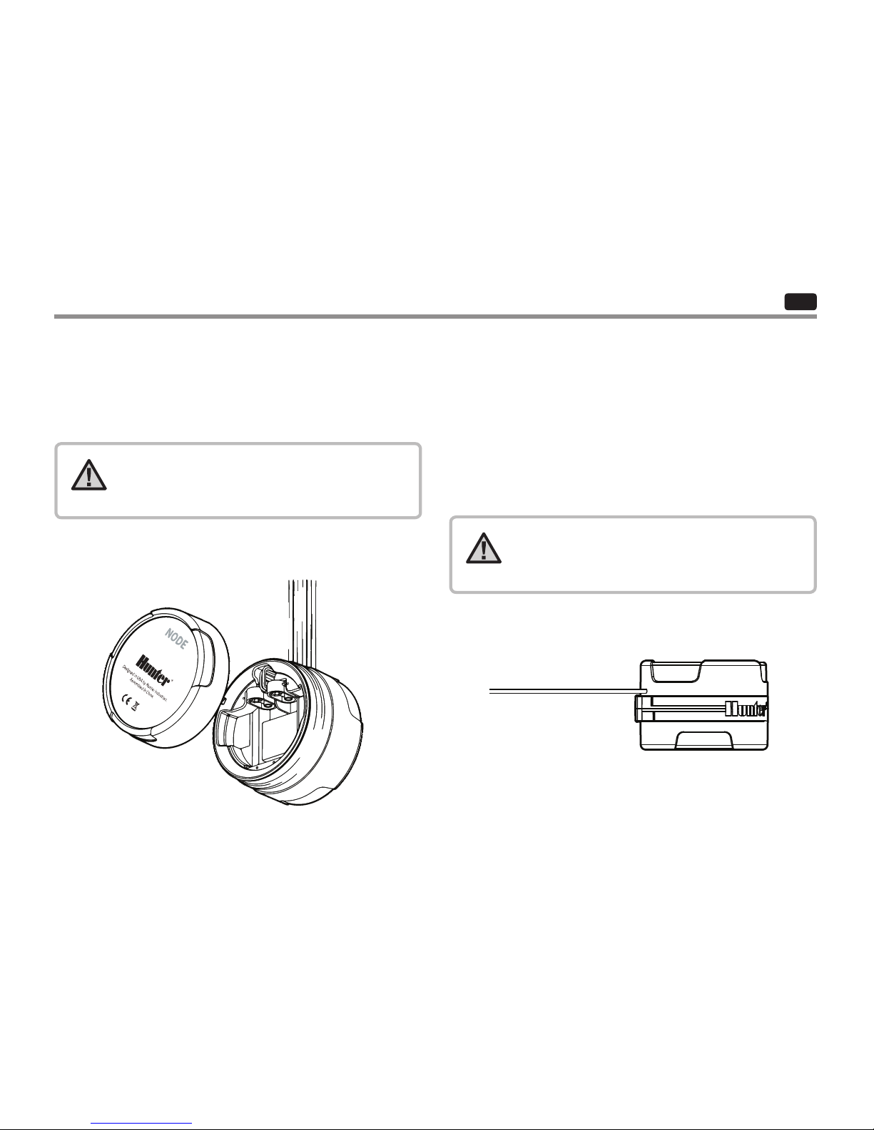
To Install the Battery/Batteries
1. Unscrew the rear body of the NODE body to gain access to the
battery compartment.
2. Insert the battery/batteries into the battery tray and connect to
the controller using the battery connector.
3. Make sure that no water is inside the battery compartment.
4. Screw the NODE rear body back onto the front half.
NOTE: Verify that the seal marker on the rear half
of the NODE lines up with the front half, ensuring
that a proper seal is created.
The NODE uses one or two standard nine-volt batteries (not included)
to operate the valves and program the controller. The controller can
operate using either a single nine-volt battery or using two nine-volt
batteries. Under normal conditions, the expected life is one year for a
single battery and two years when using two nine-volt batteries.
NOTE: The NODE has non-volatile memory. This
allows the battery to be removed without losing
program information.
CONNECTING THE BATTERY/BATTERIES
4

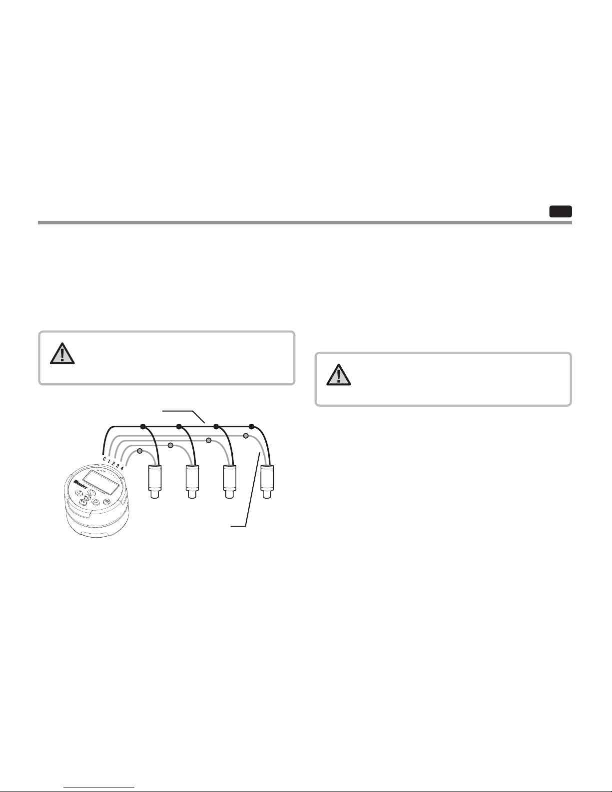
Common Wire (Black Leads)
EN
ATTACHING SOLENOIDS
The NODE-100 is provided with a solenoid attached to the controller.
The NODE-100-LS does not include a solenoid. The NODE-200,
NODE-400, and NODE-600 multi-station controllers will operate up to
two, four, or six solenoids, respectively. Hunter DC-latching solenoids
(P/N 458200) can easily be installed on all Hunter plastic valves.
NOTE: Use DC latching solenoids operating
between 9-11 VDC. 24 VAC solenoids will not
operate with the NODE.
To Wire DC Solenoids to the NODE
1. Attach the black leads from each solenoid to the single common
wire (black lead) coming from the NODE. Secure all wire
connections with waterproof connectors.
2. Attach one red wire from each solenoid to the corresponding
station wire (red lead) from the NODE. The station numbers are
identied on the face of the NODE. Secure all wire connections
with waterproof connectors.
NOTE: The maximum wire distance between the
solenoid and NODE is 100' (30 m) using 18 AWG
(1 mm) minimum wire size.
Station Wire (Red Leads)
5

Figure 1 Hunter Model Mini-Clik
®
EN
The NODE can easily be mounted on any Hunter plastic valve. A
specially designed valve mounting clip makes installation a snap. A
protective rubber cover is provided to prevent dirt from accumulating
on the face of the NODE.
To Mount the NODE to a Valve (Figure 1)
. Screw the Hunter DC latching solenoid (P/N ) into
the valve bonnet.
. Set the small open end of the NODE holder on top of the solenoid.
. Set the NODE controller into the large open end of the
NODE holder.
A Hunter Mini-Clik
®
or Wired Rain-Clik® rain sensor can be connected
to the NODE. The purpose of this sensor is to stop watering when
weather conditions dictate.
1. Cut the yellow wire loop attached to the NODE at approximately
the middle of the loop.
2. Remove approximately ½" (13 mm) of insulation from each wire.
Attach one yellow wire to each of the wires of the weather sensor.
You can mount the rain sensor up to 100 (30 m) from the NODE
controller (18 AWG/1 mm minimum wire size).
3. Secure wire connections with waterproof connectors.
CONNECTING A WEATHER SENSOR
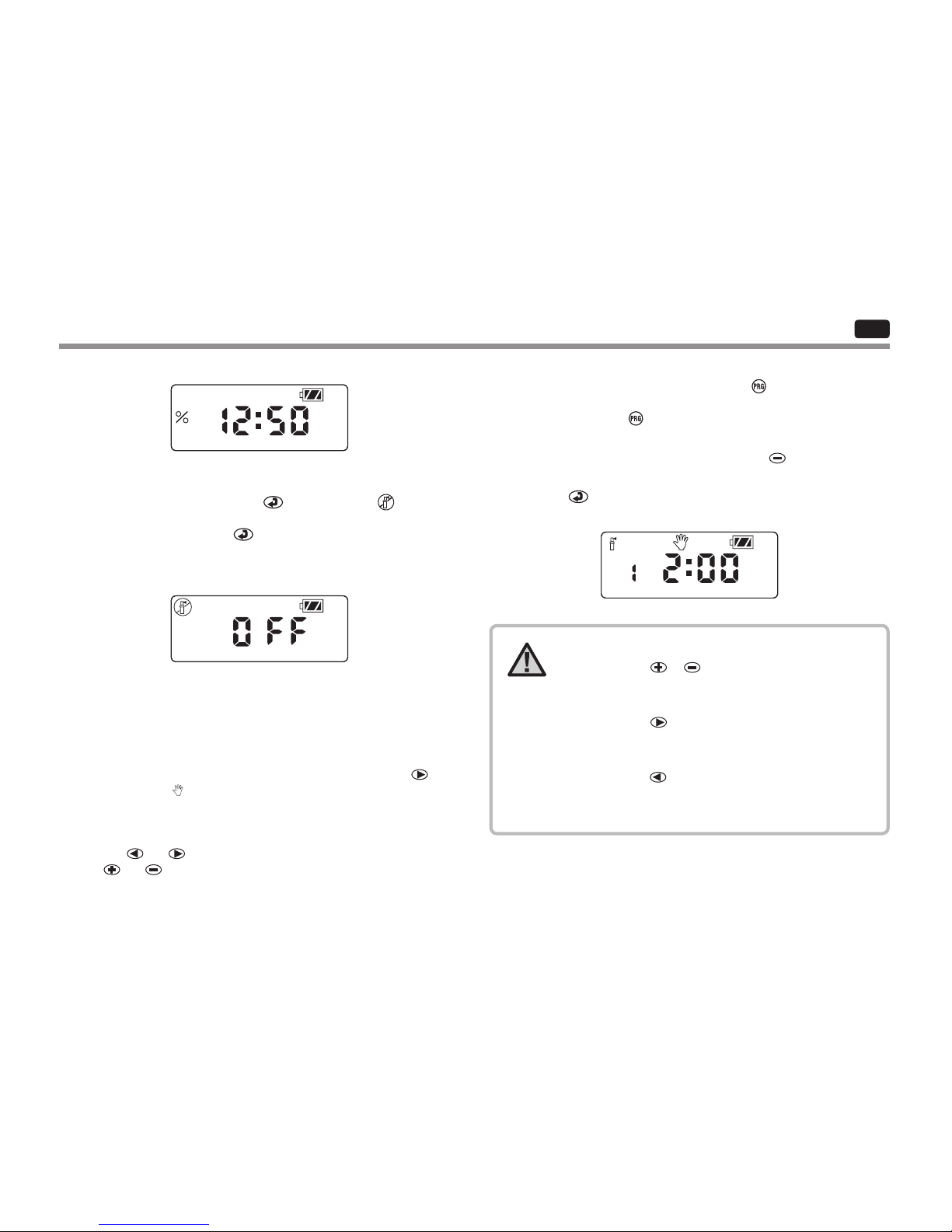
NOTE: When the Wired Rain Sensor is interrupting
the watering, the display will show the System O
icon , “OFF” and on the display.
MOUNTING THE NODE
NODE holder
6

EN
IDLE MODE
RUN MODE
Normally, the NODE display shows the time and day, day of the
week, MV (if master valve option is activated), and the battery-life
indicator. Aer a short period of inactivity, the display will shut o to
retain battery power. Pressing any button will bring the NODE into
idle mode.
When the controller is operating a program, the items shown on the
display will include the station number, program letter, remaining
run time, and the blinking Rotor icon.
The NODE uses standard Hunter controller programming with three
programs (A, B, or C) and four start times per program. On standard
Hunter controllers a dial is used to scroll between the programming
functions. However, on the NODE the
button is used to quickly
and easily create the irrigation program. When programming, the
ashing portion of the display can be changed by pressing the
or
buttons. To change something that is not ashing, press the
or
buttons until the desired item is ashing.
Setting the Date and Time
1. Push the button until the icon is displayed.
2. All four digits will be displayed representing the year. Use the
or
buttons to change the year. Press the button to proceed
to setting the month.
3. All four digits will be displayed with the two digits on the le
representing the month ashing. Use the
or buttons to
change the month. Press the
button to proceed to setting
the day.
4. Only the two digits on the right side will be displayed and ashing,
representing the day. Press the
or buttons to change the
day. Press the
button to proceed with changing the hour. Press
the
button to proceed to setting the time.
5. The AM/PM/24-hour time setting is shown ashing. Press the
or
button to change the time setting to AM, PM, or 24-hour
time. Press the
button to proceed to setting the hour.
PROGRAMMING
7

EN
6. All four numbers are shown with the two numbers on the le
ashing, representing the hour. Use the
or buttons to
change the hour. Press the
button to proceed to setting
the minutes.
7. All four numbers are shown with the two numbers on the right
ashing, representing the minutes. Use the
or buttons to
change the minutes. Pressing the
button will advance
to the year setting at Step 2.
8. Press the
button to proceed to the next programming function
or allow controller to return to idle mode.
Setting Watering Start Times
1. Press the button until the icon is displayed.
2. The start time will be displayed ashing, along with the program
letter (A, B, or C) and the start time number (1, 2, 3, or 4) in the
upper le of the display. Up to 4 dierent start times can be set for
each program.
3. Use the
or buttons to change the start time for the program
that is displayed. Each press of the button will change the start
time in one-minute increments.
4. Press the
button to add an additional start time to the program
displayed. The start time number is shown in the upper le corner
of the display.
5. Press the
button to add start times to a dierent program.
6. Press the
button to proceed to the next programming function
or allow controller to return to idle mode.
NOTE: Aer programming the run time for the last
station press the button to display the total run
time for the program.
Setting the Run Times
1. Press the button until the icon is displayed.
2. The run time will be displayed ashing. Also shown is the program
letter (A, B, or C) and the active station number on the lower
le side of the display. Press the
or buttons to change the
station run time from one minute to six hours.
3. Press the
button to advance to the next station.
4. Press the
button to add a run time to another program.
5. Press the
button to proceed to the next programming function
or allow controller to return to idle mode.
PROGRAMMING CONTINUED
8

EN
Setting Watering Days
1. Press the button until the icon is displayed.
2. The program letter (A, B, or C) will be displayed.
3. Arrows point at the specic days of the week on which watering
will occur. Press the
or buttons to scroll though the days.
4. Press the
button to activate that day for the program displayed, or
the
button to cancel watering for that day. The arrow will show
on the watering days for the active program.
5. Press the
button to set days to water for a dierent program, if
desired.
6. Press the
button to proceed to the next programming function
or allow controller to return to idle mode.
Selecting Odd/Even Days to Water
This feature uses numbered days of the month for watering instead of
specic days of the week.
1. Press the
button until the icon is displayed.
2. Press the
button until the cursor is above either ODD or EVEN
on the display.
3. Press the
button to select, or the button to cancel either
ODD or EVEN days to water.
4. Once ODD or EVEN mode is activated, it will be the only cursor
shown on the display.
Selecting Interval Days to Water
1. Press the button until the icon is displayed.
2. Press the
button until the cursor is above INT on the display.
3. Press the
button and a 1 will be ashing, indicating the number
of days between watering.
4. Press the
or buttons to select the number of days between
watering days (1 to 31).
Setting the Seasonal Adjustment
1. Press the button until the is displayed.
2. Press the
or button to increase or decrease the seasonal
adjustment value from the default 100% (down to a minimum of
10% or a maximum of 150%).
3. The value programmed for seasonal adjustment will be applied to
all irrigation programs and will immediately be reected in
the run times displayed. For example, if 20-minute run times are
programmed and then the seasonal adjustment is changed from
100% to 50%, the run times displayed will be 10 minutes.
PROGRAMMING CONTINUED
O
INT
9
EN
Turning the System O
To turn your controller o, press the button until the icon
and OFF is displayed on screen. To return the controller to auto
programming mode, press the
button. The controller will
immediately return to auto programming mode and will display the
time and battery-life indicator.
Manual Watering
Manual Watering allows the user to test each station or a program
for a specied run time. The weather sensor condition (if used) will be
disregarded in this mode.
1. Make sure the controller is in idle mode. Press and hold the
button until the
icon is displayed.
2. The station number will be displayed in the lower le side of the
display along with the run time.
3. Use the
and buttons to select the desired station and
the
and buttons to set the manual watering time for the
station shown.
4. To manually activate a program, press the
button. The program
letter (A, B, or C) will show on the screen. If a dierent program
is needed, press the
button until the desired program is
displayed.
5. To stop the Manual Watering cycle, press the
button until the
time is reduced to zero.
6. Press the
button to proceed to the next programming function
or allow controller to return to idle mode.
NOTE:
• Pressing the or buttons when a station is
running in Manual Watering mode will modify the
irrigation time for that station.
• Pressing the
button when a station is running in
Manual Watering mode will stop irrigation on the
current station and advance to the next station.
• Pressing the
button when a station is running in
Manual Watering mode will stop irrigation on the
current station and revert to the previous station.
PROGRAMMING CONTINUED
10

EN
PROGRAMMING CONTINUED
Sensor Operation
The NODE is compatible with Hunter Clik-type rain sensors, including
Mini-Clik
®
, Freeze-Clik, and Wired Rain-Click®, as well as many other
interrupt-type devices/sensors that do not require power. Simply
connect the sensor to the NODE controller by cutting the yellow wire
loop and connecting to the sensor wires.
NOTE: NODE is not compatible with Hunter
Wireless Rain-Clik® or other weather devices that
require 24 VAC power.
When the sensor is activated, it will suspend irrigation and the icon
will show on the display.
11

EN
ADVANCED PROGRAMMING FEATURES
All advanced programming functions are initiated from the idle mode,
which shows the time, day of the week, and battery-life indicator on
the display. If something is ashing on the display then the controller is
in one of the programming modes. Aer a short period of inactivity the
controller will return to idle mode.
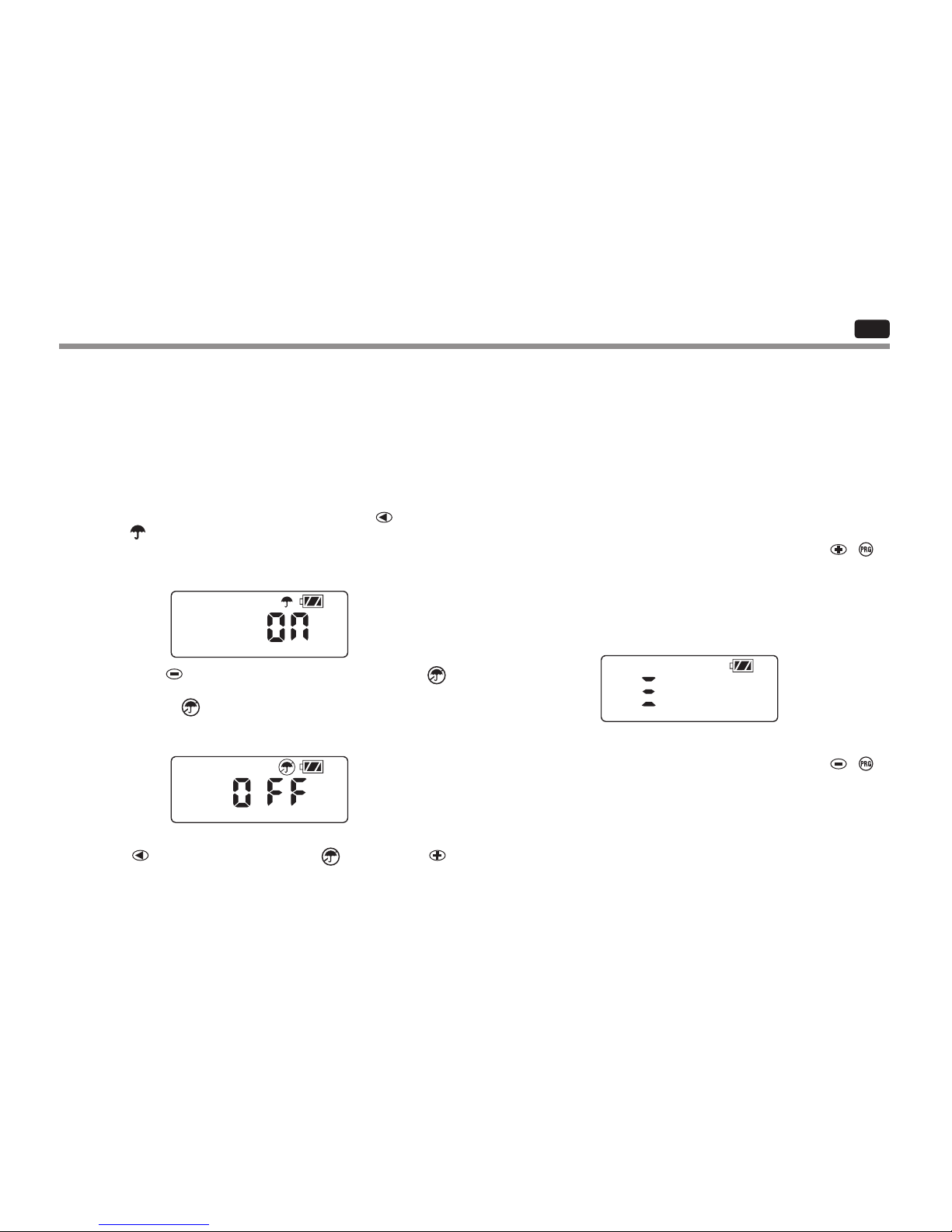
Sensor Bypass
1. From the idle mode, press and hold the button until the icon
is displayed.
2. The display will show the umbrella icon ashing and ON.
3. Press the button to bypass the sensor. The display will show
and OFF to indicate the weather sensor is bypassed.
The
icon will show on the display during normal operation,
indicating the controller is in bypass mode.
4. To reactivate the weather sensor, press and hold the button
until the
icon is displayed. Press the button to return to
normal sensor mode.
Easy Retrieve Memory
This function allows the user to save a preferred program to permanent
memory in the controller, which can be restored at any time. This is a
great way to override changes made, and revert back to the original
programming schedule.
To save a program:
1. Make sure that the controller is programmed with the preferred
programming schedule.
2. From idle mode, press and hold the
and button for ve
seconds to save the current program.
3. The screen will show three dashed lines moving from le to right
to indicate the current program is being saved to permanent
memory. The display will ash DONE when the process is
complete.
To retrieve a saved program:
1. From idle mode, press and hold the
and button for ve
seconds.
2. The screen will show three dashed lines moving from right to
le to indicate the preferred program is being retrieved from
memory.
The controller now has the preferred program as the current program.
The display will ash DONE when the process is complete.
12

EN
ADVANCED PROGRAMMING FEATURES CONTINUED
NOTE: Be careful when using Easy Retrieve
memory. Saving program data to memory using
Easy Retrieve will take the current program
information and override whatever is saved in
permanent memory. When saving program data,
make sure that the current program data is what
you want saved.
Setting Master Valve Operation
(NODE-200, NODE-400, & NODE-600 Only)
The multi-station NODE models (NODE-200, NODE-400, and
NODE-600) can be programmed with the use of a normally closed
master valve. When programming with the master valve you will be
assigning Station 1 as the master valve, eectively losing the use of
Station 1 for activation of an irrigation station.
1. From the idle mode, press the
button until the icon
is displayed.
2. Program A will be displayed along with the active station number
on the lower le. Make sure the active station showing is "1." The
run time will be shown.
3. Press the button once and the MV icon will display on the
screen and the time will disappear. Station 1 is now acting as
the master valve and will not be available in other programming
screens.
4. When the master valve is activated, it will apply to all programs
and the MV icon will stay displayed on the screen at all times.
Programmable O (Up to 99 Days)
This feature permits the user to stop all programmed watering for the
designated period from 1-99 days. At the end of the programmable o
period, the controller will resume normal operation.
1. From idle mode, press the
button until the icon is
displayed. Wait two seconds until OFF is shown on the display.
The controller is now in System O mode.
2. Press the
button and a blinking "1" will be displayed, indicating
the number of days the controller will stay o. Program the o
days as desired, up to 99 days maximum.
3. The display will show the number of days remaining in the
OFF period.
4. To interrupt the OFF period, press the
button to return to the
idle mode screen, showing the time of day and day of the week.
13
EN
The remaining battery life can be estimated from the battery-life
indicator shown on the display. The NODE can operate using either
a single nine-volt battery or using two nine-volt batteries. Using two
nine-volt batteries will yield approximately twice the battery life of a
single nine-volt battery. The battery-life indicator chart below shows
an estimate on the remaining battery life.
Full: 100–60% remaining battery life
Med: 60–25% remaining battery life
Low: 25–0% remaining battery life
Replace battery immediately!
BATTERYLIFE INDICATOR RESETTING CONTROLLER
Resetting the controller will erase the current program data and restart
the controller. A reset does not, however, delete a program saved to
permanent memory using the Easy Retrieve memory feature (see
page 12) to save a preferred program.
1. From idle mode, press and hold the
, , and keys.
2. Aer two seconds the screen will go blank. Continue to hold
the
, , and keys.
3. 12:00 will ash on the display. Release the keys.
4. The controller may show a countdown from 10 to 1 on the display,
and then 12:00 will be shown ashing when the reset is
complete. The controller can now be reprogrammed.
14

EN
SPECIFICATIONS
Dimensions: 3 ½"(89 mm) diameter, 2 ½"(64 mm) high
Sensor inputs: One
Power source: One nine-volt alkaline battery (use two for extended
battery life). Activates DC latching solenoids operating 9-11VDC
(Hunter PN 458200).
Operating temperature: 0ºF to 140ºF
(-17ºC to 60ºC)
Approvals:
IP68
CE
FCC
C-Tick
TROUBLESHOOTING GUIDE
Problem Causes Solutions
There is no display.
Display is o.
Battery is dead.
Press any button for one second.
Replace the battery.
Display indicates watering but
none is occurring.
No water pressure.
Faulty solenoid.
Incompatible solenoid.
Turn on main system supply.
Replace solenoid.
Must use Hunter DC latching solenoid (P/N 458200) or
other compatible DC latching solenoid.
Automatic irrigation does not
start at start time.
Controller in System O mode.
AM/PM/time of day not set correctly.
AM/PM/start time not set correctly.
Verify that controller is programmed for
automatic watering.
Correct AM/PM/time of day.
Correct AM/PM/start time.
Rain sensor does not suspend
watering.
Rain sensor defective or miswired. Verify proper operation of the rain sensor and wire
connections (see page 11).
Controller waters more than one
time.
The program has more than one start time
assigned to it. Each program has up to four
start times.
Eliminate program start times as needed.
15

ESSP
ÍNDICE DE CONTENIDOS
CARACTERÍSTICAS DE NODE ................................................................2
COMPONENTES DE NODE ..................................................................... 3
Botones de control
Pantalla LCD
CONEXIÓN DE LAS PILAS
................................................................4
CONEXIÓN DE SOLENOIDES ................................................................. 5
Cableado de solenoides DC a NODE
Montaje de NODE en una válvula (Figura 1)
MONTAJE DE NODE
............................................................................... 6
CONEXIÓN DE UN SENSOR METEOROLÓGICO ....................................6
Conguración de la fecha y la hora
MODO INACTIVO ...................................................................................7
MODO DE FUNCIONAMIENTO .............................................................. 7
PROGRAMACIÓN ...................................................................................7
Conguración de las horas de inicio de riego
Conguración de los tiempos de riego
Conguración de los días de riego
Selección de días pares/impares de riego
Selección de días de intervalo de riego
Conguración del ajuste estacional
Apagado del sistema
Riego manual
Funcionamiento del sensor
CARACTERÍSTICAS DE PROGRAMACIÓN AVANZADAS
....................12
Bypass del sensor
Memoria Easy Retrieve
Conguración del funcionamiento de la válvula maestra (sólo para
NODE-200, NODE-400 y NODE-600)
Apagado programable (hasta 99 días)
Quick Check de Hunter
INDICADOR DE CARGA DE LA PILA
.....................................................14
RESTABLECIMIENTO DEL PROGRAMADOR .......................................14
GUÍA DE RESOLUCIÓN DE PROBLEMAS .............................................15
ESPECIFICACIONES ..............................................................................16
NOTAS ....................................................................................................17
1

ES
CARACTERÍSTICAS DE NODE
• Programación sencilla con un botón.
• Modelo de una estación (NODE-100) con solenoides tipo “latch” de CC. También modelos de una, dos, cuatro o seis estaciones disponibles (no
se incluyen los solenoides).
• Gran pantalla de cristal líquido (LCD) con iconos fáciles de entender.
• Opera con al menos una pila alcalina estándar de 9 voltios (use dos piles para una mayor duración de las pilas).
• Tres programas (A, B o C) con hasta cuatro horas de inicio cada uno.
• Tiempos de riego de un minuto hasta seis horas.
• Capacidad de riego manual.
• Indicador de carga de la pila.
• Compatible con sensor de lluvia cableado.
• La memoria no volátil conserva toda la información de programas.
• Ajuste estacional entre 10% y 150%.
• La memoria Easy Retrieve™ permite guardar/recuperar los datos del programa preferido.
• Anulación manual del sensor de lluvia.
• La calculadora de tiempos de riego muestra el tiempo de riego total por programa.
2

ES
COMPONENTES DE NODE
Esta sección proporciona una vista general de algunos de los
componentes del NODE. Cada elemento se describirá detalladamente
en secciones posteriores. Sin embargo, esta sección puede resultar útil
para familiarizarse con las distintas opciones disponibles.
Botones de control
1.
Botón
: Aumenta el elemento seleccionado.
2.
Botón
: Disminuye el elemento seleccionado.
3.
Botón
: Selecciona la función de programación.
4.
Botón
: Desplaza el elemento seleccionado hasta el elemento
siguiente.
5.
Botón
: Desplaza el elemento seleccionado hasta el elemento
anterior.
6.
Botón
: Selecciona el programa (A, B o C).
Pantalla LCD
1.
Pantalla principal
: indica toda la información del programa.
2.
Número de estación
: indica el número de estación que se
está programando.
3.
Número de hora de inicio
: indica el número de hora de inicio que
seestá programando.
4.
Programa
: indica el programa (A, B o C).
5.
Día/hora actual
: aparece cuando se establece el día/hora actual.
6.
Horas de inicio
: aparece cuando se establecen las horas de inicio.
7.
Tiempos de riego
: aparece cuando se establecen los tiempos
de riego. Permite al usuario congurar los tiempos de riego de un
minuto hasta seis horas.
8.
Días de riego
: permite al usuario seleccionar días individuales para
regar o un número seleccionado de días entre riegos (intervalo).
9.
% de ajuste estacional
: permite la programación del ajuste
estacional entre 10% y 150% (el valor por defecto es 100%).
10.
Sistema apagado
: indica que el riego se ha suspendido.
11.
Encendido/apagado manual
: aparece cuando se programa el
riego manual. Permite al usuario activar la estación manualmente.
12.
MV – Indica que la estación uno está congurada a la operación de
válvula maestra (solo disponible en los modelos de dos, cuatro o seis
estaciones)
13.
Estado de la pila
: indica la duración restante de la pila.
14.
Paraguas
: indica que el sensor de lluvia ha suspendido el riego.
15.
Paraguas tachado
: indica que el sensor de lluvia se ha
anulado manualmente.
3
ES
Instalación de las pilas
1. Desenrosque la tapa posterior del cuerpo de NODE para poder
acceder al compartimento de las pilas.
2. Inserte las pilas y conéctelas al programador utilizando el
conector.
3. Asegúrese de que no hay agua en el interior del compartimento
delas pilas.
4. Vuelva a enroscar la tapa posterior en el cuerpo de NODE.
NOTA: Verique que el marcador de sello en la mitad
posterior del NODE se alinee con la mitad frontal para
asegurar la creación de un sello adecuado.
El NODE utiliza una o dos pilas estándar de 9 voltios (no incluidas) para
operar las válvulas y congurar el programador. El programador puede
funcionar usando una sola pila de 9 voltios o dos pilas de 9 voltios. En
condiciones normales, la esperanza de vida útil es de un año con una
sola pila, y dos años cuando se utilizan dos pilas de 9 voltios.
NOTA: NODE tiene una memoria no volátil. Esto
permite que la pila se retire sin perder la
información del programa.
CONEXIÓN DE LAS PILAS
4
Cable común (cables negros)
ES
CONEXIÓN DE SOLENOIDES
El NODE-100 se proporciona con un solenoide conectado al
programador. El NODE-100 se proporciona con un solenoide conectado
al programador. Los programadores multiestación NODE-200,
NODE-400 y NODE-600 operarán hasta dos, cuatro o seis solenoides,
respectivamente. Los solenoides Hunter tipo “latch” de CC (P/N
458200) se pueden instalar fácilmente en todas las válvulas plásticas
de Hunter.
NOTE: Use DC latching solenoids operating between
9-11 VDC. 24 VAC solenoids will not operate with the
NODE.
Cableado de solenoides DC a NODE
1. Conecte los cables negros de cada solenoide al único cable común
(cable negro) de NODE. Asegure todas las conexiones de cables
con conectores estancos.
2. Conecte un cable rojo de cada solenoide al cable de estación
correspondiente (cable rojo) de NODE. Los números de estación se
identican en la supercie de NODE. Asegure todas las conexiones
de cables con conectores estancos.
NOTA: La distancia máxima del cable entre el
solenoide y el NODE es 30 m (100') usando un cable
con un calibre mínimo de 18 AWG (1 mm).
Cable de estación
(cables rojos)
5

Figura 1 Modelo Mini-Clik® de Hunter
Soporte del NODE
NODE se pude montar con facilidad en cualquier válvula de plástico
de Hunter. Una pinza de montaje de válvula especialmente diseñada
permite que la instalación sea sencilla. Se proporciona una cubierta
protectora de goma para evitar que se acumule suciedad en la
supercie de NODE.
Montaje de NODE en una válvula (Figura 1)
1. Atornille el solenoide Hunter tipo “latch” de CC (P/N 458200) en
la tapa de la válvula.
2. Coloque el extremo pequeño abierto del soporte del NODE sobre
el solenoide.
3. Coloque el programador NODE en el extremo grande abierto del
solenoide.
Un sensor de lluvia Hunter Mini-Clik o Rain-Clik cableado se puede
conectar al NODE. El propósito de este sensor es detener el riego si lo
requieren las condiciones meteorológicas.
1. Corte el bucle de cable amarillo acoplado a NODE aproximadamente
en la parte media del bucle.
2. Pele aproximadamente 13 mm (½") de aislamiento de cada cable.
Conecte un cable amarillo en cada uno de los cables del sensor
meteorológico. Puede montar el sensor de lluvia hasta 30 m (100')
del programador NODE (con un cable de calibre mínimo de 18
AWG/1 mm).
3. Asegure las conexiones de cables con conectores estancos.
CONEXIÓN DE UN SENSOR METEOROLÓGICO
NOTA: Cuando el sensor de lluvia cableado está
interrumpiendo el riego, la pantalla mostrará el
ícono de sistema apagado , “OFF” y .
MONTAJE DE NODE
6

ES
MODO INACTIVO
MODO DE FUNCIONAMIENTO
Normalmente, la pantalla del NODE muestra la hora y el día, el día
de la semana, MV (si la opción de válvula maestra está activada)
y el indicador de carga de la pila. Después de un breve período de
inactividad, la pantalla se apagará para conservar carga de la pila.
Presionar cualquier botón despertará al NODE del modo inactivo.
Cuando el programador está operando un programa, los elementos
mostrados en la pantalla incluirán el número de estación, la letra del
programa, el tiempo de riego restante y el ícono intermitente de la
turbina.
The NODE uses standard Hunter controller programming with three
programs (A, B, or C) and four start times per programa. En los
programadores Hunter estándar, se usa un dial para desplazarse por
las funciones de programación; sin embargo, en el NODE se usa el
botón
para crear el programa de riego rápida y fácilmente. Durante
la programación, la parte parpadeante de la pantalla se puede modicar
pulsando los botones
o . Para cambiar algo que no parpadee, pulse
los botones
o hasta que parpadee el elemento deseado.
Conguración de la fecha y la hora
1. Pulse el botón hasta que se muestre el icono .
2. Se mostrarán los cuatro dígitos que representan el año. Utilice
los botones
o para cambiar el año. Pulse el botón para
continuar con la conguración del mes.
3. Los cuatro dígitos se mostrarán con dos dígitos intermitentes a
la izquierda representando el mes. Utilice los botones
o
para cambiar el mes. Pulse el botón
para continuar con la
conguración del día.
4. Solo los dos dígitos de la derecha, que representan el día, se
mostrarán y parpadearán. Presione los botones
o
para cambiar el día. Pulse el botón
para continuar con la
conguración dela hora.
5. La conguración de hora AM/PM/24 horas también se muestra
intermitente. Pulse el botón
o para cambiar el ajuste
de hora a formato AM, PM o24 horas. Pulse el botón
para
continuar con la conguración de la hora.
PROGRAMACIÓN CONTINUACIÓN
7

ES
6. Los cuatro números se muestran con los dos números parpadeantes
a la izquierda, que representan la hora. Utilice los botones
o
para cambiar la hora. Pulse el botón para continuar con la
conguración de los minutos.
7. Los cuatro números se muestran con los dos números parpadeantes
a la derecha, que representan los minutos. Utilice los botones
o
para cambiar los minutos. Al presionar el botón avanzará a la
conguración del año en el Paso 2.
8. Pulse el botón
para continuar con la siguiente función de
programación o para permitir que el programador regrese al modo
inactivo.
Conguración de las horas de inicio de riego
1. Pulse el botón hasta que se muestre el icono .
2. La hora de inicio se mostrará parpadeando, junto con la letra del
programa (A, B o C) y el número de hora de inicio (1, 2, 3o 4) en la
parte superior izquierda de la pantalla. Se pueden congurar hasta
4horas de inicio distintas para cada programa.
3. Utilice los botones
o para cambiar la hora de inicio para el
programa en pantalla. Cada vez que el botón se presione cambiará
la hora de inicio en incrementos de un minuto.
4. Pulse el botón
para añadir una hora de inicio adicional al
programa mostrado. El número de hora de inicio se muestra en
laesquina superior izquierda de la pantalla.
5. Pulse el botón
para añadir horas de inicio a un programa distinto.
6. Pulse el botón
para continuar con la siguiente función de
programación o para permitir que el programador regrese al modo
inactivo.
NOTA: Una vez programado el tiempo de riego
para la última estación, pulse el botón para ver
el tiempo de riego total para el programa.
Conguración de los tiempos de riego
1. Pulse el botón hasta que se muestre el icono .
2. El tiempo de riego se mostrará parpadeando. También se muestra la
letra del programa (A, B o C) y el número de la estación activa en el
lado izquierdo inferior de la pantalla. Presione los botones
o
para cambiar el tiempo de operación de la estación de un minuto a
seis horas.
3. Pulse el botón
para desplazarse a la siguiente estación.
4. Pulse el botón
para añadir un tiempo de riego a otro programa.
5. Pulse el botón
para continuar con la siguiente función de
programación o para permitir que el programador regrese al
modo inactivo.
PROGRAMACIÓN CONTINUACIÓN
8

ES
Conguración de los días de riego
1. Pulse el botón hasta que se muestre el icono .
2. Se mostrará la letra del programa (A, B o C).
3. Las echas señalan los días especícos de la semana en que el riego
se activará. Pulse los botones
o para desplazarse por los días.
4. Pulse el botón
para activar ese día para el programa mostrado,
o bien el botón
para cancelar el riego para ese día. La echa
aparecerá en los días de riego para el programa activo.
5. Pulse el botón
para asignar días de riego para otro programa,
encaso deseado.
6. Pulse el botón
para continuar con la siguiente función de
programación o para permitir que el programador regrese al
modoinactivo.
Selección de días pares/impares de riego
Esta característica utiliza días numerados del mes para el riego,
enlugarde días especícos de la semana.
1. Pulse el botón
hasta que se muestre el icono .
2. Pulse el botón
hasta que el cursor esté sobre ODD (impar)
oEVEN (par) en la pantalla.
3. Pulse el botón
para realizar la selección o el botón para
cancelar los días ODD (impar) o EVEN (par) de riego.
4. Una vez activado el modo ODD (impar) o EVEN (par), será el único
cursor que aparezca en la pantalla.
Selección de días de intervalo de riego
1. Pulse el botón hasta que se muestre el icono .
2. Pulse el botón
hasta que el cursor esté sobre INT (intervalo)
enlapantalla.
3. Pulse el botón
y la cifra 1 parpadeará indicando el número de
días entre riegos.
4. Presione los botones
o para seleccionar el número de días
entre los días de riego (de 1 a 31).
Conguración del ajuste estacional
1. Pulse el botón hasta que se muestre .
2. Pulse el botón
o para aumentar o reducir el valor de ajuste
estacional a partir del valor 100% por defecto (entre un mínimo de 10%
y un máximo de 150%).
PROGRAMACIÓN CONTINUACIÓN
O
INT
9

ES
3. El valor programado del ajuste estacional se aplicará a todos los
programas de riego y se reejará inmediatamente en los tiempos de
riego mostrados. Por ejemplo, si se programan tiempos de riego de
20 minutos, y luego se cambia el ajuste estacional de 100% a 50%, los
tiempos de riego indicados serán de 10 minutos.
Apagado del sistema
Para apagar el programador, pulse el botón hasta que el icono
yOFF (apagado) se muestren en pantalla. Para devolver el programador
al modo de programación automática, pulse el botón
. El programador
inmediatamente volverá al modo de programación automática y mostrará
la hora y el indicador de carga de la pila.
Riego manual
El riego manual permite al usuario probar cada estación o un programa
para un tiempo de riego especicado. El estado del sensor meteorológico
(si se utiliza) se descartará en este modo.
1. Asegúrese de que el programador está en modo inactivo.
Mantenga pulsado el botón
hasta que se muestre el icono .
2. El número de estación aparecerá en el lado inferior izquierdo de
lapantalla junto con el tiempo de riego.
3. Utilice los botones y para seleccionar la estación deseada
ylos botones
y para asignar el tiempo de riego manual para
la estación mostrada.
4. Para activar manualmente un programa, pulse el botón
. La letra
del programa (A, B o C) se mostrará en la pantalla. Si se necesita
un programa distinto, pulse el botón
hasta que se muestre el
programa deseado.
5. Para detener el ciclo de riego manual, pulse el botón
hasta que
el tiempo se reduzca a cero.
6. Pulse el botón
para continuar con la siguiente función de
programación o para permitir que el programador regrese al
modoinactivo.
NOTA:
• Al presionar los botones o cuando una
estación está en funcionamiento en el modo de
riego manual, se modicará el tiempo de riego
para esa estación.
• Al pulsar el botón
cuando una estación está
funcionando en riego manual, se detendrá
el riego de la estación actual y se pasará a la
estación siguiente.
• Al pulsar el botón
cuando una estación está
funcionando en riego manual, se detendrá el
riego de la estación actual y se regresará a la
estación anterior.
PROGRAMACIÓN CONTINUACIÓN
10

ES
PROGRAMACIÓN CONTINUACIÓN
Funcionamiento del sensor
El NODE es compatible con los sensores de lluvia Hunter tipo Clik,
incluyendo los Mini-Clik, Freeze-Clik, y Rain-Click cableado, así
como con muchos otros dispositivos/sensores tipo interruptor que
no requieren corriente. Basta con conectar el sensor al programador
NODE cortando el bucle de cable amarillo yconectándolo a los cables
del sensor.
NOTA: NODE no es compatible con Wireless
Rain-Clik® de Hunter ni con otros dispositivos
meteorológicos que necesiten alimentación
de24VCA.
Una vez activado el sensor, suspenderá el riego y el icono aparecerá
en la pantalla.
11
ES
CARACTERÍSTICAS DE PROGRAMACIÓN AVANZADAS
Todas las funciones de programación avanzada se inician desde el
modo inactivo, que muestra la hora, el día de la semana y el indicador
de carga de la pila en la pantalla. Si en la pantalla algún elemento
parpadea, signica que el programador está en uno de los modos
de programación. Después de un corto período de inactividad, el
programador regresa al modo inactivo.
Bypass del sensor
1. En el modo inactivo, mantenga presionado el botón hasta que
el ícono
se muestre en la pantalla..
2. En la pantalla aparecerá el icono de paraguas parpadeando y ON
(encendido).
3. Pulse el botón para anular el sensor. La pantalla mostrará
y OFF para indicar que el sensor meteorológico está actualmente
anulado. El icono
aparecerá en la pantalla durante el
funcionamiento normal, lo que indica que el programador está en
modo de bypass.
4. Para reactivar el sensor meteorológico, mantenga pulsado
el botón
hasta que se muestre el icono . Pulse el botón
para regresar al modo normal de sensor.
Memoria Easy Retrieve
Esta función permite al usuario guardar un programa preferido a la
memoria permanente en el programador, el cual se puede restaurar
en cualquier momento. Se trata de una manera muy útil de anular los
cambios realizados y regresar a la programación original.
Para guardar un programa:
1. Asegúrese de que el programador está programado con la
programación preferida.
2. En el modo inactivo, mantenga presionados los botones
y
durante cinco segundos para guardar el programa actual.
3. La pantalla mostrará tres líneas punteadas que avanzan de
izquierda a derecha para indicar que el programa actual se está
guardando a la memoria permanente. En la pantalla parpadeará
DONE (terminado) cuando nalice el proceso.
Para recuperar un programa guardado:
1. En el modo inactivo, mantenga presionados los botones
y
durante cinco segundos.
2. La pantalla mostrará tres líneas punteadas que avanzan de
derecha a izquierda para indicar que el programa actual se está
recuperando de la memoria permanente.
Al terminar el programador tendrá el programa preferido como
programa actual. En la pantalla parpadeará DONE (terminado) cuando
nalice el proceso.
12

ES
CARACTERÍSTICAS DE PROGRAMACIÓN AVANZADAS CONTINUACIÓN
NOTA: Preste atención al utilizar la memoria
EasyRetrieve. Al guardar datos de programa en
lamemoria utilizando Easy Retrieve se utilizará la
información del programa actual y se anulará todo
loguardado en la memoria permanente. Al guardar
datos de programa, asegúrese de que la información
del programa actual es la que desea guardar.
Conguración del funcionamiento de la válvula maestra
(sólo para NODE-200, NODE-400 y NODE-600)
Los modelos NODE multiestación (NODE-200, NODE-400, y
NODE-600) se pueden programar por medio de una válvula maestra
normalmente cerrada. Al realizar la programación de la válvula maestra
se asignará la estación 1 como válvula maestra, lo que provocará que
se pierda de forma efectiva el uso de la estación 1 para la activación de
una estación de riego.
1. En el modo inactivo, presione el botón
hasta que el ícono
se
muestre en la pantalla.
.
2. El programa A se mostrará junto con el número de la estación
activa en la parte izquierda inferior. Asegúrese que la estación
activa indicada sea "1".
Se mostrará el tiempo de riego.
3. Pulse el botón una vez para que el icono MV aparezca en la
pantalla y el tiempo desaparezca. A partir de ahora la estación
1 actúa como la válvula maestra y no estará disponible en otras
pantallas de programación.
4. Cuando la válvula maestra se activa, lo hará en todos los programas
y el icono MV se mantendrá en pantalla en todo momento.
Apagado programable (hasta 99 días)
Esta característica permite al usuario detener todos los riegos
programados durante un período designado de entre 1 y 99 días.
Alnal del período de apagado programable, el programador
reanudará elfuncionamiento normal.
1. En el modo inactivo, presione el botón
hasta que el ícono
se muestre en la pantalla.
Espere dos segundos hasta que OFF
(apagado) se muestre en la pantalla. El programador pasa el modo
de sistema apagado.
2. Presione el botón
y se mostrará un "1” intermitente, lo que
indica el número de días que el programador permanecerá
apagado. Programe los días de apagado según sus necesidades,
con un máximo de 99 días.
3. En la pantalla se mostrará el número de días restantes del
periodo OFF (apagado).
4. Para interrumpir el período de apagado, presione el botón para
regresar a la pantalla de modo inactivo, que muestra la hora del
día y el día de la semana.
13

La carga restante de la pila se puede calcular con el indicador de carga
de la pila que se muestra en la pantalla. El NODE puede funcionar
usando una sola pila de 9 voltios o dos pilas de 9 voltios. El uso de dos
pilas de 9 voltios rendirá aproximadamente el doble de tiempo que una
sola pila de 9 voltios. La tabla del indicador de carga de la pila muestra
un estimado de la carga restante de la pila.
Completa: 100–60% de duración restante de la pila
Media: 60-25% de duración restante de la pila
Baja: 25-0% de duración restante de la pila
¡Sustituya la pila inmediatamente!
INDICADOR DE CARGA DE LA PILA
RESTABLECIMIENTO DEL PROGRAMADOR
Al restablecer el programador se borrarán los datos del programa
actual y se reiniciará el programador. Sin embargo, un restablecimiento no elimina un programa guardado en la memoria permanente
utilizando la característica de memoria Easy Retrieve (consulte la
página 12) para guardar un programa preferido.
1. En el modo inactivo, mantenga presionadas las teclas
, y .
2. Transcurridos dos segundos, la pantalla se quedará en blanco.
Continúe pulsando las teclas
, y .
3. 12:00 parpadeará en la pantalla. Suelte las teclas.
4. Es posible que el programador muestre una cuenta atrás de
10 a 1 en la pantalla y, a continuación, se mostrará 12:00
parpadeando cuando nalice el restablecimiento. Ahora el
programador se puede reprogramar.
14
 Loading...