

Page 1

IDS
Decoder Controller
Two-wire Decoder Control
in an Advanced Industrial
Package for the Largest
Installations
Programming and
Operations Manual
®
Page 2

Page 3

TABLE OF CONTENTS .....................................................
Introduction .......................................................................................................................................................... 1
How IDS Works............................................................................................................................................... 1
Field Controller Programs..................................................................................................................................... 1
IDS Option & Settings Displays............................................................................................................................. 2
Programming and Operations ...............................................................................................................................3
Emergency Functions (OFF and Pause).............................................................................................................3
OFF................................................................................................................................................................. 3
Rain Shutdown................................................................................................................................................ 3
Pause .............................................................................................................................................................3
Controller Setup ...................................................................................................................................................4
Field Controller Settings .................................................................................................................................. 4
Set Address ....................................................................................................................................................6
Set Time ......................................................................................................................................................... 6
Set Date.......................................................................................................................................................... 6
Set Main % Scale ............................................................................................................................................ 7
Set Schedule Length........................................................................................................................................ 7
Set Schedule Day ............................................................................................................................................ 7
Set Day Change...............................................................................................................................................8
Set FCP Inhibit ................................................................................................................................................ 8
Set Response.................................................................................................................................................. 9
Set MR Runtime.............................................................................................................................................. 9
Set MR Pump................................................................................................................................................ 10
Set PINs .......................................................................................................................................................10
Writing a Field Controller Program ..................................................................................................................... 11
Naming a Program ........................................................................................................................................ 11
Typing Instructions ....................................................................................................................................... 11
Assigning a Schedule to a Field Controller Program........................................................................................ 11
Assigning a Start Time to a Field Controller Program ...................................................................................... 13
Programming Stations: Run Times, Events, and Blocks................................................................................... 14
To Program Individual Stations ...................................................................................................................... 14
Blocks .......................................................................................................................................................... 16
Station Options (Changing Events) ................................................................................................................ 18
Program Advanced Options................................................................................................................................. 21
Edit Program Name ....................................................................................................................................... 21
Set Program % Scale .................................................................................................................................... 21
Cycles........................................................................................................................................................... 21
Cycle Delay ................................................................................................................................................... 22
Skip Days ..................................................................................................................................................... 23
Pump............................................................................................................................................................ 24
End Time ......................................................................................................................................................24
Manual Starts ..................................................................................................................................................... 25
Semi-Automatic Program Operation.................................................................................................................... 26
To Semi-Automatically Start a Program .......................................................................................................... 26
Presets ............................................................................................................................................................... 27
To Create a Preset .........................................................................................................................................27
Page 4

TABLE OF CONTENTS (CONTINUED) .....................................
To Start a Preset ........................................................................................................................................... 28
Field Controller Advanced Options...................................................................................................................... 28
Remove a Program........................................................................................................................................ 28
Remove Preset.............................................................................................................................................. 29
Edit Decoders................................................................................................................................................ 29
View SYS Events ........................................................................................................................................... 30
Remove SYS Events ...................................................................................................................................... 30
Radio Transmit (Xmit) Test ............................................................................................................................ 30
Maintenance Radio Operations (Optional) .......................................................................................................... 31
Maintenance Radio Commands ...................................................................................................................... 31
Sending a Maintenance Radio Command ........................................................................................................ 31
Central Control Options ...................................................................................................................................... 32
Maintenance Radio Functions & Commands........................................................................................................ 33
Display Messages (Status, Errors & Other Conditions)........................................................................................ 34
Status Displays ............................................................................................................................................. 34
Other Messages ............................................................................................................................................34
IDS Series Specifications ...................................................................................................................................36
IDS Troubleshooting and Frequently Asked Questions ......................................................................................... 37
Index .................................................................................................................................................................. 38
Page 5

INTRODUCTION ...............................................................
IDS is a unique, standalone irrigation controller, using
only a single twisted-pair of wires (or “path”) to operate up to 103 decoder stations. IDS actually provides
five two-wire paths to permit efficient wiring in several
directions.
How IDS Works
Decoders operate 24VAC valve solenoids to turn on
irrigation. The decoders are installed along a two-wire
path, and the IDS controller sends both power and
signals over the same two wires.
Each decoder has a unique 8-digit Serial Number,
printed on the side of the decoder. The decoder Serial
Numbers are assigned to controller station numbers
by the system operator (either from the keypad, or the
optional IDSCD Decoder Manager software). This unique
ID number is used to signal the decoder that IDS wants
to operate.
IDS operates both single and multi- station decoders.
The ID4 decoder has four independently addressable
station outputs (the decoder has a 7-digit number,
followed by a 1, 2, 3, or 4, to indicate each station).
Decoder systems should also include grounded surge
protection modules in the two-wire paths, although they
are not programmable and are not addressed by
the controller.
Two Controllers in One: The IDS actually has two different “brains” for storing and running two different kinds
of irrigation programs. The keypad on the controller
can create and run Field Controller Programs. The other
type of programming is generally not used in IDS, but
is designed to accept downloaded station events from a
very specialized central computer.
Field Controller Programs (FCPs) are the Programs
numbered 1 through 64, which you can write from
the keypad. You can change them in the field at any
time. They will run at the start times you specify and
do exactly what you tell each one to do. Most of this
manual is concerned with configuring and operating
FCPs through the keypad. There are also some references to System Events (sometimes shown as SYS).
These references are explained, but generally not used.
FIELD CONTROLLER PROGRAMS ................................
Field Controller Programs, or FCPs, are the irrigation
programs used for daily irrigation. They can also be
started by an operator whenever irrigation is desired.
There are 64 programs which can be divided up any way
you want. Each FCP may have up to 30 events, and can
be programmed to cycle (or repeat) up to 15 times, or
continuously. FCPs are also permitted to overlap, meaning that more than one program (up to 20, in fact) can
operate at once.
1
Page 6

IDS OPTION & SETTINGS DISPLAYS ...........................
Options
(Press Options button
from time/ date display)
Pause Watering
List FC Settings
Edit FC Settings
Block Programming
Create
Edit
Remove
Remove Program
Remove Preset
Edit Decoders
View SYS Events
Rem SYS Events
Radio Xmit Test
( Radio controllers only)
Edit FC Settings
(From Options, Edit FC
Settings)
Address
Time
Date
Main % Scale
Schedule Length
Schedule Day
Day Change
FCP Inhibit?
Response
MR Runtime
MR Pump
PINs
EXIT OFF
PROGRAM
SELECT
SCHEDULE
Program Advanced
Options
(Options when a Program
or Preset name is
selected)
Edit Program Name
Set Program % Scale
Cycles
Cycle Delay
Skip Days
Pump
End Time
IDS
STATIONS OPTIONS
Schedule Options
(Options when Schedule
is selected)
Daily (up to 31-day
schedule)
Day of Week
(SMTWTFS)
Station Options
(Options when a Station
is selected)
Remove Event
Cluster Events
Move Event
Insert Event
PRESETS
MANUAL
START
NEXTBACK
1. Stops all irrigation; enables and disables Rain
Shutdown.
2. Sets run times and order for stations and Blocks.
3. Accesses multiple options and controller settings.
Different sets of options appear, depending on mode
controller is in (with other keys).
4. Saves field inputs and edits.
5. Selects between fixed choices in the display, and
selects Rain Shutdown yes/no when OFF
is pressed.
6. Alphanumeric buttons for data entry.
7. Clears display error messages; erases Program
Name in Edit mode.
8. Determines type of schedule and actual water days
On/Off for the selected Program.
123
abc def
456
ghi jkl mno
789
pqrs tuv
CLEAR
wxyz
ENTER
TOGGLE
0
9. Navigate backward/forward through displays, Programs, and Option choices.
10. Defines Start Time for automatic Programs;
launches Preset programs immediately.
11. Starts one or more stations immediately.
12. Cycles through available Preset names, allows
access for creation or editing, or immediate start
with Start button.
13. Cycles through available Program names, allows
access for creation or editing, or immediate start
with Start button.
14. Escapes current function and exits to next
highest level.
2
Page 7

PROGRAMMING AND OPERATIONS ...........................
Note: The IDS keypad display has a built-in timer and
will automatically exit any programming mode after 3
minutes if left untouched. If you are using the password
protection feature, you will be required to log back in
once this has happened. Any data not saved will be lost
if the controller auto-exits.
Emergency Functions ( OFF and Pause)
EXIT OFF
IDS
PROGRAM
SELECT
PRESETS
MANUAL
START
NEXTBACK
OFF: If you need to stop all irrigation at a controller
immediately, press the OFF button to the right of the
display. You may see a brief message, STOPPING ALL
IRRIGATION, followed by:
EXIT OFF
Rain Shutdown: Rain Shutdown turns off all automatic
functions permanently, until a human operator manually
removes the controller from the Rain Shutdown mode
(from the IDS keypad or a central computer). If you
want to enter the Rain Shutdown mode, press ENTER.
The display will show:
SCHEDULE
STATIONS OPTIONS
123
abc def
456
ghi jkl mno
789
pqrs tuv
CLEAR0TOGGLE
wxyz
ENTER
To turn off Rain Shutdown (and restore the controller to
automatic operations): When the display shows RAIN
SHUTDOWN!, press OFF. The display will show:
EXIT OFF
Press ENTER, and the controller will return to the
automatic mode.
Pause: The IDS controller features dynamic pause,
which will suspend all irrigation at the controller temporarily. This will apply to manual, semi-automatic, automatic and Preset Programs. The irrigation will remain
paused until resumed by a human operator or until 30
minutes have elapsed. The controller will resume irrigating where it left off. Note that Pause will cause the end
of the “water window” to be ignored – the end time of
the paused Program will be pushed back for the duration of the Pause.
EXIT OFF
IDS
PROGRAM
SELECT
PRESETS
MANUAL
START
NEXTBACK
To Pause a Controller: Press OPTIONS. The display
will show:
EXIT OFF
SCHEDULE
STATIONS OPTIONS
123
abc def
456
ghi jkl mno
789
pqrs tuv
CLEAR0TOGGLE
wxyz
ENTER
EXIT OFF
You will have to remember to place the controller
back into automatic operation when irrigation is
required again.
If you do not want to enter Rain Shutdown, press the
OFF button again (upper right of the keypad) or any
other button except ENTER. This will simply shut down
all current irrigation until the next scheduled Start Time.
Note that if another automatic Program was scheduled
to start one minute later, the controller will begin irrigating again in one minute.
Press ENTER to select the Pause option. The display
will show:
EXIT OFF
“YES” will be capitalized. To Pause the controller, press
ENTER. The display will then show:
EXIT OFF
This will Pause all irrigation at the controller.
3
Page 8

PROGRAMMING AND OPERATIONS (CONTINUED)............
To resume watering, press ENTER while the display
says Resume Watering? The display will then show:
EXIT OFF
Press ENTER with YES capitalized, and the controller
will resume irrigating where it left off when you paused
it. No irrigation will be missed, only delayed. After 3
minutes, the Resume Watering? display will disappear, but the display will continue to flash PA U SE with
the amount of time left to automatic resume. Press
OPTIONS to return to the Resume Watering? dis-
play.
Note that if the controller was paused for 20 minutes,
the currently active and any subsequent stations will be
moved back in time 20 minutes.
If the Program would normally have ended at 5:30 AM, it
would now end at 5:50 AM.
If you forget to Resume irrigation after placing the
controller into Pause, it will automatically resume after
30 minutes. (The “no” selections will be in lower case.
Press the TOGGLE button to switch between YES and
NO. If you do not want to pause/ resume the irrigation,
TOGGLE to NO and press ENTER, or simply press
EXIT.)
Also, if the optional End Time has been set for any
program(s), it is possible to Pause before a program
has reached its End Time, and then Resume after the
End Time. In this unlikely (but possible) event, the
program would finish irrigating with the current Cycle
(even though the End Time has elapsed), but would not
start any additional Cycles. End Times have no effect
on Manual starts (which will always Resume and finish
normally).
CONTROLLER SETUP ......................................................
Setting up an IDS controller can be very simple. There
are a few essential steps to get a controller running
your programs, once it is installed and connected to the
decoders. The bare minimum steps are:
• Set the controller’s time and date
• Assign individual stations to decoder serial
numbers (see Edit Decoders)
• Create a Program
• Set up a Day Schedule
• Set up a Start Time
• Assign Stations and station Run Times to the Program
Following are in-depth descriptions of all controller
functions, but if you complete the basic steps above,
you are ready for automatic irrigation.
When you start up a brand new IDS controller, or if you
have erased the controller memory and are reprogramming from scratch, you must set up some basic operating information first.
Field Controller Settings
Press the OPTIONS button. The display will show
“ Pause Watering?” Press the OPTIONS button
again. The display will show “List FC Settings?” (“FC”
always means “Field Controller”). Press ENTER. The
display will automatically sequence the current information for the field controller in the following format:
Version Number: The version of field controller software
installed in the IDS. Note the version number whenever
possible, before calling Hunter or your Distributor with
technical issues.
Time: On start up, this may be incorrect, but it will
show the time of day that IDS thinks it is.
Date: On start up, this may be incorrect, but it will show
the day of week and year that IDS thinks it is.
Size: Controller should be configured to 103 stations.
System Address: The unique identification number
for a particular IDS controller in an optional central
system. You may leave this set to “0” for standalone
IDS operations.
Main Percent Scale: Indicates that the controller will
operate each station for 100% of its scheduled
Run Time.
Schedule Length: An IDS may be programmed on a
multiple day schedule (from 1 to 31 days). This shows
the actual schedule length of the controller.
4
Page 9

CONTROLLER SETUP (CONTINUED) ......................................
Day of Schedule: This shows which day (of the schedule in the previous setting) that the controller thinks
it is.
Day Change: The time at which the schedule day
changes. The default is midnight, but you may change
the time to any hour of the day.
Prg Inhibit is OFF: This setting is only meaningful
in central systems, and shows the status of the Field
Controller Programs (FCPs). If they have been inhibited, they will not run. In IDS controllers, inhibit should
always be set to “ OFF”.
The following items will only appear if the controller has
an Address set (to some number other than “0”):
System Response: This setting is only meaningful in
central systems, and shows how much communicating
the IDS controller will perform with a central computer.
System Event Day: This feature is not used in IDS
controllers. This is only used in central systems which
calculate “look ahead” schedules and download them to
the controller.
LineOn : 280ma
The actual milliamp measurement will vary, and partly
depends on whether any stations are operating. The
standby draw usually starts around 0-100ma, depending
on temperature, but each decoder in- line will add about
1 milliamp on a standby basis. As decoders are activated, they will add approximately 20ma per solenoid to
the line draw.
If you continue to press the OPTIONS button, you will
cycle through all of the available controller options:
Pause Watering? Stops irrigation temporarily; restarts
where it left off (with Resume command).
List FC Settings? Automatically displays vital Field
Controller settings.
Edit FC Settings? Allows you to change vital Field Controller settings.
Block Prgraming? Allows you to group multiple stations into a single block for programming purposes. See
Blocks on page 16.
System Day Change: This feature is not used in IDS
controllers. It is a day change time that is downloaded
from a central computer, and is not the same as the
controller’s Day Change time setting.
Maint Radio Run Time: This is the default time-out for
stations started with a Maintenance Radio without a run
time specified. If you forget to turn the station off, IDS
will turn it off for you in 30 minutes.
Maint Radio Pump: This specifies whether the Pump
output turns on whenever a station is started by a Maintenance Radio command.
After the above status messages, the final display
will be:
Ctrl Uptime: The length of time this controller has been
operating since the last time the power was turned on,
or restored after a power outage. This is displayed in
days, hours, minutes and seconds.
When the controller has finished sequencing through
the FC Settings, it will show the current day and time,
and power draw. There may be a “ POWER OUTAGE”
message flashing in the display. Press the CLEAR
button to clear this message.
Remove Program? Allows you to delete a single program, including all station run times.
Remove Preset? Allows you to delete a single Preset,
including all station run times.
Edit Decoders? Allows setup and/or changes to
decoder/ station assignments.
View SYS Events? Not used in IDS. Allows view of
downloaded System Program events.
Del SYS Events? Not used in IDS. Allows deletion of
downloaded System Program events.
Radio Xmit Test? ( Radio controllers only) Generates a
5-second test tone for diagnostics.
Edit FC Settings: Of all the Field Controller options, this
is the most vital to set up on a new installation. Many
of the powerful features of IDS will not work, or will not
work as intended, until these settings are made.
Press OPTIONS 3 times and the display will show
“ Edit FC Settings?” In this menu, you are able to
change many of the settings displayed in the “List FC
Settings” menu above.
On the line beneath the time, the display will also show
“ LineOn” followed by the current draw, in milliamps:
Press ENTER, and the display will show “Set
Address?”
5
Page 10

CONTROLLER SETUP (CONTINUED) ......................................
You may now press ENTER, to set or change the
Address, or press OPTIONS again, to view further set-
tings. You can also use the BACK and NEXT buttons
to move backward and forward through the settings.
Whenever the display shows a setting you want to
change, press ENTER to edit it.
Set Address
A standalone IDS controller does not need an address
(it may be left at “0”). However, the IDS Field Controller
cannot communicate with a Maintenance Radio or a central system until it has an Address. Each controller must
then have a unique 3-digit number, so that the central
interface and/or Maintenance Radio can direct communications to the correct controller. If you need to set
an address, when the display shows “Set Address?”,
press ENTER. The display will show:
The current am/pm selection will be capitalized.
The other selection will be in lower case. Press the
TOGGLE button to switch between AM and PM. When it
is correct, press ENTER. The display will show:
Press ENTER to set the time. The display will briefly
show SAVED! and the time you have set. After a
moment, the display will revert to:
EXIT OFF
EXIT OFF
EXIT OFF
EXIT OFF
Type the address you want with the number buttons on
the keypad and press ENTER. The display will show
“SAVED! Address = 2” (example).
The address is now saved. You can use any 1, 2, or
3-digit number, and controllers in a central system do
not need to be sequentially numbered. However, each
controller must have a unique address. If more than one
controller has the same numeric address, the system
will become confused and errors will occur.
Once the address is set, you may use the OPTIONS,
BACK, or NEXT buttons to view more options, or you
may press EXIT to leave the Edit Settings mode.
Note: If you set an address in a standalone controller,
when no central system is present, the display will show
the message “No Network Link” after a few minutes.
This is normal and will not affect irrigation. It simply
indicates that no central system has been heard from.
You may now press the OPTIONS, BACK, or NEXT
buttons to view more options, or you may press EXIT
to leave the Edit Settings mode.
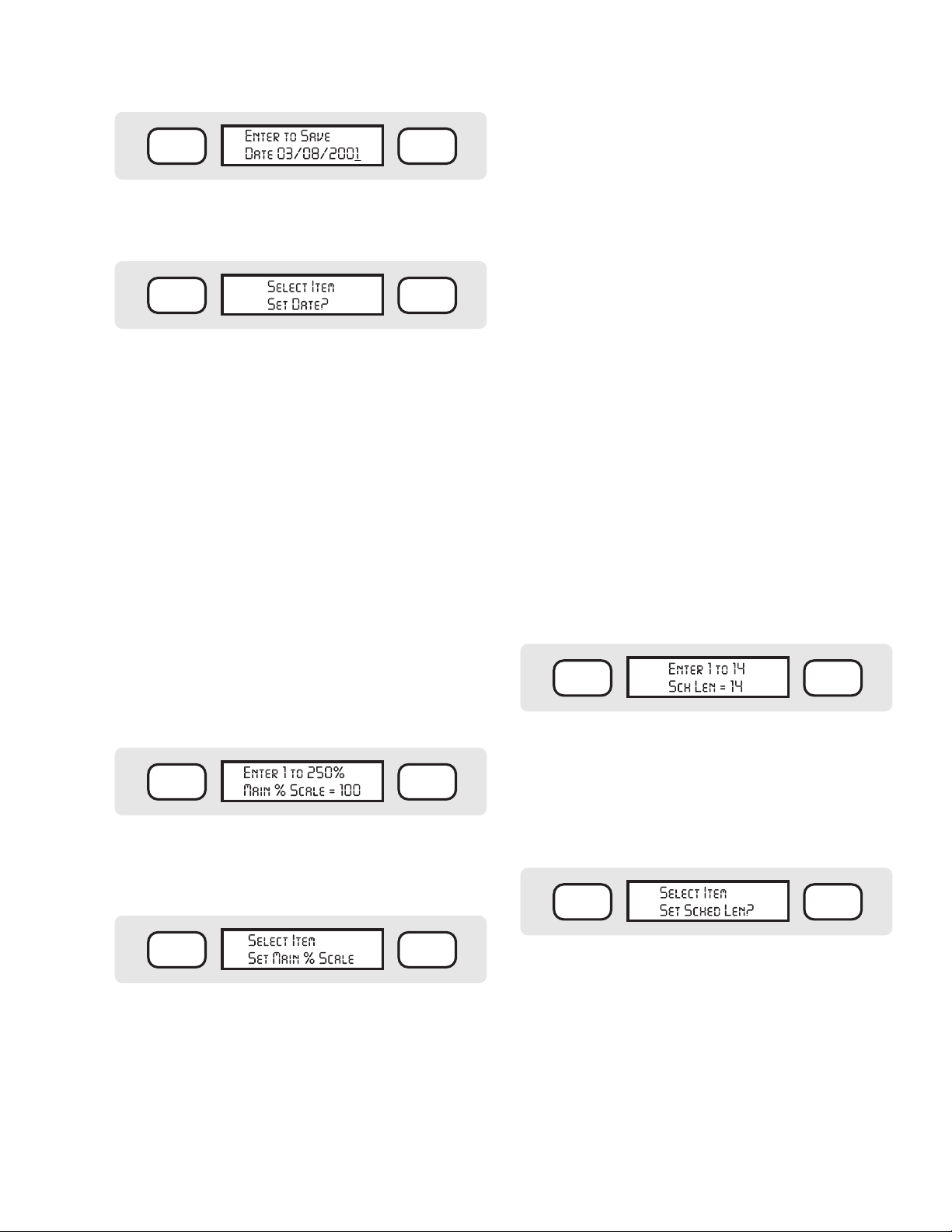
Set Date
To set the Date, press ENTER at this display. The display will then show:
EXIT OFF
Note: IDS dates are always shown in North American
format (month/day/year).
Type the number for the correct month (1-12), in this
case “3” for March, and press ENTER (you can also
use the BACK/NEXT buttons to move around in the
Date). The display will then show:
EXIT OFF
Set Time
To set the time, press ENTER. The display will show:
EXIT OFF
Type the correct time (1:15, for example, in hour, then
minute format), and press ENTER. The display
will show:
6
Type the number for today’s date (“8” in this example),
and press ENTER. The display will show:
EXIT OFF
Type the correct year, and press ENTER. The display
will show:
Page 11
EXIT OFF
Press ENTER to set the date. The display will briefly
show SAVED! and the date you have set. After a
moment, the display will revert to:
EXIT OFF
You may now press the OPTIONS, BACK, or NEXT
buttons to view more options, or you may press EXIT
to leave the Edit Settings mode.
Set Main % Scale
“ % Scale” allows you to reduce or increase all of the
Run Times in the controller by the selected percentage
(from 1 to 250%, in 1% increments). This enables you
to quickly adjust the amount of irrigation for weather or
other conditions without changing the basic programs.
At 50%, each Run Time will only run half as long, and
at 150%, each Run Time will run one-and-half times
as long.
Note: In the Program Options, you can also scale individual Programs separately. The effects of % scaling are
cumulative. See Set Program % Scale on page 21.
Once the Main % Scale has been changed, the scaled
run times for all stations will be displayed when the Stations button is pressed in any Program. To return to the
original (or base) run times, repeat the procedure above
and change the Main % Scale to 100%.
Set Schedule Length
The Schedule Length is the number of days in a complete IDS watering period, and allows the controller to
track programs which do not water every day. If you
only water a certain plant type every other day, for
example, you could enter a 2-day Schedule, and schedule that program to water on just one of the days. The
Schedule Length is tracked for the entire controller. To
set the watering Schedule for individual programs, go
to the individual Program and press SCHEDULE (see
Schedule on page 11).
If you are not sure what schedule you need, start out
with a 7-day schedule (so that it matches the number of
days in a calendar week). You can always change it later.
If you always water everything every day, you can also
just set a 1- Day schedule.
To Set the Schedule Length: Press ENTER at the “Set
Sched Len?” display. The display will then show:
EXIT OFF
To set the Main % Scale from the Edit FC Settings mode,
press ENTER at this display. The display will show:
EXIT OFF
Type the percentage you want with the number buttons
on the keypad, and press ENTER. The display will
briefly show “SAVED!” and the new % Scale amount.
After a moment, the display will revert to:
EXIT OFF
You may now press the OPTIONS, BACK, or NEXT
buttons to view more options, or you may press EXIT
to leave the Edit Settings mode.
Note that whenever the controller is scaled up or down
(to any value other than 100%), a “+” or “-” sign will
appear as a reminder in the upper left corner of the
status display (before the Day and Time information).
The default Schedule Length (the way IDS comes “out of
the box”) is 14 days: the maximum is 31 days. Type the
number of the new Schedule Length (any number from
1 to 31) with the number buttons on the keypad, and
press ENTER. The display will briefly show “SAVED!”
and the new Schedule Length selection. After a moment,
the display will revert to:
EXIT OFF
You may now press the OPTIONS, BACK, or NEXT
buttons to view more options, or you may press EXIT
to leave the Edit Settings mode.
Set Schedule Day
The Schedule Day shows which day of the Schedule
the controller thinks it is. For example, if you had set
a 7-day schedule for a Schedule Length (above), you
could tell the controller that today is Day 1 of the 7-day
schedule, meaning Sunday. If today happens to be
7
Page 12
CONTROLLER SETUP (CONTINUED) ......................................
Wednesday, you could tell it that today is Day 4 (of the
7-day schedule).
Another example would be if most of your irrigation
occurred every day, but a few programs only run every
other day (regardless of the day of the week). You
could set up a 2-day Schedule Length, and then tell the
controller which of the two days today is (1 or 2). In the
Program Schedule (see Schedule on page 11) you can
specify which days the individual Programs will water.
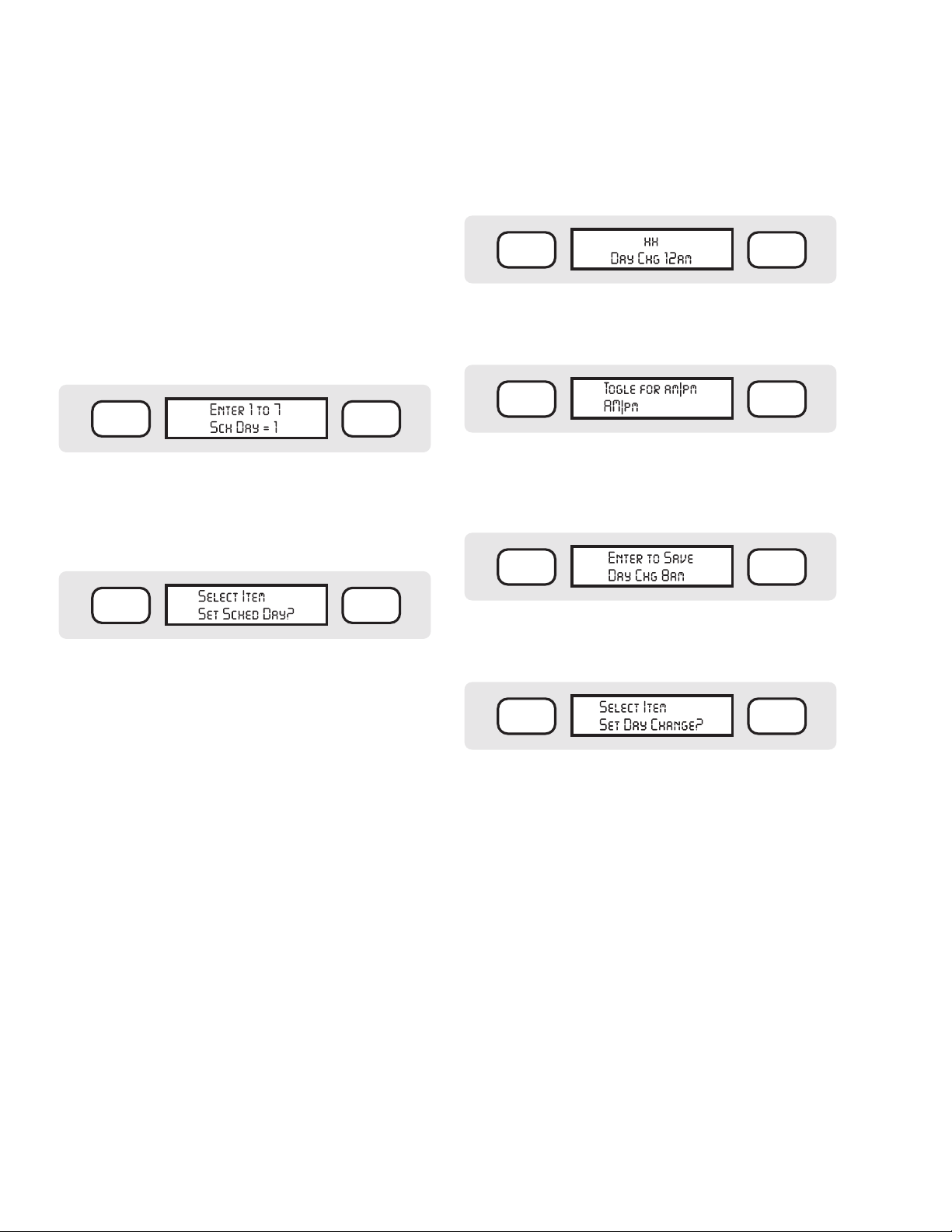
To Set the Schedule Day (for today): Press ENTER
at the “Set Sched Day?” display. The display will
then show:
EXIT OFF
Type the number of the new Schedule Day with the
number buttons on the keypad, and press ENTER.
The display will briefly show “SAVED!” and the new
Schedule Day selection. After a moment, the display will
revert to:
You may only set the Day Change to an exact hour (no
minutes).
To Set the Day Change: Press ENTER at the “ Set Day
Change?” display. The display will then show:
EXIT OFF
Type the number for the Day Change hour (8, in this
example) with the number buttons on the keypad, and
press ENTER. The display will show:
EXIT OFF
The current selection will be capitalized. Other selections will be in lower case. Press the TOGGLE button
to switch between AM and PM. When it is correct, press
ENTER. The display will show:
EXIT OFF
EXIT OFF
You may now press the OPTIONS, BACK, or NEXT
buttons to view more options, or you may press EXIT
to leave the Edit Settings mode.
Set Day Change
The programmable Time of Day Change option allows
you to tell the controller at what time one day changes
into another, when using the Daily Schedule option.
The default is, of course, midnight (12 AM). However,
this occurs right during the middle of many nightly
“water windows”. If you water a certain schedule every
other day, and the irrigation spans across midnight, you
may lose the irrigation programs which technically fall
on a non-irrigation day (past midnight).
To prevent this and similar confusion, you may specify
a different hour for your irrigation days to change. Usually this is done after all irrigation is completed. If your
night’s irrigation is completed by 7 in the morning, you
might wish to set the Day Change to 8:00 AM. Then, all
of your irrigation will fall within a single “irrigation day.”
Note: Time of Day Change only applies to Daily schedules. Day of Week schedules (Monday, Tuesday, etc.)
always change at midnight.
Press ENTER to set the Day Change. The display will
briefly show SAVED! and the time of Day Change hour
you have set. After a moment, the display will revert to:
EXIT OFF
You may now press the OPTIONS, BACK, or NEXT
buttons to view more options, or you may press EXIT
to leave the Edit Settings mode.
Set FCP Inhibit
FCPs (Field Controller Programs) are the Programs
numbered from 1 through 64 in the Field Controller. This
setting is normally not used in IDS, and should be left at
“ OFF”. (The controllers may also irrigate with a master
system program from a central computer. FCP Inhibit
will prevent all of the numbered FCPs from running.)
Remember that FCP Inhibit on means the FCPs will
not run. FCP Inhibit set to off means the FCPs will run
normally.
To Set FCP Inhibit: Press ENTER at the “Set FCP
Inhibit?” display. The display will then show:
8
Page 13

EXIT OFF
The display will flash “SAVED!” and your selection.
After a moment, the display will revert to:
The current selection will be capitalized (default is
OFF). The “on” selection will be in lower case. Press
the TOGGLE button to switch between OFF and ON.
When it is correct, press ENTER. The display will flash
“SAVED!” and your selection. After a moment, the
display will revert to:
EXIT OFF
You may now press the OPTIONS, BACK or NEXT
buttons to view more options, or you may press EXIT
to leave the Edit Settings mode.
Set Response
This setting is normally not used in IDS. It sets the level
of Field Controller response to a central computer (if it
is present and communicating).
The default setting is to “NONE”. The controller can
also be set to “PARTIAL” or “FULL.”
In the Partial Response setting, the field controller will
report any alarm conditions (such as Fuse Open, Overload, Power Outage, etc.) to a central system. In the
Full Response setting, the Field Controller will report all
events as they occur, including every station start and
station stop, as well as alarms.
You may now press the OPTIONS, BACK, or NEXT
buttons to view more options, or you may press EXIT
to leave the Edit Settings mode.
EXIT OFF
Set MR Runtime
MR = Maintenance Radio. This determines the timeout timer setting for stations started by a Maintenance
Radio without specified Run Times. If you simply start
a station with Maintenance Radio without a specific
run time, this setting will automatically shut it off after
the time shown, to prevent flooding and damage. The
default value is 30 minutes. You may select a longer
or shorter setting, from 1 minute to 18 hours, for this
safety feature.
To Set MR Runtime: Press ENTER at the “ Set MR
Runtime?” display. The display will then show:
EXIT OFF
Type the number for the default Maintenance Radio
timer (example: 20 minutes) with the number buttons
on the keypad, and press ENTER. The display
will show:
Setting Response to NONE can also allow the controller to have an address set for optional Maintenance
Radio operations, without showing the “ No Network
Link” message (this appears when a controller has an
address, but is unable to hear communications from an
optional central system).
In standalone applications, Response is generally set to
NONE.
To Set Response: Press ENTER at the “Set
Response?” display. The display will then show:
EXIT OFF
The current selection will be capitalized (default is
NONE). The “full” selection will be in lower case. Press
the TOGGLE button to switch between NONE, PAR-
TIAL, and FULL. When it is correct, press ENTER.
EXIT OFF
Press ENTER to set the MR Runtime. The display will
briefly show SAVED! and the MR Runtime you have
set. After a moment, the display will revert to:
EXIT OFF
You may now press the OPTIONS, BACK, or NEXT
buttons to view more options, or you may press EXIT
to leave the Edit Settings mode.
Set MR Pump
MR = Maintenance Radio. This determines whether the
Pump decoder station in the Field Controller will be
activated whenever Maintenance Radio starts stations. If
9
Page 14
CONTROLLER SETUP (CONTINUED) ......................................
you are using the Pump output to activate a Pump Start
Relay or a Master Valve, you can choose to have that
output come on whenever a Maintenance Radio command starts a station.
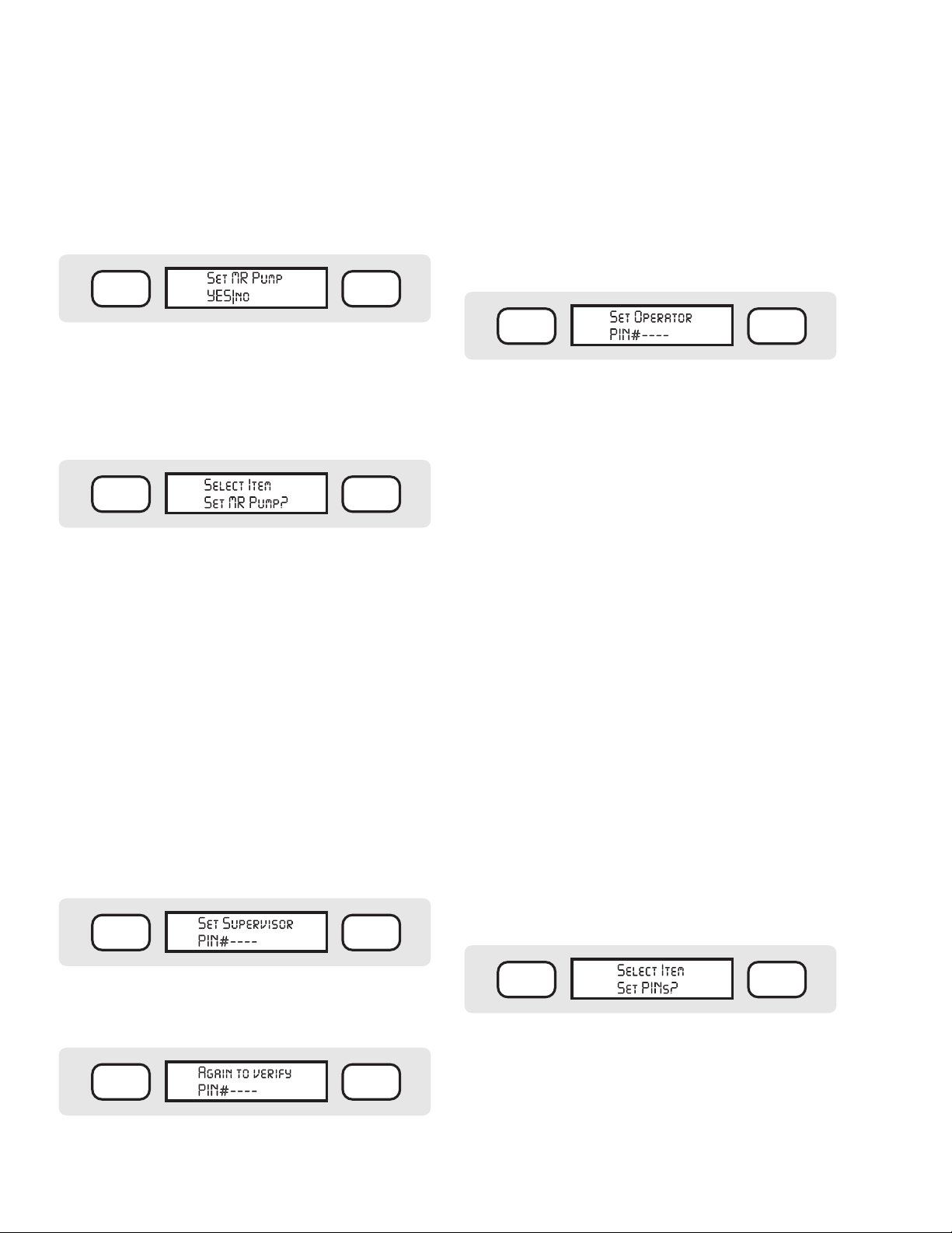
To Set MR Pump: Press ENTER at the “Set MR
Pump?” display. The display will then show:
EXIT OFF
The current selection will be capitalized (default is
YES). The “no” selection will be in lower case. Press
the TOGGLE button to switch between YES and NO.
When it is correct, press ENTER. The display will flash
“SAVED!” and your selection. After a moment, the
display will revert to:
EXIT OFF
You may now press the OPTIONS, BACK, or NEXT
buttons to view more options, or you may press EXIT
to leave the Edit Settings mode.
Set PINS
The IDS controller has 2 levels of optional password
protection:
• The Supervisor level can perform all programming
functions.
• The Operator level can perform basic functions
(START and STOP commands) which do not affect
the automatic programs and their options.
Each level of access can be protected by a 4-digit Personal Identification Number (PIN).
To Set PINs: Press ENTER at the “Set PINs?” display.
The display will then show:
EXIT OFF
Type exactly the same PIN number again and press
ENTER. The display will show “SAVED!”.
If you fail to enter the same number the second time, the
display will show ERROR! You will then need to reenter
the PIN and enter the confirmation a second time.
Once the PIN has been entered correctly, the display
will show:
Repeat the sequence above to enter an Operator’s PIN
number. You are not required to enter a second level
of password protection. If you do not want an Operator level, simply press ENTER at this display without
entering anything.
If the second (verification) entry of either Supervisor or
Operator level PINs is in an error, no PIN has been created.
EXIT OFF
You may change the passwords at any time, but you
must first log on to the controller with the existing
Supervisor-level PIN. If you forget your PIN, it is still
possible to clear the password settings. Contact your
distributor or Hunter Technical Services for help to clear
the password settings.
When you press the EXIT button at any time on the
keypad, it will exit the function you are in and return to
the next-highest level in the controller. After you exit all
the way back to the normal time/ date display, and press
EXIT again, the display will show “ LOGGED OFF”.
This means that a valid PIN must be entered to log back
on before any programming or operations take place (if
PINs are enabled). If you do not log off when finished,
the controller will log off automatically after 3 minutes
of no activity.
When the PIN settings are complete, press ENTER.
The display will flash “SAVED!” and your selection.
After a moment, the display will revert to:
Type any 4 digits (there must be exactly four, from 0001
to 9999) which you will be able to remember, and press
ENTER. The display will show:
EXIT OFF
10
You may now press the OPTIONS, BACK, or NEXT
buttons to view more options, or you may press EXIT
to leave the Edit Settings mode.
EXIT OFF
Page 15

WRITING A FIELD CONTROLLER PROGRAM.............
Press the PROGRAM SELECT button. The display
will show:
EXIT OFF
This indicates that you are in Program # 1, with 0 out
of 64 total Programs in use. The numbers may vary if
there are already programs in the controller’s memory.
There may already be a program name in place of the
dashes. You can edit any Program at any time. For now,
we will work on Program 1 as the controller came “out
of the box.”
Naming a Program
Press the OPTIONS button. The display will show
“ Edit Prg Name?”
Press ENTER. The bottom line of the display will show
“ Alpha entry mode”, and the cursor will be flashing on
the first space.
Use the buttons on the keypad to type in a name for the
Program. You may mix letters and numbers to create
accurate names for each Program (up to 10 total characters long).
Typing Instructions
Each number button also has a series of letters of the
alphabet assigned to it. While the display says “ Alpha
entry mode” the buttons will type letters only. Press
the button rapidly to display the letter you want. If you
release the button for more than about 1 second, the
letter will be selected and the cursor will advance to the
next position.
To create a dash instead of a character, press the NEXT
button to skip over a space and resume typing.
To delete a character and leave the space blank, press
the “1” (one) or “0” (zero) buttons once when in the
Alpha entry mode. They do not have letter assignments
and will create a blank space.
You can also create special symbols with the “1” (one)
or “0” (zero) buttons when in the Alpha entry mode.
With the first button press, they create a blank space.
If you continue to press them rapidly, they will cycle
through the following symbols:
To type numbers, press the TOGGLE button. The
bottom line of the display will show “Num entry
mode”. Now the buttons will type the number on the
button, instead of the letters. To delete a number and
leave a space, TOGGLE back to Alpha entry mode
and use the “1” or “0”, then TOGGLE back to Num
entry mode to continue typing numbers.
When the name in the display is correct, press ENTER.
The display will show “SAVED!” for a moment, then
return to:
EXIT OFF
Where ## is the number of the program, and xxxxxxxxxx
is the new Program name you have entered.
To type the word “TURF”, for example, press the “T”
button (#8) once, and wait for a second. You may hear a
faint beep, and the cursor will advance to the next space.
Press the #8 button twice, rapidly, to display the second
letter “U”. Wait for a second, and the cursor will
advance to the next position. Press the 7 button to type
an “R”. Wait for the cursor to advance, and then press
the #3 button three times in a row to type “F”. The display should now read “TURF”.
If you make a mistake, you can use the BACK and
NEXT buttons to position the cursor on any existing
space, and type a new character. To erase an entire
Program Name, press CLEAR. Be careful, because
CLEAR erases the entire name, not just the space at
the cursor.
Press the EXIT button to leave the Edit Prg Name
programming. The display will return to the Program
Select level, and will show the new name of
the Program.
Assigning a Schedule to a Field Controller Program
The Schedule for a Program determines the days on
which the Program will run. There are two types of
Schedules: Daily or Day of Week.
Daily: Uses the controller calendar to determine the
watering schedule (see Set Schedule Length on page
12). TOGGLE each day, Ye s or No.
11
Page 16

WRITING A FIELD CONTROLLER PROGRAM (CONT.)....
Day of Week: Uses the days of the week (Monday, Tuesday, etc.) to determine the watering schedule. TOGGLE
each day from Capital (water) to lower case (no water).
Press the PROGRAM SELECT button repeatedly
until the name or number of the Program you want
appears in the display. Once you have pressed PRO-
GRAM SELECT, you can also use the BACK and
NEXT buttons to go backward or forward through the
available Programs.
EXIT OFF
IDS
PROGRAM
SELECT
PRESETS
MANUAL
START
NEXTBACK
When the Program you want appears in the display,
press the SCHEDULE button. If the Program has no
Schedule assigned yet, the display will show:
SCHEDULE
STATIONS OPTIONS
123
abc def
456
ghi jkl mno
789
pqrs tuv
CLEAR0TOGGLE
wxyz
ENTER
Day 1-7 shows the number of days in the controller
calendar (as set in the Edit FC Settings selections). If
the calendar is longer than 7 days, the remaining days
will be shown on other “pages” when you finish setting
up the first seven days.
The “Y”s show Yes for each of the days (default setting
is all days to Yes, regardless of how many days are in
the controller calendar). A “Y” means the Program will
run on that day; an “n” means it will not.
To set the days for Yes or no, press the TOGGLE
button. TOGGLE will change the setting for the day
from “Y” to “n”. When the day is set correctly, use
the NEXT key to advance to the next day, and press
TOGGLE again to set up the day. Continue through all
the days of the calendar. If there are more than 7 days,
when you press NEXT after the 7th day is set, the display will show the next “page” of days (Days 8-14).
Do not press ENTER until all the days are set correctly. If you accidentally press ENTER before you are
finished, the display will show “ Enter to Save”. Press
EXIT instead, then press the SCHEDULE button again
to re-enter the scheduling mode.
EXIT OFF
You may press SCHEDULE again to see the Day of
Week option (you can also use TOGGLE, or BACK and
NEXT, to move between the options).
Note: If the Program already has a Schedule assigned,
the SCHEDULE button will immediately show the
existing Schedule. If you want to change to the other
type of Schedule, press the OPTIONS button, and
TOGGLE between the selections as described above.
When the display shows the option you want to use,
press ENTER.
If you select Daily, the display will show something like:
EXIT OFF
The cursor will be flashing under the “Y” corresponding
to the current day.
Prg## will show the Program number selected.
After you have set up the entire Daily Schedule for
the Program, press ENTER. The display will show
“Enter to Save”. Press ENTER again. The display
will briefly show “SAVED!”, and then will return to the
Program Name.
Example: A controller has a 14-day schedule. You want
to set up a Program to irrigate Monday and Thursday
of the first week, and Tuesday and Friday of the second
week. Monday is the first day (“ Day 1”) of the Schedule.
Use the NEXT button and the TOGGLE to create:
EXIT OFF
After the 7th day, press NEXT again, and the display
will advance to Days 8 through 14.
Continue to press NEXT and use TOGGLE to configure the second week:
EXIT OFF
Today= # will display what today’s number is, in the
controller calendar, as in Day 2 of a 14- day schedule.
12
After you have set up the entire Daily Schedule for the
Program, press ENTER. The display will show “Enter
Page 17

to Save”. Press ENTER again. The display will briefly
show “SAVED!”, and then will return to the Program
Name.
To Change a Schedule Which has Already Been Set:
Press the PROGRAM SELECT button until the Pro-
gram you want to change appears in the display.
If you select Day of Week, the display will show some-
thing like:
EXIT OFF
The Program number for the selected Program will be
displayed. DOW = will show which day of the week
today is. The S•M•T•W•T•F•S display represents each
day of the week. The cursor will be under the day of
the week that the controller thinks it is (in the example
above, Tuesday).
Capital letter days are watered. Lower-case lettered days
are non-water days.
Press the TOGGLE button to change the capital “T” (or
any other letter) to a lower-case “t”. Press TOGGLE
again, and the day will change back to a capital “T”.
Press the NEXT (or BACK) button to move to a different day. Create capital letters for each day you want to
water, and lower-case letters for each day you want
to skip.
When the whole week is configured correctly, press
ENTER. The display will briefly show “SAVED!”, and
then will return to the Schedule days you have created.
Example: You want the Program to water all weekdays,
but not weekends. In DOW mode, use the TOGGLE
and NEXT buttons to create:
EXIT OFF
This shows that Sunday and Saturday will not be water
days, but that the rest of the days will irrigate.
Press the SCHEDULE button. The display will show
the type of Schedule currently set up for the Program.
Press the OPTIONS button. The display will show:
EXIT OFF
Type of schedule
You may then press SCHEDULE, or use the BACK
and NEXT buttons, to cycle through the choices available. When the display shows the type of Schedule you
want, press ENTER. Complete the steps for the Schedule types shown above to finish the new schedule.
Assigning a Start Time to a Field Controller Program
The Start Time for a Program determines the time of day
at which the Program will run.
Press the PROGRAM SELECT button repeatedly
until the name or number of the Program you want
appears in the display. Once you have pressed PRO-
GRAM SELECT, you can also use the BACK and
NEXT buttons to go backward or forward through the
available Programs.
EXIT OFF
IDS
PROGRAM
SELECT
PRESETS
MANUAL
START
NEXTBACK
SCHEDULE
STATIONS OPTIONS
123
abc def
456
ghi jkl mno
789
pqrs tuv
CLEAR0TOGGLE
wxyz
ENTER
Press EXIT to leave the Schedule editing mode. The
display will show:
EXIT OFF
You must press the ENTER button with YES capitalized to save the new Program Schedule. If you want to
discard it, press the TOGGLE button to capitalize NO
and press ENTER, and the Schedule will not be saved.
When the Program you want appears in the display,
press the START button. The display will show:
EXIT OFF
You can actually perform two different functions from
here.
13
Page 18

WRITING A FIELD CONTROLLER PROGRAM (CONT.)....
If you press START again, the program will begin run-
ning immediately (so, be careful!). This is the Semiautomatic Start feature.
If you press ENTER, the display will show:
EXIT OFF
The “Prg01” will indicate the Program number you
selected. “XXXXXXXXXX” will be the name of the
Program, if applicable. “Start =” will show the actual
Start Time of day, or OFF if no Start Time has been
programmed yet.
To enter or change a Start Time, simply begin typing
with the number buttons on the keypad. The number will
appear in the display in place of the word OFF or the
previous Start Time. It is not necessary to enter leading
zeroes. For example, to create a Start Time of 9:30 PM,
type 9 3 0 and press ENTER.
The display will then add AM|pm to the time. Press the
TOGGLE button to change between AM and PM. When
the time is correct, press ENTER. The display will
show “ Enter to Save”. Press ENTER again, and the
display will show SAVED! and the time you have set for
the Start Time.
The controller will automatically start the Program at
the time shown (you can also enter multiple cycles, and
cycle delays, for the Program; this is described in detail
in the Programming Advanced Options section).
of the X, you can program a 1, 2, 3, or 4 to tell it which
station you want to program, or activate. The color-code
for each of the four stations is printed on the side of the
decoder (1=black, 2=yellow, 3=green, 4=white). A single
ID4, therefore, can represent up to four stations in the
IDS controller.
A run time is the length of time for which the station will be activated, or in other words, how long the
sprinklers it controls will run. Each station run time is
separately programmed. Run times may be programmed
in 1- minute increments, from 1 minute to 18 hours, 12
minutes, in hh:mm format.
A station may appear in more than one Program, and it
may appear in the same Program more than once. Stations may run in any order, and are not required to run
sequentially in numerical order.
An Event refers to the order in which the station will
run. You can run any station in any order, by setting its
Event number. Events always occur in sequence, from
#1 to the last event. You can assign any station # to any
Event #. Each Program may have up to 30 Events.
To Program Individual Stations
Press the PROGRAM SELECT button repeatedly
until the name or number of the Program you want
appears in the display. Once you have pressed PRO-
GRAM SELECT, you can also use the BACK and
NEXT buttons to go backward or forward through the
available Programs.
EXIT OFF
Programming Stations: Run Times, Events, and Blocks
A Station is a single electrical output to a solenoid on a
valve, originating from the field controller. In decoder
systems, each station is a uniquely-numbered decoder
output along the two-wire path. The IDS controller
may have up to 103 stations, plus a separate Pump
decoder output.
The ID1 single- station decoder may be connected to up
to 2 solenoids. However, they will both start at once,
and are treated as a single station for programming
purposes. The unique 8-digit Serial Number printed on
the actual decoder is associated with a station number
in the IDS controller.
The ID4 four- station decoder has 4 separate outputs,
and each one is a true, independent station. The ID4
has a unique 7-digit number, followed by an X. In place
14
IDS
PROGRAM
SELECT
PRESETS
MANUAL
START
NEXTBACK
When the Program you want appears in the display,
press the STATIONS button. The display will show:
EXIT OFF
Or actual numbers or 9:30 PM or 9:30 PM – 10:45 PM
This initial display shows the total time for the Program
selected, and the start and end times for the Program. If
SCHEDULE
STATIONS OPTIONS
123
abc def
456
ghi jkl mno
789
pqrs tuv
CLEAR0TOGGLE
wxyz
ENTER
Page 19

it is a new Program, or the Start Time has been cleared,
the second line will show “No Start Time”. If there is
already a Start Time, that time will be shown. If Station
Run Times already exist, the Start and the end time for
the Program will be shown.
For example, if a Program contains 32 minutes of
irrigation, and is set to begin at 8:00
PM, the display
would show:
You can continue in this manner until all the stations
you want in the selected Program are programmed.
Remember that you can enter any stations, in any order.
Example:
EXIT OFF
Total is 0:32
8:00pm – 8:32pm
If Continuous cycles have been selected for a Program,
the display will differ, depending on your settings (see
XXXCycles).
Press the STATIONS button again. The display will
show (example):
EXIT OFF
...or, if the station has never been programmed before,
as at initial installation, it will show:
EXIT OFF
This will show the station information for the first
“Event” in the Program. The Program selected is shown
in the upper left. The Event number is in the upper right.
The station or block is in the lower left. The actual Run
Time for the station is in the lower right.
To program a new Station Run Time, verify that the
cursor is under the Station number. (At the station
number position, you can also press the TOGGLE
button to change from a Station to a Block. If you select
a Block, the number will refer to a Block number, not
an individual station. See Blocks on page 16 for more
information.)
Type the number of the station or Block you want. Press
ENTER.
The cursor will advance to the Run Time field. Type the
Run Time you want for that station or Block (up to 18
hours and 12 minutes), and press ENTER.
Event# Station# Run Time
(hours:minutes)
1 3 0:10
2 5 0:08
3 7 0:12
4 8 0:04
5 6 0:20
6 4 0:11
7 2 0:08
8 10 0:10
9 1 0:12
10 9 0:05
Event #1 will begin at the assigned Start Time for the
Program (9:30
PM) and run for 10 minutes. Event #2 will
follow immediately after it (Station #5 for 8 minutes),
then Event #3, and so forth. The total Run Time for the
Program is 100 minutes, so the end time shown will be
11:10 PM.
You may find it easiest to simply run the stations in
numerical order (where Event #1 = Station #1, Event #2
= Station #2, etc.), but IDS has the flexibility to run stations in any order.
When you have finished entering the Run Times for all
the stations you want in the Program, press the EXIT
button. The display will show:
EXIT OFF
The “YES” will be capitalized. To continue saving
the changes, press ENTER. The display will flash
“SAVED!” and your selection. After a moment, the
display will revert to the Program Name.
You must now press the STATIONS button to
advance to the next event, and program another station
(or Block).
If you just want to exit and not save the changes, press
TOGGLE to change “no” to “NO” and press ENTER
15
Page 20

WRITING A FIELD CONTROLLER PROGRAM (CONT.)....
The changes will be discarded, and the Run Times will
be left the way they were.
Blocks
A Block is a group of more than one station (up to 8
per block) which will activate all at once, which are
given a single run time, and which may be included in
a sequence just like a single station. A Block counts
as a single Event regardless of how many stations are
assigned to it. It is technically possible to create a Block
of only 1 station, but this defeats the purpose of
this feature.
When multiple stations are activated in a Block, they are
actually staggered at 1-second intervals to prevent the
simultaneous electrical inrush draw of all the solenoids.
Blocks may be used to help you in several ways. They
allow you to program and adjust large numbers of
sprinklers with fewer keystrokes, since many sprinklers
of similar types will have identical run times.
Blocks can also irrigate more efficiently than single
stations, because the “cloud” of spray from multiple
sprinklers running simultaneously cools hot surfaces,
and reduces the evaporation of individual sprinkler
applications.
Block #2
Block #1
If you group similar sprinklers with similar flow capacities into Blocks, you can have a fairly constant level of
flow, even for a large number of sequencing Events.
By permitting Blocks to sequence ( simultaneous groups
of 4 stations on an ornamental slope, for example),
large areas can be irrigated with fewer Programs and
less complicated sequences.
Block #3
Blocks may also be included in Preset programs, and
can be used to “syringe” overheated turf areas more
efficiently and quickly. One or two Blocks can wet an
entire turf area in a single run time or two.
16
Page 21

Creating Blocks: Blocks are created, edited, or deleted
at the Field Controller Option level. Each Field Controller
may have up to 64 Blocks, which are always the same,
regardless of which Programs they are included in.
With no programs selected, from the basic time date
display on the controller, press the OPTIONS button
approximately 4 times until the display shows:
EXIT OFF
Press ENTER. The display will show:
EXIT OFF
To create a Block, press ENTER. The display will show:
EXIT OFF
Press ENTER. The display will show:
EXIT OFF
Press OPTIONS again. The display will show:
EXIT OFF
Press OPTIONS again. The display will show:
EXIT OFF
To edit an existing Block, press the OPTIONS button
until Edit a Block? is shown, and press ENTER. The
display will show:
EXIT OFF
Type the station number for the first station in the block,
and press ENTER. The display will show:
EXIT OFF
Type the next station number and press ENTER, and so
on, up to 8 stations. When the block is complete, press
ENTER again. The display will show “SAVED!” and
will return to the Create A Block? message. You may
then create another Block, or press EXIT to leave the
Block mode.
Note that run times and Events are not assigned to
Blocks here. This only creates the Blocks, by assigning
stations to them. The actual run times are assigned to
the Blocks in the individual Programs, under the Stations button functions.
Editing and Removing Blocks: Once Blocks are created,
they may be edited, or removed altogether. With no
Programs selected, from the basic time date display on
the controller, press the OPTIONS button 4 times until
the display shows:
EXIT OFF
This list will always show all of the currently
existing Blocks
In this example, the controller already has more than 5
Blocks created, and the arrow symbol is prompting you
to press the NEXT button to view more Block numbers.
Type the number of the Block you want to edit (for
example, “3”) and press ENTER. The display will then
show the station numbers included in that block, and
will also show “---” for any unoccupied spaces in the
Block. You may now add more stations, or remove existing stations from the Block.
To remove a station from an existing Block, press the
NEXT button to advance to the station, and press
CLEAR or “0” (zero). Press ENTER.
To add a new station to an existing Block, press
the NEXT button to advance to the next blank spot
(---), type in the number of the new station, and press
ENTER. It is not necessary to enter leading zeroes. For
example, to add station 7 to a Block, simply type “7” at
a blank spot and press ENTER. You may then advance
to the next blank spot and enter, change, or remove
more stations in the Block.
You may also replace one station in an existing Block
with another. Press NEXT to advance to the station you
17
Page 22

WRITING A FIELD CONTROLLER PROGRAM (CONT.)....
want to replace, simply type the new station number
right over it, and press ENTER. This will remove the
original station, and add the new station in its place.
When the Block editing is complete, press ENTER
again. The display will ask:
EXIT OFF
If you want to save the Block edits, press ENTER (with
the YES capitalized). The display will show:
EXIT OFF
The display will then revert to the Edit a Block? option
level.
To remove an existing Block, press the ENTER button
when Remove a Block? is shown. The display will
show:
specific event is to continue pressing the STATIONS
button until the display shows the Event you want to
edit. When the specific Event is shown in the display,
press the OPTIONS button. The OPTIONS button will
cycle through the Station-level options, which are as
follows:
EXIT OFF
EXIT OFF
EXIT OFF
EXIT OFF
EXIT OFF
In this example, the controller already has more than 5
Blocks created, and the arrow symbol is prompting you
to press the NEXT button to view more Block numbers.
Type the number of the Block you want to remove (for
example, “2”) and press ENTER. The display will show
REMOVED and the block will be permanently deleted.
Station Options (Changing Events)
As noted above, stations or Blocks can run in any order.
You do this by editing Events. There are several options
available to edit Events.
Remember: The Event refers to the order in which the
station will run. You can run any station in any order,
by setting its Event number. Events always occur in
sequence, from #1 to the last event. You can assign any
station # to any Event #.
Events are part of a specific Program, so the first step is
to press PROGRAM SELECT on the keypad until the
Program you want to edit appears in the display.
Then press the STATIONS button once. The display
will show the current total run time of the Program.
The easiest way to access most of the functions for a
Delete an Event: To delete the data in an existing Event,
press ENTER when the displays shows Delete an
Event? The display will then ask, Delete data in Event
#x? (where x = the number of the Event you were on).
Press ENTER. The display will show OK! and the Event
will be deleted.
Note that you don’t really delete Events, but the data in
the Events. In effect, the whole sequence of stations or
Blocks will move backward one Event, to fill the slot that
was just deleted.
Example: If the existing Events were as follows:
Event # 1 2 3 4
Station # 5 6 7 8
...and you then delete the data in Event #2, the new
Event list would look like:
Event # 1 2 3
Station # 5 7 8
Since there are only 3 remaining stations, the last Event
is now #3.
Cluster Events?: “ Cluster” is a mass-programming
function for large groups of similar stations. When you
first program a controller, you may want to set up all the
18
Page 23

same types of sprinklers with the same run time, see
what happens, and adjust individual stations from there.
“ Cluster” lets you assign a single run time to large numbers of sequentially numbered stations, with a minimum
number of keystrokes.
Press ENTER to cluster the stations and run times you
entered. The display will briefly show “OK!” and then
return to the Cluster Event? Option. Press EXIT if you
are done programming stations, and the display will
return to the Stations display.
To do this, the Cluster command will assign a consecutive sequence of station numbers to a consecutive
sequence of Event numbers, with a single run time
for all.
To cluster Events, press STATIONS to get to the sta-
tion where you want to begin a Cluster (often station 1),
and press OPTIONS until the display shows Cluster
Events? Press ENTER. The display will show:
EXIT OFF
Where x = the number of the Event you were on.
Type the number of the Event you want, or just press
ENTER to accept the choice offered. The display
will show:
EXIT OFF
Since 30 is the maximum number of Events in a Program, the controller will always offer to cluster up to
Event #30. You may type any existing Event number
higher than the starting Event to cluster to, and press
ENTER. The display will then show:
The controller will then assign the run time to every station in the cluster, beginning with the lowest numbered
station and ending at the last one in the cluster.
When you have finished entering the Run Times for all
the stations you want in the Program, press the EXIT
button. The display will show:
EXIT OFF
If you want to save the new Run Times, press ENTER
(with the YES capitalized). The display will show:
EXIT OFF
The display will then revert to the Program Name display.
Example:
EXIT OFF
EXIT OFF
EXIT OFF
You may start at any station number. Simply type the
number of the station at which you want to begin, and
press ENTER. The display will then show:
EXIT OFF
Type the run time you want all the clustered stations to
use. The display will then show:
EXIT OFF
EXIT OFF
EXIT OFF
The controller will create 12 Events, from 001 to 012.
Stations 5 through 16 will run in sequence, for 10 minutes apiece.
Move an Event: You can also move the data from one
event to another location in a Program, if you want a
19
Page 24

WRITING A FIELD CONTROLLER PROGRAM (CONT.)....
Figure 1
specific station to keep its run time, but activate in a
different order.
In Figure 1, you might want to move station #6 (Event
#2) to activate after station #14 (Event #10).
To move an Event, press STATIONS until the Event you
want to move appears in the display. Press OPTIONS
until “ Move an Event?” appears in the display. Press
ENTER. The display will show:
EXIT OFF
Press ENTER (you may also type in a different Event
number). The display will show:
EXIT OFF
Type the Event # you want to move the data to (#10,
in this example), and press ENTER. The display will
briefly show OK, and revert to the Move Event? display.
within the 12 numbers. You cannot have an “empty”
Event in the middle of a sequence. Trying to move to
Event #13 would cause the ERROR! message.
Insert an Event: You can insert a new Event in between
existing Events. In the example above, you might want
to insert station #4, with a run time of 7 minutes, in
between stations #8 and #9 (Events 3 and 4).
Press the STATIONS button to advance to the Event
where you want to insert an Event (Event #4, in the
example). Press the OPTIONS button until the display
shows Insert an Event? Press ENTER. The display
will show:
EXIT OFF
Press ENTER. The display will briefly show OK! and
will then revert to the Insert Event? option. You have
now created a blank Event at Event #4. The stations and
Event that were at #4 are now at Event #5, and the rest
of the sequence has been pushed back, to make room
for the new Event.
As you can see in Figure 2, the Event data has been
moved. Note that the other Events move forward to fill
the slot formerly occupied by station #6. No data was
lost. Only the order in which the stations will activate
has changed.
Note: If you try to move an Event # that does not exist,
or try to move an Event to an impossible #, the display
will briefly show ERROR! and return you to the option.
If you only have 12 Events, you can only move an Event
Figure 2
Figure 3
20
You may now press STATIONS until you arrive at the
blank Event, and fill it in (in Figure 3, Station #4 with
a run time of 7 minutes). The new Event data has been
inserted. Note that the later Events move back to make
room for the new Event. You have only inserted a new
Event into the Program sequence.
Page 25

PROGRAM ADVANCED OPTIONS..................................
The previous sections covered the basic concepts of
writing a Program from the IDS controller keypad:
Program, Schedule, Start Time, and Station run times,
as well as Blocks and Events.
The Program Options provide additional power and flexibility at the individual Program level.
They are:
Edit Program Name
Set Program % Scale
Cycles
Cycle Delay
Skip Days
Pump
Edit Program Name
Covered in detail in the section “ Naming a Program” on
page 11.
Set Program % Scale
This is one of the most convenient and frequently
used options in the controller. In the Field Controller
Settings section, we described the “Main % Scale” (see
Set Main % Scale on page 21), which affects the entire
Field Controller.
resulting from these calculations are always rounded to
the nearest minute.
Base Run Time .......................................... 10 min.
Multiplied by ............................................. x
Program Scale........................................... 150%
Result ....................................................... 15 min.
Multiplied by ............................................. x
Main Scale ................................................ 50%
Result (rounded up to 8)............................ 7.5 min.
To Set Program % Scale: Press PROGRAM SELECT
until the name of the Program you want to adjust
appears. Press OPTIONS twice, until Set Prg Scale?
appears. Press ENTER. The display will show:
EXIT OFF
Type the percentage scale you want with the number
buttons on the keypad, and press ENTER. The display will briefly show “SAVED!” and the new % Scale
amount. After a moment, the display will revert to:
EXIT OFF
“Program % Scale” allows you to reduce or increase all
of the Run Times in a single Program by the selected
percentage (from 1 to 250%, in 1% increments). This
enables you to quickly adjust the amount of irrigation
for weather or other conditions without changing the
basic program. At 50%, each Run Time will only run half
as long, and at 150%, each Run Time will run one-andhalf times as long.
When this Option is selected at the Program level, it
permits you to tailor certain plant areas for local conditions. If you only want to adjust the turf irrigation, for
example, without affecting the shrub irrigation, you
would % Scale just those Programs with turf sprinklers
in them.
Important: The effects of % Scale at the Main (controller) and Program levels are cumulative. The controller
looks first at the Program Scale, and then at the Main
scale, to calculate the scaled run time.
In other words, if the original (or base) run time of a
station is 10 minutes, and the Program % Scale is set to
150%, the scaled run time would be 15 minutes. If the
controller Main Scale is then set to 50%, the net total
run time for the station would be 8 minutes. Fractions
You may now press the OPTIONS, BACK, or NEXT
buttons to view more options, or you may press EXIT
to leave the Program Options mode.
Note that, whenever a Program is scaled up or down
(to any value other than 100%) and saved, a “+” or “-”
sign appears as a reminder in the upper left corner of
the display before the Program name, when pressing
PROGRAM SELECT to view Programs.
The “+” or “-” signs will also appear next to the Total
when STATIONS is first pressed in a scaled Program.
If you continue to press STATIONS to view individual
Station run times, the “+” or “-” sign will appear next
to the Event number, and the actual scaled run times
are shown in the run time area of the display. This is a
reminder that you are viewing a scaled run time, and not
the base run time.
Cycles
The Cycles option specifies the number of times a Program will run. The default value is 1, so that once you
have created a Program, it will run the entire sequence
of stations once per scheduled day.
21
Page 26

PROGRAM ADVANCED OPTIONS (CONTINUED)..................
You may specify from 0 to 15 Cycles, per Program,
however. Be careful – entering “0” Cycles specifies
Continuous cycles, for special applications.
Multiple cycles are useful when your plants require
more water than the ground is capable of absorbing in
a single application (such as very dense or compacted
soil, or sloped areas), or when you wish to keep an area
wet with many short applications (germinating seed,
grow-in, etc.). You can also specify a Delay between
each cycle at the next option setting.
Continuous cycles (the “0” option) mean that the program will cycle infinitely, or until an End Time. This feature is useful when you are germinating new seed, for
example. You can specify some very short run times to
keep the seed wet, and Delay Times between the cycles
as needed. Once the Program is started, it will run this
cycle forever, or until a human shuts it off.
Continuous (0) Cycles is only possible for FCP programs, and is not an option for Presets. Presets may
have up to 15 Cycles, however.
You can also run continuous cycles until an automatic
End Time (see XXXEnd Time). You can run the continuous program as described above until (for example)
9:00 PM. This way you are not required to figure out
how many cycles and delays are required to keep the
seed wet until 9 o’clock. You simply need to set up the
program, and tell it when to end. The continuous cycle
will stop at the End Time (regardless of what station it
happens to be on).
To Set the Number of Cycles: Press PROGRAM
SELECT until the name of the Program you want to
adjust appears. Press OPTIONS until Set Cycles?
appears. Press ENTER. The display will show:
EXIT OFF
Type the number of cycles you want (0 to 15) with the
number buttons on the keypad, and press ENTER.
If you have entered a number from 1 to 15 (see below
for the “0” Cycles option), the display will briefly show
“SAVED!” and the new number of cycles. After a
moment, the display will revert to Set Cycles? You
may now press the OPTIONS, BACK, or NEXT but-
tons to view more options, or you may press EXIT to
leave the Program Options mode.
Note that the next time you press the STATIONS button
while in this Program, the Total run time will be updated
to reflect the number of cycles (and Cycle Delays, if set)
of the Program.
If you have entered “0” Cycles, the display will ask
“CONTINUOUS? YES|no” to confirm that you want
continuous irrigation. If you want Continuous cycles,
press ENTER. To exit the Cycles option without setting
Continuous, use the TOGGLE button to capitalize NO
and press ENTER. You will be returned to the Set
Cycles? Display.
When Continuous cycles are selected, the program total
is displayed differently when you first press the Stations
key, after selecting a Program.
If your Program has continuous cycles with a set End
Time (see XXX), the display will show the total time
from beginning to end, including cycle delays. For
example, a program running continuously from 8:00 PM
to 6:00 AM would show:
Total is 10:00
8:00pm – 6:00am
If your Program has continuous cycles with no set End
Time, the display will show the total for a single cycle,
and the start time followed by NO END. This will remind
you (or a less experienced assistant) that the Program
is set to irrigate continuously.
If the program contained 32 minutes worth of irrigation,
had a Start Time of 8:00 PM, and was set to continuous cycles, with no End Time, the Stations total display
would show:
Total is 0:32
8:00pm – NO END
Note that if Cycle Delays (next section) have been set,
they will apply in between Continuous cycles. However,
the Cycle Delay is not included in the total time shown
for the Program when it is set to Continuous cycles, if
there is no End Time.
Cycle Delay
This is the amount of time the Program will wait
between multiple (or continuous) cycles, before starting
again. There is only 1 cycle delay factor per Program,
which will occur between all cycles (including continuous cycles). If there is only 1 cycle, Cycle Delay will not
have any effect at all.
To Set the Cycle Delay: Press PROGRAM SELECT
until the name of the Program you want to adjust
appears. Press OPTIONS until Set Cycle Delay?
22
Page 27

appears. Press ENTER. The display will show:
EXIT OFF
Or the display will show: Delay = ##:## if a delay has
already been programmed.
Continuous Cycles with End Time
Program 1: WEST LAWN
Cycles: 0 (continuous)
Cycle Delay: 2 Hours
Start Time: 9:00 PM
End Time: 7:00 AM
Total Run Time: 10 hours
Type the length of the cycle delay you want in hours:
minutes format with the number buttons on the keypad.
(You can also clear out an existing delay by typing “0”
or pressing CLEAR). Press ENTER. The display
will show:
EXIT OFF
Press ENTER to save the new delay. The display will
briefly show SAVED! and the length of the cycle delay
you have entered. After a moment, the display will
revert to Set Cycle Delay? You may now press the
OPTIONS, BACK, or NEXT buttons to view more
options, or you may press EXIT to leave the Program
Options mode.
Note that the next time you press the STATIONS button
while in this Program, the Total run time will be updated
to reflect the number of cycles and the cycle delays of
the Program.
Example:
Single Cycle
Program 1: WEST LAWN
Cycles: 1
Total Run Time: 1 hour
Skip Days
Skip Days suspend a Program for a specified number
of days, after which the Program will resume operating
normally. You can use Skip Days when a weather front
is approaching and you know you won’t need to irrigate
for 2 or 3 days, or when you have repair work going on
and you do not want any irrigation until the repairs are
completed, or any other time you want to temporarily
halt a Program without having to remember to turn it
back on.
Skip Days count consecutive days, and do not take
into account the scheduled days “on” for the particular
Program. Skip Days will suspend the Program for the
specified number of calendar days. If the resume day
was a “no water” day for the Program’s normal schedule, it will still be a “no water” day when the Skip Days
times out.
Note that if you set Skip Days for a Program while it is
already running (after its automatic Start Time), the Program will finish irrigating normally, and the next day will
count as the first Skip Day.
To Set Skip Days for a Program: Press PROGRAM
SELECT until the name of the Program you want to
suspend appears. Press OPTIONS until Set Skip
Days? appears. Press ENTER. The display will show:
Multiple Cycles
Program 1: WEST LAWN
Cycles: 2
Total Run Time: 2 hours
Cycles with Delay
Program 1: WEST LAWN
Cycles: 2
Cycle Delay: 2 Hours
Total Run Time: 4 Hours
Continuous Cycles
Program 1: WEST LAWN
Cycles: 0 (continuous)
Cycle Delay: 2 Hours
Total Run Time: NO END
EXIT OFF
Type the number of days you want the Program to
Skip, and press ENTER. The display will briefly
show SAVED! and the number of Skip Days you have
entered. After a moment, the display will revert to
Set Skip Days? You may now press the OPTIONS,
BACK, or NEXT buttons to view more options, or you
may press EXIT to leave the Program Options mode.
If you return tomorrow (after the next Time of Day
change) and view the Skip Days for the Program,
the Skip Days will be updated to show the remaining
number of days to be skipped. For example, if you enter
3 Skip Days today, tomorrow the display will show “2”,
and the day after it will show “1”. The display will count
23
Page 28

PROGRAM ADVANCED OPTIONS (CONTINUED)..................
down the days until the Program resumes automatic
operation. The maximum number of Skip Days is 999
days, or approximately 3 years.
Pump
Every IDS controller has a dedicated, programmable
Pump output ( station number “0”). The Pump option
designates whether the specified Program will automatically activate this output. The Pump (or Master Valve)
decoder is programmed like any other decoder, but is
only activated in conjunction with a Program which has
“ Pump” set to Ye s.
The Pump output may activate a pump start relay (such
as Hunter Industries PSR-22) series relays) connected
to a pump, or it may be used to control a master valve
solenoid. The Pump output must never be connected
directly into a high voltage switch (see installation
instructions for further information).
In systems where the pump is activated by the individual controllers, this option is used to provide pump
pressure to the Programs that require it, and to operate without it for any Programs that may not require
it. For example, if your controller operates both rotors
and spray heads connected to city water, you may have
a booster pump to provide additional pressure for the
rotors. In this case you could have the Pump option set
to “Ye s” for the Programs containing the rotors, but
“No” for the Programs containing the spray heads (if
they would be over-pressurized with the booster pump).
Keep in mind that if any Program in the system activates
the pump, it is activated regardless of whether any other
Programs are running with Pump “No” selected.
To Set the Pump: Press PROGRAM SELECT until
the name of the Program you want to set the Pump for
appears. Press OPTIONS until Use Pump? appears.
Press ENTER. The display will show:
EXIT OFF
End Time
Each Program in IDS may have its own optional End
Time. The End Time setting sets an absolute end to any
irrigation for the selected Program. This can be used in
two ways:
An End Time prevents accidental irrigation during
times of day when irrigation must not be permitted,
such as when employees are arriving at a work place in
the morning. If you use the Percent Scale function to
increase watering, it may unwittingly extend watering
outside of the normal “water window” and annoy customers. The End Time will terminate any automatic irrigation at the specified time of day, regardless of where
it is in the irrigation schedule. End Times do not prevent
new irrigation from starting after the End Time. They
only terminate automatic or semi-automatic programs
that are running when the End Time is reached.
An End Time is also the only way to automatically
terminate Continuous cycles. If you want to keep seed
wet during the day, but do not want the irrigation to
continue at night, you could set an End Time of 8:00 PM,
for example. Set up the Program to irrigate continuously
from a 7:00 AM Start Time, for example, and it will cycle
continuously throughout the day but stop automatically
at 8:00 PM.
End Times are by Program. An End Time on one program has no effect on other Programs that may be running. Each Program can have its own End Time, or no
end time at all. Presets do not have, and are not affected
by, End Times.
Note that when IDS displays a total time (the first time
you press Stations, after selecting a Program) it will
always show a start and stop time, based on the Program settings. This is not the same as an End Time,
but is merely calculated from the start time (adding all
the station run times, cycles, and cycle delays) for your
information. End Times are independent of this calculation and will stop any automatic program when the End
Time is reached, regardless of the calculated stop time.
The current selection will be capitalized (default is
YES). The “no” selection will be in lower case. Press
the TOGGLE button to switch between YES and NO.
When it is correct, press ENTER. The display will flash
“SAVED!” and your selection. After a moment, the
display will revert to Use Pump? You may now press
the OPTIONS, BACK, or NEXT buttons to view more
options, or you may press EXIT to leave the Program
Options mode.
24
To Program an End Time: Press PROGRAM SELECT
until the name of the Program you want appears. Press
OPTIONS until Set End Time? appears in the display (you can also press the BACK key after pressing
OPTIONS, since End Time is the last Program-level
Option). Press ENTER. The display will show:
Prg01 XXXXXXXXXX
End= OFF
Page 29

The “Prg01 XXXXXXXXXX” will indicate the Program
number and name you have selected. “End= OFF” will
appear if no End Time has previously been programmed,
The Program will now terminate automatically at the set
End Time. If the program has completed before the End
Time is reached, the End Time will have no effect.
or “End= xx:xxam” may appear if there is already an
End Time.
Note that End Times will also apply if the same Program
is started semi-automatically and is still running when
To enter or change an End Time, simply type the new
the End Time is reached.
time in hh:mm format, and press Enter. It is not necessary to enter leading zeroes. The display will then add
AM|pm to the time display. Press the TOGGLE button
End Time has no effect on Manually started stations
(see next section) or Presets.
to select the correct am/pm setting, and press Enter
again. The display will show “ Enter to Save”. Press
ENTER again, and the display will show “SAVED!”
and the time you have set for the End Time.
MANUAL STARTS ............................................................
You can quickly start one or more stations in the controller with the Manual button. Since more than one
station can be started with this command, this is often
called a Manual Program.
The Manual Program is temporary and is not retained in
memory after the Program has finished running.
You must specify a time for each station to run. If you
enter multiple stations, you may choose whether to run
them sequentially, or simultaneously. You can create a
Manual Program for up to 20 stations (the IDS controller may operate up to 20 decoders simultaneously).
Manual does not usually interrupt Automatic or Semiautomatic FCPs or other Programs which may be
running. Any solenoids or decoders activated by other
Programs must be taken into account when determining how many stations to turn on. In the unlikely event
that the total of Automatic, Semi-automatic, and Manual
events exceeds 20 simultaneous events, the excess
events will be held until some events time out, and may
run later than expected.
EXIT OFF
To Start a Manual Program: Press the MANUAL button
on the keypad. The display will show:
EXIT OFF
Type the number of the station you want to start, and
press ENTER. The cursor will then move to the min-
utes section of the run time section (00:00) of the
display. Type the amount of time you want the station to
run for and press ENTER.
EXIT OFF
You may now enter more stations to start manually, if
you wish. If you only want to start one station, simply
press ENTER again, instead of entering another sta-
tion. If you are starting multiple stations, continue
entering the stations and run times until the Manual
Program is complete, and then press ENTER again.
The display will show:
PROGRAM
SELECT
PRESETS
MANUAL
START
SCHEDULE
NEXTBACK
STATIONS OPTIONS
123
abc def
456
ghi jkl mno
789
pqrs tuv
CLEAR0TOGGLE
wxyz
IDS
ENTER
EXIT OFF
This selection determines whether the Pump output
(decoder station #0) from the controller will also be
activated along with the Manual stations. Press the
TOGGLE button to change YES to NO if you do not
want the Pump active during the Manual Program. When
the Pump setting is correct, press ENTER.
25
Page 30

MANUAL STARTS (CONTINUED) ............................................
If you have only entered one station, the display will
briefly show “OK!” and the station will begin running
for the specified time. If you have entered more than
one station, the display will show:
EXIT OFF
“SEQ” means the stations will run sequentially, in
the order in which they were entered. If you press the
TOGGLE button to capitalize “SIM”, all of the stations
will begin simultaneously.
Use TOGGLE to capitalize the mode you want, and
press ENTER.
Note: Simultaneous starts are actually staggered
at one-second intervals to prevent simultaneous
inrush currents.
When stations begin running sequentially, the display
will show:
running, and “0:nn” is the amount of time left to go on
If you requested the stations to run simultaneously, the
display will show:
currently running, and “0:nn” is the amount of time left
In the Simultaneous mode, the display will sequence
through all the stations currently running and show the
remaining time on each station.
EXIT OFF
Where “xxx” is the number of the station currently
that station.
EXIT OFF
Where “xxx” is the number of one of the stations
to go on the station.
SEMI-AUTOMATIC PROGRAM OPERATION ...............
Any automatic Program can be easily started at any time
from the keypad. This is called “semiautomatic operation” and is useful for irrigating, right now, any area that
is normally handled by an automatic Program. You can
use this to irrigate a fertilized area, or for frost or dew
control, or for any other purpose.
To Semi-Automatically Start a Program
EXIT OFF
IDS
PROGRAM
SELECT
PRESETS
MANUAL
START
NEXTBACK
SCHEDULE
STATIONS OPTIONS
123
abc def
456
ghi jkl mno
789
pqrs tuv
CLEAR0TOGGLE
wxyz
ENTER
Press the START button. The display will show:
EXIT OFF
Press START again. The Program will begin running.
It will irrigate the entire Program, including all Cycles
and Delays.
EXIT OFF
PROGRAM
SELECT
PRESETS
MANUAL
START
NEXTBACK
SCHEDULE
STATIONS OPTIONS
123
abc def
456
ghi jkl mno
789
pqrs tuv
CLEAR0TOGGLE
wxyz
IDS
ENTER
Press PROGRAM SELECT until the Program you
want to start appears in the display.
26
If you semi-automatically run an automatic Program
during the day, it will still run later at its assigned automatic Start Time.
Page 31

PRESETS ...........................................................................
Presets are like automatic Field Controller Programs,
except that they have no Schedule or Start Time,
and are created to provide custom irrigation for a specific purpose.
Presets are activated from the keypad (or an optional
Maintenance Radio) whenever you want to run them.
They can be used to “syringe” overheated turf at mid
day, clear dew or frost from an area, water-in chemical
or organic applications, or any other common task.
Presets work with either individual Stations or Blocks.
Both can exist in the same Preset.
The difference between a Preset and a semiautomatic
start is that a Preset can be written, named, and stored
to provide custom irrigation for a specific purpose. The
automatic Programs may be overkill for cooling hot turf
at midday, for example.
A Preset can be created to trigger two or more Blocks
of sprinklers, each for half of a large turf area, each
with a run time of 3 minutes. This would allow a rapid
cooling of the turf while it is clear of people, without
risking over-watering. The Preset can be named for what
it is (“SYRNG LAWN”, for example) and recalled and
started anytime you want to syringe that area.
Use the buttons on the keypad to type in a name for
the Preset. You may mix letters and numbers to create
accurate names for each Preset (up to 10 total char-
acters long). See Typing Instructions on page 11 for
detailed instructions.
When the name in the display is correct, press ENTER.
The display will show “SAVED!” for a moment, then
return to:
EXIT OFF
Where ## is the number of the program, and xxxxxxxxxx
is the new Preset name you have entered.
Press the EXIT button to leave the “ Edit Prg Name?”
programming.
Most of the Program Options are also available for Pre-
sets. Presets may have multiple Cycles, Delays, and may
be % Scaled. Presets do not have Continuous Cycles or
End Times, however.
You do not create Schedules and Start Times for Pre-
sets. Instead, with the new Preset name in the display,
press STATIONS.
To Create a Preset
EXIT OFF
IDS
PROGRAM
SCHEDULE
SELECT
PRESETS
MANUAL
START
NEXTBACK
Press the PRESET button. The display will show:
EXIT OFF
Press the OPTIONS button. The display will show
“ Edit Prg Name?”
Press ENTER. The bottom line of the display will show
“ Alpha entry mode”, and the cursor will be flashing on
the first space.
STATIONS OPTIONS
123
abc def
456
ghi jkl mno
789
pqrs tuv
CLEAR0TOGGLE
wxyz
ENTER
Refer to Programming Individual Stations on page 14
for detailed instructions on entering stations or Blocks
and their run times. When complete, press EXIT. The
display will show:
EXIT OFF
If you want to save the new Run Times, press ENTER
(with the YES capitalized). The display will show:
EXIT OFF
The display will then revert to the Preset Name display.
27
Page 32

PRESETS (CONTINUED)............................................................
To Start a Preset
EXIT OFF
IDS
PROGRAM
SELECT
PRESETS
MANUAL
START
NEXTBACK
With only the Day and Time in the display, press the
PRESET button until the Preset you want to trigger
appears in the display.
EXIT OFF
PROGRAM
SELECT
PRESETS
MANUAL
START
NEXTBACK
SCHEDULE
SCHEDULE
STATIONS OPTIONS
123
abc def
456
ghi jkl mno
789
pqrs tuv
CLEAR0TOGGLE
ghi jkl mno
pqrs tuv
CLEAR0TOGGLE
wxyz
STATIONS OPTIONS
123
abc def
456
789
wxyz
ENTER
IDS
ENTER
The display will show:
EXIT OFF
Press START again, and the Preset will begin running.
You may start Presets while other Programs are running, or while Manual station programs are running.
They will not interfere with one another, unless you
overload the controller. Be careful not to overload the
hydraulic capacity of the piping when operating multiple
types of Programs and Presets.
Press START.
FIELD CONTROLLER ADVANCED OPTIONS................
Unlike Program Options, which only apply to the
selected Program, the Field Controller options apply to
the entire Field Controller or provide access to special
functions. Several of them have been covered in detail
in other sections.
Field Controller level options are accessed by pressing
the Options button on the keypad, when no Program is
selected in the display.
The remaining Field Controller options are covered in
detail here.
Remove a Program
This is used to completely remove, or delete, a specific
Program and all its information from the controller’s
memory. Use it to wipe out Programs which are no
longer needed or which no longer serve their purpose.
To remove a Program: Press the OPTIONS button until
the display shows:
EXIT OFF
Press ENTER. The display will show:
EXIT OFF
28
Page 33

FIELD CONTROLLER ADVANCED OPTIONS (CONT.).......
Press PROGRAM SELECT until the name or number
of the Program you want to remove appears in the display and press ENTER. The display will show:
EXIT OFF
The display defaults to NO, because this is your last
chance to keep this Program. Make sure the correct
Program (the one you want to remove) is shown in
the display.
If you are certain you want to remove it, press
TOGGLE to capitalize YES and press ENTER. The
display will briefly show REMOVED and the Program
and all its information will no longer exist.
Remove Preset
This is nearly identical to removing a Program, except
that it removes a Preset. Press the OPTIONS button
until the display shows:
EXIT OFF
to a two-wire path, although all 103 stations may not be
in use.
The Edit Decoder function allows you to change the
assignments of decoder identification numbers to sta-
tion numbers in the field. This can be used whenever a
decoder is replaced, added or exchanged with another
decoder, after initial setup.
Note: The Edit Decoder function may also be used for
initial setup of all the decoders in a controller, but full
system setup is much faster and easier with the IDSCD
Decoder Manager software available from Hunter. IDSCD
Decoder Manager has additional diagnostic features for
decoder systems.
Before editing a decoder, you must know the Serial
Number of the new decoder. This is a unique 8-digit
number, printed on a metallic tag on the side of the
decoder itself (such as the ID1 single- station decoder).
The ID4 4- station decoders actually have four individual
Serial Numbers. The first seven digits are fixed, and the
8th digit is always 1, 2, 3, or 4, corresponding to the
individual color-coded outputs of the decoder to the
solenoids. These are also listed on the metallic tag.
Press ENTER. The display will show:
EXIT OFF
Press the PRESET button until the name or number
of the Preset you want to remove appears in the display
and press ENTER. The display will show:
EXIT OFF
The display defaults to NO, because this is your last
chance to keep this Preset. Make sure the correct Preset
(the one you want to remove) is shown in the display.
If you are certain you want to remove it, press
TOGGLE to capitalize YES and press ENTER. The
display will briefly show REMOVED and the Preset and
all its information will no longer exist.
Edit Decoders
The IDS Decoder Controllers are always configured as
103 stations, plus a Pump output. Each station has a
corresponding decoder installed in the field connected
The Serial Number of an individual decoder cannot be
changed in the decoder itself. The Edit Decoder function
only assigns the predetermined Serial Numbers of the
decoders to the Station Numbers of the Field Controller.
When performing initial set up of a large decoder
system from the keypad, it is advisable to make a list
of all station-number-to-serial-number assignments on
paper first. This will greatly speed up initial program-
ming.
The Power Factor (Pwr) setting for each station has a
default value of 2, with a possible range of 1-5. This
determines the amount of power consumed by a par-
ticular decoder in the field. “2” is almost always the
correct setting to use. The range of settings is to handle
unusual situations, including very long wire runs or
increased wire resistance due to the age of the wire.
Increased Power Factors may detract from the total
power available to the field and should be used only
after consulting with Hunter Field Services.
To Edit a Decoder: Press Options repeatedly until the
displays shows “ Edit Decoders?” and press ENTER.
The display will show:
29
Page 34

FIELD CONTROLLER ADVANCED OPTIONS (CONT.).......
YES|no” as you advance with the STATIONS button. If
EXIT OFF
The first station to be shown is always the Pump output,
which counts as a station in decoder systems (technically, the Pump is station #0). Subsequent stations are
shown by their station number, from 1 to 103. Since the
cursor is already under the Serial Number, you can type
in a new decoder Serial Number for the Pump, if that is
the decoder you want to edit. You must type all 8 digits,
and press ENTER.
The default serial number is always 90000000. This
means that no decoder serial number has been programmed for that station yet.
To advance to another station number, you can simply
press the STATIONS button until the number of the
station you want to edit appears. You may also use the
NEXT button to move the cursor to the station field
(“ Pump”), then type the number of the station you want
to edit, and press ENTER. The display will immediately
show the decoder information for the new station you
have entered.
you want to save the changes you’ve already made and
continue editing, just press ENTER. The display will
briefly show SAVED! and then the next Station.
Also, if you type the station numbers directly into the
station number field and press ENTER, you will also
receive the “Save Changes? YES|no” message if you
entered a station more than 4 digits higher than the
last one you edited. Just press ENTER. The display
will briefly show SAVED! and will then show the
Station you typed. You can then continue editing
decoder stations.
View SYS Events
This option is not used in the IDS controller, but is a
means of viewing events from some central system
computers.
Remove SYS Events
This should only be used if you need to remove central
system program events from the controller. It is not a
normal function of the IDS controller.
You can skip over stations by leaving the 90000000
in the serial number field, if you want to leave lowernumbered stations available for future expansion. For
example, you could start by assigning decoder serial
numbers to stations 71 to 100, if there were 30 stations in the initial installation and they were near the
end of your wire path. Then, as the system expands
back toward the controller, you could add in the lowered
number stations.
Continue editing any other decoders (press Stations
again or type the station number as described above),
and when you are finished, press EXIT. The display
will show:
EXIT OFF
If you press ENTER, the changes will be saved. You
may also TOGGLE to “NO” and press ENTER if you
want to discard the changes.
Note: Decoder edits are automatically stored in memory,
and must be “dumped” every 4 edits. If you edit more
than 4 consecutive decoder stations in a session, the
display will periodically show the “ Save Changes?
Radio Transmit ( Xmit) Test
(radio-equipped controllers only)
The Radio Transmit ( Xmit) Test option only appears
in controllers equipped with some radio communications modules and is used to test the radio and
communications board. If you are not certain whether
radio communications are functioning properly, this
test will generate a constant tone for 5 seconds, which
can be heard on a Maintenance Radio switched to the
same frequency.
To run a radio test press OPTIONS until Radio Xmit
Test appears in the display and press ENTER. The
display will show:
EXIT OFF
...for approximately 5 seconds. You should hear a
clear, solid tone on the Maintenance Radio if the test is
successful. Then the TRANSMITTING! message will
disappear, indicating that the test is concluded. You may
press ENTER to run the test again, if you wish.
30
Page 35

MAINTENANCE RADIO OPERATIONS (OPTIONAL) ...........
Maintenance Radio is the term for the optional ability
to operate specially-equipped IDS Controller functions
from a handheld walkie-talkie equipped with TouchTone
buttons. This convenient remote control option permits
remote starting and stopping of Programs, Presets,
Blocks and individual stations, anywhere within the
range of the handheld radio.
Maintenance Radio operations require a radio, antenna,
and communications board to be installed in the controller. Radio-equipped IDS controllers use StraightTalk™ communications to respond directly to a UHF
radio.
Note: All Maintenance Radio systems in the United
States must be licensed by the Federal Communications
Commission (FCC) under Part 90 rules and regulations
(application forms are included with each radio device).
Canadian radio systems must comply with licensing
requirements of Industry Canada Spectrum Management. Most other nations have restrictions and licensing governing the use of professional radio equipment.
Licensing radio equipment and selecting frequencies
is the sole responsibility of the user and is not the
responsibility of Hunter Industries. Do not operate an
unlicensed system!
Maintenance Radio Commands
Most of the manual irrigation functions that can be
started from the IDS keypad can also be started from
Maintenance Radio. The command codes follow a
simple structure, consisting of (controller) address,
function, stations or programs affected, and timing.
One Good, Two Bad: Maintenance Radio commands
are always two-way communications. The IDS Controller will confirm every good command with a single beep
tone, indicating that it will perform as instructed. If
the controller hears a command but cannot understand
it, or the command is “bad” (improperly formatted or
impossible to execute), you will hear two beep tones. If
you do not hear any confirmation tones back from the
controller, it is probable that the controller did not hear
you at all or is switched off. “Cheat sheet” stickers of
command formats are available in wallet card format.
Maintenance Radio users are usually able to memorize
the common commands very quickly and use
them daily.
Some portable radios also feature convenient shortcuts
to issuing commands. In addition to the standard 12button number, #, and * keys, four letter keys (A, B, C,
and D) provide shortcuts to common functions.
Some radios also have a “store and send” feature. By
pressing the “*” button one extra time at the beginning
of each command, the command is stored and displayed
on the radio’s LCD display instead of being sent out one
keystroke at a time. You may then review the command
in the display to make sure it is correct. When you are
ready to transmit, press the push-to-talk switch once,
briefly, and the entire command will be sent out in a
single string.
You may also hold down the push-to-talk switch and
press the command buttons one at a time. Remember to
release the switch immediately upon finishing the com-
mand so that you can hear the acknowledgement tone
back from the controller.
Sending a Maintenance Radio Command
Both the controller and the radio must be powered on,
and switched to the correct frequency. As an example,
we will turn on station #1 at controller number #1.
Method #1 (store and send): Press **, 1 (the controller
address number), #, 1 (the station number), ##. Now
touch the push-to-talk switch on the side of the radio.
You should hear the command being sent to the field
(rapid series of tones), then a confirmation tone back
from the controller. Station #1 at controller #1 should
turn on, in a few seconds (allow for valve opening time).
Method #2 (live): Hold down the push-to-talk switch on
the side of the radio, and press *1#1##, without paus-
ing. Release the push-to-talk switch as soon as you are
finished and you should hear a confirmation tone back
from the controller. Station #1 at controller #1 should
turn on, in a few seconds.
A station turned on with either of the above methods
will continue to run until you stop it with another com-
mand, or until it reaches the time-out limit set in the
MR Runtime option under Edit FC Settings (see Set MR
Runtime).
To turn the same station off, repeat the above steps, but
end with “*” instead of “#”. The command would be:
*1#1*. This tells controller 1, station 1, to stop. If you
want to use store and send, remember to add an extra
“*” at the beginning.
Generally, the last character determines whether you
are turning something on or off: # = ON, and * = OFF.
The “*” is also used to begin new commands. The “#”
character is also used to separate different numbers
within a command.
31
Page 36

MAINTENANCE RADIO OPERATIONS (CONTINUED) .........
If you want to turn on a station for a specific amount of
time, enter the time after the station number and #, but
before the last #. If you don’t want to specify a time,
you must press ## at the end of the command to skip
the time setting.
For example, to turn on station 2 at controller 1 for 5
minutes, the command would be:
*1#2#5#.
*1#2#5#
Starts
command
Controller
address
Separator Station
The station will turn on in a few seconds and run for five
minutes. You do not need to issue any further commands to this station. You may shut it down sooner,
however, by issuing the “ OFF” command.
* 1 # 2
Starts Controller separator Station
command address number
# 5 #
separator Run “ON”
time command
Function Command* Result
Separator Run time “On”
number
*The letters in the “Command” column in the table on
the following page correspond to the table below:
Legend for MR Command
aaa FC Address (1-999)
nnn Station Number (1-103)
ff FC Program Number (1-64)
pp Preset Number (1-64)
bb Block Number ( 1-64)
tttt Run Time (1 to 18:12 HH:MM)
command
CENTRAL CONTROL OPTIONS......................................
The IDS Controller may be upgradable to Maintenance
Radio remote capability or a fully networked controller,
by adding communications kits. Check with your
Hunter distributor.
32
Page 37

MAINTENANCE RADIO FUNCTIONS & COMMANDS
Function Command* Result
Start a Station *aaa#nnn#[tttt]# Starts station (#nnn) for a specified time (tttt) in hours:minutes
format, up to 18 hours, or the global MR Time (set in Edit FC
Settings) if no time is entered.
Stop a Station *aaa#nnn* Stops a specific station (#nnn)
“Syringe timing”: applies
a run time to multiple stations already active
Start one of the FCPs
immediately
Start a Preset *aaa#311#pp# OR
Start a Block *aaa#312#bb#[tttt]# Start block #b for [tttt] HH:MM or global MR Time. This is
Stop a Block aaa#312#bb* Ending with an asterisk tells the system to stop the
Stop all irrigation at a Field
Controller (permanent)
*aaa#300#tttt# OR
*aaa#A#tttt#
*aaa#310#ff# Semi-Auto start FC Program “ff”. This will start the designated
*aaa#C#pp#
*aaa#320* OR
*aaa#D*
Syringe Timing of active stations for “tttt” in hours:minutes
format, up to 18 hours.
Procedure: First turn on multiple stations, one at a time, using
the “Start a Station” function.
Then enter the Syringe Timing command as shown to set the run
time for all stations currently running (or Active).
SHORTCUT KEY= A (Active stations)
automatic Program immediately. The Program will still run at its
normally scheduled automatic Start time.
Semi-Auto start Preset “pp”. This will start a pre-programmed
Preset immediately.
SHORTCUT KEY= C (Cool down)
exactly the same as starting a Station, except that it starts
a Block.
specified Block.
Stops all irrigation for the designated FC. This will include
Manual, Semi-Auto, Automatic, and Preset irrigation,
everything stops.
SHORTCUT KEY= D ( Delete activity)
Pause all irrigation at a
Field Controller (temporary-resumes where
left off)
Cancel Pause for FC *aaa#321# OR
Communications Check *aaa#330# Returns a short beep if controller hears command
Radio Transmit test *aaa#331# Initiates Radio Transmit Test (5 second beep)
Check for Network Link *aaa#332# Returns 1 beep if FC has link to central, 2 if not
Check for Auto Operation *aaa#333# 1 beep= FC is in Auto Op Mode, 2 beeps= FC is in Rain
*aaa#321* OR
*aaa#B*
*aaa#B#
Pause all irrigation for FC. This will include Manual, Semi-Auto,
Automatic, and Preset irrigation. Unlike the Stop command, you
can restart everything where it left off. It will restart automatically after 30 minutes if no other commands are issued.
SHORTCUT = B (Break)
Restarts FC after a Pause The command is the same as for
Pause, except that it ends in a “#” (= ON).
SHORTCUT = B (Break)
Shutdown
33
Page 38

DISPLAY MESSAGES (STATUS, ERRORS & OTHER CONDITIONS).........
Status Displays
Normally, the IDS display will show the current day and
time, and the line current draw ( LineOn) in milliamps.
It may also show a “+” or “-” sign before the Day if
the controller has been % Scaled to a value other than
100% (see Set Main % Scale on page 21). Whenever
IDS is running a station for any reason, the display will
also indicate what is running, why, and how much time
is left on the station:
If there is too much information to display in a single
screen, IDS will flash a series of screens, each with
more information about station activity. The screens
will continue to cycle through all activity with updated
information until all stations cease running.
If you would like to review all currently running stations
more quickly, you can speed up the review of the display
by pressing ENTER, BACK, NEXT, or any of the
number buttons. This will advance the station numbers
of all currently active stations with every button push.
This does not affect irrigation, only the display. If the
controller is running a Block, the Block number will not
be listed in the status display, but the individual stations
within the Block will be listed sequentially.
If a station is running and there is no activity listed in
the status display, it may have been turned on manually at the valve, or there could be a malfunction in the
valve, or a possible malfunction in the IDS outputs. If
the IDS has intentionally operated a valve it will always
appear in the status display. If you are not sure why a
sprinkler is running at any time, check the controller
display first.
EXIT OFF
Other Messages
In addition to the status display, IDS will sometimes
display other messages.
OVERLOAD! ### (where ### is a station number): The
IDS Field Controller is equipped with automatic Overload
protection to prevent damage to the transformer. This
message indicates that a station or stations caused the
internal current monitoring electronics to trip (when
current draw exceeds the maximum 2 amps) and turn
off all stations that were running.
When IDS detects an overload condition it stops all
stations currently running, and then attempts to restart
whatever should be running, every 30 seconds. While
the stations are shut down due to the Overload, the
display will show “Line OFF”, meaning there is no
power being sent down the two-wire path. It will
continue attempting to irrigate every 30 seconds until
the overload condition is no longer detected. The last
station to have caused an overload is displayed (###) in
the message.
Pressing the “ CLEAR” key will clear the Overload mes-
sage. If the overload occurs while you are present at the
controller, you can press CLEAR to force the control-
ler to immediately try to restart, without waiting for the
30-second timer. Generally, overloads are caused by too
many stations activated at once, or faulty solenoids, or
wiring in field devices (valves and VIH sprinklers).
Clearing the display does not solve the problem. You
should inspect the field solenoids and wiring if this is a
recurring problem.
LineOff: This message indicates that there is no power
being sent down the two-wire path, usually as a result
of Overload handling. It will appear during the 30
second shutdown intervals as IDS waits to try the stations again.
1. Type of Activity
A=Automatic
S=Semi-automatic
Sim=Simultaneous Manual
Seq= Sequential Manual
P=Preset
SYS=System Program Event
SME=System Manual Event
MRS=Maintenance Radio single station
MRB=Maintenance Radio Block station
2. Program or Preset Number
3. Current Station Number
4. Time remaining (in hours:minutes:secs) on current station
34
Line Fault: This display indicates a power or wiringrelated problem. Generally, it will appear if IDS has
detected an Overload condition (transformer current
draw in excess of 2 amps), and no stations were scheduled to be running. If there were no stations running
but a 2+ amp current was sensed, this would indicate a
direct short circuit in the two wire path, or a potential
transformer problem.
FUSE OPEN!: This indicates that the fuse on the power
supply board (PSB) has blown. This message remains
on until the fuse is replaced. The fuse is an AGC3, 3
amp, fast-blow only.
Page 39

COLD START!: This indicates that either the user
program memory has been corrupted, and was automatically reset to default conditions, or a human has
manually done so. The controller irrigation memory is
completely wiped out when this message appears, and
must either be restored from a central computer or
reprogrammed by hand. Pressing the “ CLEAR” key will
clear this message.
Note: You can perform a Cold Start on the Field Controller at the keypad, if you want to completely erase its
memory and start over. The sequence for this is to press
CLEAR, SCHEDULE, 0, ENTER. This will clear the
controller memory, although the Time, Address, and
PINs (passwords) are retained. Cold Start should not
erase decoder station assignments.
POWER OUTAGE: This indicates that power has been
lost in the recent past. Pressing the “ CLEAR” key will
clear this message.
Events at Max: This indicates that the System Program
station event buffer is full. This area of the controller
can hold up to 1000 events. Pressing the “ CLEAR” key
will clear this message.
PINs Reset!: This indicates that the controller’s Personal
Identification Numbers have been reset to the factory
defaults, and the controller is no longer password protected. Pressing the “ CLEAR” key will clear this mes-
sage. You will need to reprogram passwords (PINS) if
you want to restore password protection. This message
is also displayed if a PIN is changed to a different code.
RAIN SHUTDOWN!: This states that the controller will
not run any automatic programs. A command from a
central computer or pressing OFF on the keypad will
toggle this feature on and off. See Rain Shutdown on
page 3. Note: Rain Shutdown is not an indication that a
rain sensor has been activated. It has no relationship to
sensors of any kind, and only represents the status of
the controller.
SUSPEND WATERING: This indicates that the controller has stopped all irrigation (but event timers continue
to time on any stations that are scheduled to run). This
mode is only initiated by the central computer. It can be
cleared at the controller keypad, using the same procedure as “Resume” after a Pause command (See Pause
on page 3). To clear, press OPTIONS once. The display
will then show:
EXIT OFF
Press ENTER. The display will then show:
EXIT OFF
Press ENTER with YES capitalized, and the controller will return to Auto Operational status. If irrigation is
scheduled to be running when you Resume, it will begin
irrigating. It is technically possible (though unlikely) for
a controller to be in both “Suspend” and “Pause ” at the
same time. If that is the case, repeat the above procedure to clear first the Suspend, then the Pause .
PAUSE mm:ss togo: This indicates that controller
has stopped irrigation and all event timers have been
stopped. When a thirty- minute Pause timer expires, or
a Resume command is entered, all events will resume
where they left off. This feature can be turned on or off
from the central computer control, through the Field
Controller Options selection at the keypad, or via Maintenance Radio. See Pause on page 3.
FCP AUTO INHIBIT: This indicates that the controller
will not start any internal scheduled programs, and is
not normally used in IDS. This mode can be started or
stopped from the controller keypad (see Set FCP Inhibit
on page 13), or the central computer. Consult software
documentation for details on enabling and disabling this
mode from a central computer.
Comm is muted: This indicates that the controller will
not initiate any communication to a central computer.
It is not normally used in IDS. This message is only
cleared at midnight or by a command from a central
computer. This mode can only be started by a central
computer. It can be stopped or cleared through a series
of keystrokes at the keypad. To clear the mute mode,
press “Clear/6/8/8/3/Enter” (Clear “Mute”, on the
alphanumeric keypad) in succession and the message
will be cleared.
No Network link: This message is not normally used
in IDS (unless an address has been programmed), and
will only occur if the controller has been assigned an
Address. It indicates that the controller has not heard
any central communications for an extended period of
time. This message does not affect irrigation or normal
operations and is cleared by communicating with a
central computer, or by setting the response level to
“NONE”. (If Maintenance Radio operations are necessary an address must be set, but the NONE setting will
prevent the No Network Link display from annoying
the operator).
35
Page 40

IDS SERIES SPECIFICATIONS.......................................
Dimensions:
Steel Pedestal: 34.5" (88cm) tall x 18" (31.1cm) wide x
10" (26cm) deep
Plastic Pedestal: 35" (89cm) tall x 17.5" (45cm) wide x
10.5" (27cm) deep
Average Weight (depends on configuration): 56 lbs
(25kg)
Warranty: 5 years, parts and labor (see grounding
requirements)
Electrical Specifi cations:
Primary (Input): 115VAC, 1 Amp max.
Secondary (Output): 28VAC, 2A max
Grounding Requirement: 10 Ohms, max.
Decoder Wiring (decoder versions only):
IDWIRE1: 2-wire, twisted, #14/2 AWG/1.5 mm (up to
10,000 ft/3000 m)*
IDWIRE2: 2-wire twisted, #12/2 AWG/2mm (up to
15,000 ft/4500 m)*
* Shipped as 2500' spools
Accessories:
IDSCD Decoder Manager software and cable interface
for decoder programming (recommended). Allows
assignment of all Decoder Serial Numbers, as well
as diagnostic functions, by plugging a portable computer into a port in the controller. This is not central
control software, but a convenient utility for setup
and diagnostics.
36
Page 41

IDS TROUBLESHOOTING AND FREQUENTLY
ASKED QUESTIONS.........................................................
IDS is a very sophisticated controller which is still
remarkably easy to program. Some issues that arise are
often the unintentional result of program settings. The
following table lists some common questions and possible answers.
Symptom Possible Cause
Station is running for no reason. Check display. If no station listed, may be mechanical valve failure,
field wiring, or decoder problem. Display will list all running stations
started electronically, along with reason (Automatic, Manual, etc.)
A single station is failing to run. Check display. Does controller indicate that the station is running?
If no, station is not programmed to run at this time.
If yes, check line draw in display,
Check field wiring between decoder and solenoid.
A group of stations is failing to run. Check field wiring and decoders. If the two-wire path is broken, all
stations from the line break on will fail to operate… stations closer to
the controller continue to operate. Also inspect decoders and in- line
surge suppressors for surge damage.
If you need to call Hunter Technical Services (760-591-
7383) with a question regarding IDS, please be prepared
to provide:
• The version of the controller firmware (you can find
this by turning the power off, and then back on, and
observing the display).
• The text in the controller’s LCD display when the
symptom is occurring.
No stations will run. Check display. Verify Day Schedule.
Check Start Times and Run Times.
Check field wiring and condition of output boards.
Programs turn on at the wrong times. Check display.
Check for a large number of overlapping start times. If more than 20
events (max) are scheduled to run at once, the extra events will be
“pushed back” and will run after earlier events have timed out.
Programs stop at the wrong times. Check display. Verify that no End Time has been set.
Program never shuts off. Check display. Verify whether Continuous is set for Cycles, and that
End Time has been set
Stations, Programs run for wrong times Check % Scale settings.
OVERLOAD message. See explanation in manual. Check field wiring, decoder, and solenoid.
37
Page 42

INDEX.................................................................................
Symbols
% Scale C, 2, 7, 21, 27, 34, 37. See also Percent Scale
A
Address 2, 4, 5, 6, 32, 35
Alpha entry mode 11, 27
B
Back Button 2, 6, 8, 9, 10, 11, 12, 13, 14, 21, 22, 23, 24, 34
Block(s) 2, 5, 15, 16, 17, 18, 27, 32, 33, 34
Creating Blocks 17
Editing and Removing Blocks 17
C
Central Control Options 32
Clear 5, 11, 17, 23, 34, 35
Clear Button 2, 11, 17, 23, 34, 35
Cluster 2, 18, 19
Cold Start 35
Comm is Muted 35
Continuous 15, 22, 23, 24, 27, 37
Current 2, 3, 4, 5, 6, 8, 9, 10, 12, 18, 24, 34
Cycles 14, 21, 22
Cycle Delay 2, 14, 21, 22, 23
D
Daily 1, 31
Date 2, 4, 6, 7, 10, 17
Day 2, 4, 5, 7, 8, 11, 12, 13, 23, 28, 34, 37
Day Change 2, 5, 8
Day of Week 2, 8, 11, 12, 13
Decoder
Serial Numbers 1, 14, 29
Decoder Manager 1, 29, 36
Delay Times 22
Delete 18, 33
Display Messages 34
1st Man. Event 25
2nd Man. Event 25
Again to Verify PIN# 10
All Events Use RunTime 19
Block Prgraming? 17
Cluster Events? 18
Confi rm Yes|No 29
Create A Block? 17
Day and Time Rain Shutdown! 3
Delete an Event? 18
Edit Decoders? 29
Edit Prg Name? 27
Enter 0 to 999 6
Enter 1 to 14 Sch Len = 7
Enter 1 to 250% Set Main % Scale 7
Enter 1 to 7 Sch Day = 8
Enter Block 17
Enter HH:MM 6
Enter to Cluster Exit to Quit 19
Enter to Save 6, 7, 8, 9, 12, 14, 25
Error! 10, 20
Insert an Event? 18
Insert a Blank Event at # 20
Logged Off 10
mm/dd/yyyy 6
Move an Event? 18, 20
Move Event 20
No End 22
Other Messages 34
Cold Start 35
Comm is muted 35
Events at Max 35
FCP Auto Inhibit 35
Fuse Open 34
LineOff 34
Line Fault 34
No Network link 35
Overload 34
PAUSE mm:ss togo 35
PINs Reset! 35
Power Outage 5, 35
Rain Shutdown! 35
Suspend Watering 35
Pause Watering? 3
Pre## Start = Run 28
Press Enter for Auto Operation 3
Press Enter for Rain Shutdown? 3
Radio Xmit Test? Transmitting! 30
Removed 29
Remove a Block? 18
Remove Preset? 29
Remove Program? 28
Resume Watering? 3, 4, 35
Run Time is ?? Minutes 19
Save Changes? YES|no 13, 18, 19, 27, 30
Select Item Create a Block? 17
Select Item Edit a Block? 17
Select Item Remove a Block? 17
Select Item Set Date? 7
Select Item Set Day Change 8
Select Item Set FCP Inhibit? 9
Select Item Set Main % Scale 7
Select Item Set MR Pump? 10
Select Item Set MR Runtime? 9
Select Item Set PINs? 10
Select Item Set Response? 9
Select Item Set Sched Day? 8
Select Item Set Sched Len? 7
Select Item Set Time? 6
Select Pump Use Use Pump Yes|No 25
Select Run Mode Set Mode SEQ|SIM 26
38
Page 43

Select Type... 12, 13
Set Auto Inhibit Inhibit On|Off 9
Set Cycle Delay? 22, 23
Set Day Change? 8
Set MR Pump Yes|No 10
Set MR Runtime? 9
Set Operator PIN# 10
Set Prg Scale? 21
Set Response Partial|Full 9
Set Supervisor PIN# 10
Start Cluster a Event # 19
Start Station is Station # 19
Status Displays 34
Stop Cluster at Event # 19
Toggle for AM|PM 6, 8
E
Edit Decoders 2, 4, 5, 29
Edit FC Settings. See Field Controller Settings
Edit Prg Name? 11, 27
Edit Program Name 21
Emergency Functions 3
OFF 3
Pause 3
Rain Shutdown 3
End Time 2, 4, 22, 23, 24, 25, 27, 37
Enter Button 2, 3, 4, 5, 6, 7, 8, 9, 10, 11, 13, 14, 15, 17, 18,
19, 20, 21, 22, 23, 24, 25, 26, 27, 28, 29, 30, 34, 35
Error 10, 20
Error Messages 34
Cold Start 35
Comm is muted 35
Events at Max 35
FCP Auto Inhibit 35
Fuse Open 34
LineOff 34
Line Fault 34
No Network link 35
Overload 34
PAUSE mm:ss togo 35
PINs Reset! 35
Power Outage 35
Rain Shutdown! 35
Suspend Watering 35
Event 4, 14, 15, 18, 19, 25, 35
Events at Max 35
Exit Button 2, 6, 8, 9, 10, 11, 13, 17, 19, 22, 23, 24, 27
F
Remove Preset 29
Remove SYS Events 30
View SYS Events 30
Field Controller Options 5
Block Programing? 5
Del SYS Events? 5
Edit Decoders? 5
Edit FC Settings 2, 5, 7, 12, 31, 33
Edit FC Settings? 5
List FC Settings? 5
Pause Watering? 5
Radio Xmit Test? 5
Remove Preset? 5
Remove Program? 5
View SYS Events? 5
Field Controller Programs 1
Naming a Program 11
Start Time 13
Typing Instructions 11
Field Controller Settings 4
Ctrl Uptime 5
Date 4
Day Change 5
Day of Schedule 5
Maint Radio Pump 5
Maint Radio Run Time 5
Main Percent Scale 4
Prg Inhibit is OFF 5
Schedule Length 4
Set Address 6
Set Date 6
Set Day Change 8
Set FCP Inhibit 8
Set Main % Scale 7
Set MR Pump 9
Set MR Runtime 9
Set PINS 10
Set Response 9
Set Schedule Day 7
Set Schedule Length 7
Set Time 6
Size 4
System Address 4
System Day Change 5
System Event Day 5
System Response 5
Time 4
Version number 4
Fuse Open 34
FCP 1, 2, 8, 22, 35. See Field Controller Programs
FCP Auto Inhibit 35
Field Controller Advanced Options 28
Edit Decoders 29
Radio Transmit (Xmit) Test 30
Remove a Program 28
I
ID1 Single-Station Decoder 14, 29
ID4 Four-Station Decoder 1, 14, 29
Inhibit 2, 5, 8, 35
39
Page 44

INDEX (CONTINUED).................................................................
K
Keypad, Explanation of Buttons 2
L
Line 5, 11, 15, 27, 34, 37
LineOff 34
LineOn 5, 34
Line Fault 34
List FC Settings?. See Field Controller Settings
Logged Off 10
M
Maintenance Radio 6, 9, 27, 31
Commands 31
Functions and Commands 33
Sending 31
Manual 1, 3, 31, 37
Manual Button 2, 25
Manual Starts 25
Master Valve 10, 24
Messages 34
minute 3, 6, 9, 14, 21, 35
MR C, 2, 9, 10, 31, 32, 33
multiple 2, 4, 5, 14, 16, 22, 25, 27, 28, 33
N
Presets 22, 24, 25, 27, 28, 31
Create a Preset 27
Start a Preset 28
Presets Button 2, 27, 28, 29
Programming Stations 14
Blocks 16
Creating Blocks 17
Editing and Removing Blocks 17
Individual Stations 14
Station Options (Changing Events) 2, 18
Cluster Events 18
Delete an Event 18
Insert an Event 20
Move an Event 19
Programs 1, 2, 3, 5, 7, 8, 11, 12, 13, 14, 16, 17, 21, 24, 25,
27, 28, 31, 37. See Field Controller Programs
Program Advanced Options 2, 21
Cycles 21
Cycle Delay 22
Edit Program Name 21
End Time 24
Pump 24
Set Program % Scale 21
Skip Days 23
Program Select Button 2, 11, 12, 13, 14, 18, 21, 22, 23, 24,
26, 29
Pump 2, 5, 9, 10, 14, 21, 24, 25, 29, 30
Naming 11, 21
Next Button 2, 6, 8, 9, 10, 11, 12, 13, 14, 17, 18, 21, 22, 23,
24, 34
No Network Link 9, 35
No Water Days. See Skip Days
O
Off 3, 5, 8, 9, 10, 14, 24, 25, 31, 32, 34, 35
Turning off the controller 3
Off Button 2, 3
Option 2, 17, 19, 21, 24. See also Central Control Options
Options Button 2, 3, 4, 5, 6, 8, 9, 10, 11, 12, 13, 17, 18, 19,
20, 21, 22, 23, 24, 27, 28, 29, 30, 35
Order 2, 14, 15, 18, 20, 26
Overload 34, 37
P
Password 3, 10, 35
Pause 2, 3, 4, 5, 33, 35
PAUSE mm:ss togo 35
Pause the controller 3
Percent Scale 4, 24. See also % Scale
PINs Reset! 35
Plant 7, 21, 22
Power Factor 29
Power Outage 5, 35. See also Display Messages:
Other Messages
R
Radio 2, 5, 6, 9, 10, 27, 30, 31, 32, 33, 34, 35
Radio Transmit (Xmit) Test 30
Rain 2, 3, 33, 35
Rain Shutdown 3
Rain Shutdown! 35
Remove a Program 28
Remove Preset 29
Remove SYS Events 30
Reset 35
Response 9, 35
Resume 3, 4, 11, 23, 35
Run Time 4, 5, 7, 9, 14, 15, 16, 19, 21, 23, 27, 32, 37
S
Schedule 2, 4, 5, 7, 8, 11, 12, 13, 23, 24
Daily 11
Day of Week 12
Schedule Button 2, 7, 12, 13, 35
Schedule Length 2, 4, 7, 8, 11
Schedule Options 2
Daily 11
Day of Week 12
Seasonal Adjustment. See Set Main % Scale
Semi-automatic 14, 26
Semi-Automatically Start a Program 26
Sequence 4, 10, 14, 16, 18, 19, 20, 21, 26, 35
40
Page 45

Sequential 34
Serial Number 29
Serial Numbers 1, 14, 29, 36. See also Decoder: Serial
Numbers
Set Address 6
Set Date 6
Set Day Change 8
Set FCP Inhibit 8
Set Main % Scale 7
Set MR Pump 9, 10
Set MR Runtime 9
Set PINS 10
Set Program % Scale 21
Set Response 9
Set Schedule Day 7
Set Schedule Length 7
Set Time 6
Simultaneous 16, 25, 26
Skip Days 2, 21, 23, 24
Start 1, 2, 3, 4, 7, 9, 14, 19, 22, 24, 25, 26, 27, 28, 30, 33,
35, 37.
See also Manual Starts;
See also Semi-Automatically Start a Program
Start Button 2, 13, 14, 26, 28
Start Time 2, 3, 4, 13, 14, 15, 21, 22, 23, 24, 26, 27, 37
Station 1, 4, 5, 9, 10, 14, 15, 16, 17, 18, 19, 20, 21, 22, 24,
25, 26, 28, 29, 30, 31, 32, 33, 34, 35, 37
Stations Button 2, 14, 15, 18, 19, 20, 21, 22, 23, 27, 30
Station Options. See Programming Stations: Station Options
(Changing Events)
Status Displays 34
StraightTalk™ 31
Suspend Watering 35
SYS 1, 2, 5, 30, 34
T
Time 1, 2, 3, 4, 5, 6, 8, 9, 10, 11, 13, 14, 15, 16, 17, 18, 19,
20, 21, 22, 23, 24, 25, 26, 27, 31, 32, 33, 34, 35, 37
Toggle 35
Toggle Button 2, 4, 8, 9, 10, 11, 12, 13, 14, 15, 22, 24, 25,
26, 29, 30
Typing 11, 27
V
Version 4, 37
View SYS Events 30
W
Weather Budget. See Set Main % Scale
X
Xmit 2, 5, 30
41
Page 46

NOTES................................................................................
42
Page 47

Page 48

Hunter Industries Incorporated • The Irrigation Innovators
1940 Diamond Street • San Marcos, California 92069 • TEL: (1) 760-744-5240 • FAX: (1) 760-744-7461 © 2003 Hunter Industries Incorporated
www.HunterIndustries.com
P/N 562243 LIT-376 8/03
 Loading...