

Hunter ICC-800PL, ICC-800PP, ICC-800SAT, ICC-801PL, ICC-800M Owner's Manual And Installation Instructions
...Page 1
Commercial Irrigation Controllers
Owner’s Manual and
Installation Instructions for
all 8 Station Base Models
■ ICC-800PL Plastic Cabinet
■
ICC-801PL Plastic Cabinet
(International)
■
ICC-800M Metal Cabinet
■
ICC-800SS
■ ICC-800PP Plastic Pedestal
■ ICC-800SAT Field Satellite
Controllers for IMMS
TM
Stainless Steel Cabinet
ICC
®
All STATIONS SET PROGRAM
Page 2

Page 3

TABLE OF CONTENTS .............................................................................................................
INTRODUCTION AND INSTALLATION
Introduction .................................................................................................................................................................................................. 1
ICC Components ......................................................................................................................................................................................... 2-3
ICC Components – Wiring Cabinet ............................................................................................................................................................... 4-5
Mounting the Controller to Wall ......................................................................................................................................................................
Mounting the Controller (ICC Metal Pedestal) .................................................................................................................................................
Mounting the Controller (ICC-800PP/ICC-800SAT) ..........................................................................................................................................
Connecting Valves .........................................................................................................................................................................................
Connecting AC Power (ICC-800) ................................................................................................................................................................... 10
Connecting AC Power (ICC-801PL and ICC-800M/ICC-800SS) ....................................................................................................................... 11
Connecting Station Modules ......................................................................................................................................................................... 12
Connecting the Battery (Optional) ................................................................................................................................................................. 13
Connecting a Master Valve .......................................................................................................................................................................... 14
Connecting a Pump Start Relay .................................................................................................................................................................... 15
Connecting a Weather Sensor (Not Included) ................................................................................................................................................ 16
Connecting an SRR or ICR Remote Control (Not Included) ............................................................................................................................ 17
Connecting the Hunter Irrigation Management and Monitoring System™ (Not Included) ................................................................................. 18
Power Failures ............................................................................................................................................................................................. 18
CONTROLLER PROGRAMMING AND OPERATION
Sprinkler System Fundamentals ................................................................................................................................................................... 19
Creating a Watering Schedule ....................................................................................................................................................................... 20
How to Fill Out the Watering Schedule .......................................................................................................................................................... 20
Watering Schedule Form Example ................................................................................................................................................................ 21
6
7
8
9
Page 4

TABLE OF CONTENTS (continued) ........................................................................................
Programming Fundamentals ......................................................................................................................................................................... 22
Programming Fundamentals Examples ......................................................................................................................................................... 23
Programming the Controller ......................................................................................................................................................................... 24
Setting the Current Date and Time ............................................................................................................................................................ 25
Setting Program Start Time ...................................................................................................................................................................... 25
Eliminating a Program Start Time ............................................................................................................................................................. 26
Setting Station Run Times (Length of Watering for Each Area) .................................................................................................................. 26
Setting Days to Water .............................................................................................................................................................................. 27
Selecting Specific Days of the Week to Water ............................................................................................................................................ 27
Selecting Odd or Even Days to Water ........................................................................................................................................................ 27
Selecting Interval Watering ...................................................................................................................................................................... 28
Run ......................................................................................................................................................................................................... 28
Weather Sensor Bypass ........................................................................................................................................................................... 28
System Off .............................................................................................................................................................................................. 28
Manually Run a Single Station .................................................................................................................................................................. 29
Manually Run All Stations ........................................................................................................................................................................ 29
One Touch Manual Start and Advance ....................................................................................................................................................... 29
Seasonal Adjustment ............................................................................................................................................................................... 30
Advanced Programming Capabilities ............................................................................................................................................................. 31
Hidden Features ...................................................................................................................................................................................... 32-34
TROUBLESHOOTING AND SPECIFICATIONS
Frequently Asked Questions ........................................................................................................................................................................ 34
Troubleshooting Guide ............................................................................................................................................................................ 35-36
Specifications .............................................................................................................................................................................................. 37
FCC Notice ..................................................................................................................................................................................... Back Cover
Page 5

INTRODUCTION .......................................................................................................................
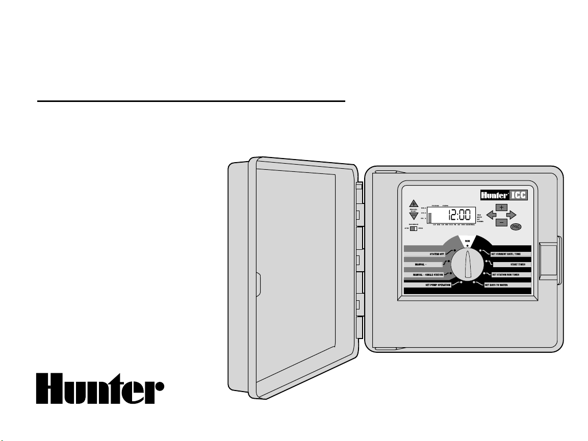
Finally, there’s an affordable, full-featured indoor/outdoor controller for commercial applications.
Hunter Industries is pleased to introduce the ICC – Institutional/Commercial Controller for commercial use. Designed with the needs of the customer
in mind, the ICC offers simplified dial programming and an impressive range of features typically found in controllers that cost twice as much.
The ICC is very much a professional grade product. The controller’s large cabinet provides ample room for wiring. And the ICC is filled with essential
features that landscapes demand like a rain sensor bypass circuit, primary and secondary power surge protection, seasonal adjustment/water
budgeting, simultaneous program operation, programmable pump/master valve circuit, programmable rain delay, cycle and soak, four independent
programs with four different day scheduling choices and eight start times each, plus much more.
The ICC is so easy to use that you’ll need this user guide ver y little after installation. If you do have a question about the controller, refer to this
booklet or to the abbreviated instructions inside the door.
You can be sure that you’ve chosen with confidence. The ICC is a controller that does the job efficiently and economically.
1
Page 6
A
1 2 3
4
10
98
11
13
14
15
17
16
19
18
12
B
B
C
5
6
7
ALL STATIONS PROGRAM
ICC COMPONENTS ..................................................................................................................
2
Page 7

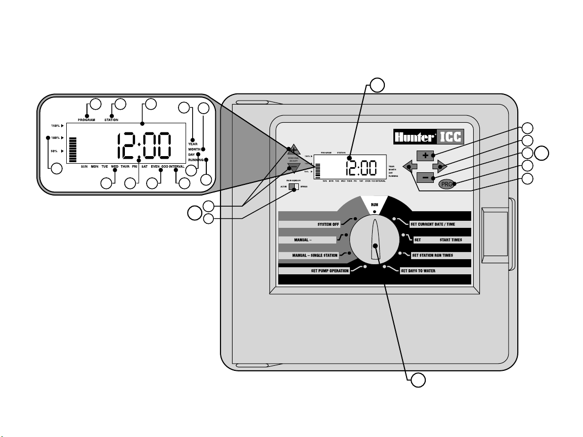
This section will give you a brief overview of some of the components
on the ICC. Each item will be discussed in further detail later, however
this section can be helpful in getting acquainted with the different
options available.
A – LCD Display
1. Program Selector – Identifies the program in use A, B, C, or D.
2. Station Number – Identifies currently selected station number.
3. Main Display – Indicates various times, values, and programmed
information.
4. Year – Arrow identifies current calendar year.
5. Month – Arrow identifies current calendar month.
6. Day – Arrow identifies current calendar day.
7. Running – Arrow indicates when watering is occurring.
8. Day of the Week – Arrow identifies days of the week to water.
You can also select odd or even and an interval watering schedule.
9. Odd/Even Watering – Arrow identifies if odd or even watering
is selected.
10. Interval – Arrow identifies if interval watering has been selected.
11. Seasonal Adjust – Displays in increments of 10%, the percentage
of seasonal adjust that has been selected.
12. Start time – Identifies selected start time. (Only appears on LCD
main display when SET PROGRAM START TIMES is selected.)
B – Control Buttons and Switches
13. Button – Increases the selected flashing display.
14.
Button – Decreases the selected flashing display.
Button – Advances the selected flashing display to the next
15.
item. Also to start a manual cycle.
16.
Button – Returns the selected flashing display to the previous
item.
Button – Selects programs A, B, C, and D. Also to start a test
17.
program cycle.
18. Rain Sensor Switch – Allows user to bypass weather sensor if one
is installed.
19.
and Buttons – Used to increase or decrease the seasonal
adjust option.
A key feature of the ICC is its clear, easy-to-use dial design that makes
programming a snap. All essential keypad functions are clearly marked
to eliminate the confusion that’s a characteristic of so many other
controllers.
C – Control Dial
Run – Normal dial position for all controller automatic and manual
operation.
Set Current Date/Time – Allows current date and clock time to
be set.
Set Program Start Times – Allows 1 to 8 start times to be enabled in
each program.
Set Station Run Times – Allows user to set each station run time.
Set Days to Water – Allows user to select individual days to water or
to select an odd, even, or interval watering schedule.
Set Pump Operation – Allows user to turn off pump or master valve
for specific stations.
Manual – Single Station – Allows user to activate a one time watering
of a single station.
Manual – All Stations – Allows user to activate a one time watering of
all stations or a few selected stations in a selected program.
System Off – Allows user to discontinue all programs and stop all
watering until the dial is returned to the RUN position.
3
Page 8

ICC COMPONENTS – WIRING CABINET .............................................................................
9V Battery
22 23
21
20
24
25
4
Page 9

D – Wiring Cabinet
20. 9-Volt Batter y – The alkaline battery keeps time during power
outages or if the transformer is disconnected. The user may also
program the controller without AC power.
21. Reset Button – This button will restart the computer in case of
power surge or display freezing. No programmed data will be lost.
22. Power Module Area – Used to attach transformer, master valve,
and other systems from their source to the controller.
23. Transformer – A transformer is installed in the controller to route
AC power from the power cable to the terminal strip area and to
ground the controller.
24. Junction Box – This box contains a terminal strip for connecting
115 volt and 230 volt power connections.
25. Station Modules – There are 4 (plastic cabinet) or 6 (metal or
stainless steel cabinet) modular positions inside the controller.
With the addition of 4 or 8 station ICM modules, you have the
ability to run anywhere from 8 to 32 stations (plastic cabinet),
and 8 to 48 stations (metal and stainless steel cabinet).
5
Page 10
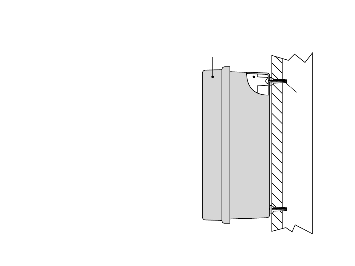
ICC Controller
Plastic Cabinet
Screw with
Screw Anchor
Cutaway View
MOUNTING THE CONTROLLER TO WALL ..........................................................................
Wall Mount for Plastic, Metal or Stainless Steel Cabinet
All necessary hardware is included for most installations.
1. Select a location as close as possible to a standard electrical outlet
that is not controlled by a light switch.
2. Using the enclosed mounting template, mark the hole locations on
the wall. It should be in an easily accessible location at eye level
if possible.
3. Drill a ¼ " (6 mm) hole at each mark.
4. Install screw anchors into holes if attaching controller to drywall,
5. Remove the door and front panel from the controller. The front door
6. Remove the protective plastic covering from around the appropriate
7. Holding the controller cabinet, line up the holes in the cabinet with
8. Drive a screw through each hole and secure snugly but do not
masonry, or plaster walls.
can be removed by pulling out the hinge pin.
mounting bosses on the back of the controller cabinet by pushing a
screwdriver through them.
the wall anchors or pilot holes.
over tighten.
6
Page 11

MOUNTING THE CONTROLLER (ICC METAL PEDESTAL) ................................................
Finish Grade
ICC Pedestal
Concrete
(Slope to Drain)
3
/4" (19 mm) Conduit for 120/230 VAC 1 1/4", 1 1/2" or 2"
(32, 40 or 50 mm)
Conduit For Valve Wires
ICC Controller
Metal Cabinet
Pedestal Mount, Metal or Stainless Steel Cabinet
1. Assemble the mounting template using the instructions provided
with the pedestal.
2. Using the enclosed mounting template, locate the bolts two inches
deep in the concrete pad, in the locations indicated. The pad can be
any size but at least a two-foot square is recommended.
3. Level the mounting bolts before the concrete sets.
4. After the concrete sets, remove the door of the pedestal and slide
the pedestal down onto the four bolts. Secure the pedestal to the
bolts using the enclosed washers and nuts.
5. Remove the door and faceplate of the ICC and attach the metal
cabinet of the ICC to the top of the pedestal using the enclosed
hardware in the pedestal.
6. Replace the pedestal door first and then replace the faceplate and the
cabinet door. The pedestal door cannot be removed or replaced when
the cabinet door is closed.
7
Page 12

MOUNTING THE CONTROLLER (ICC-800PP/ICC-800SAT) ..............................................
Thread Length 2.50" Min
Above Concrete
4"
26" Min
12.50"
5.00"
GCBL Wiring (Required For IMMS)
(3" Max Above Concrete)
Field Wiring
(3" Max Above Concrete)
Te
mplate
AC Power Wire S\P
(3" Max Above Concrete)
21" Min
Concrete Foundation
Plastic Pedestal Mounting
1. Set concrete forms using the installation instructions provided
with the controller. Allow 2" of conduit above the surface of the
concrete pad.
2. Assemble the mounting template. Twist one nut on each of the four
J-bolts and slide each bolt through the template. Put a washer and
nut on each J-bolt to secure it to the template (allow 2 ½" of thread
protruding above each nut).
3. Level the mounting template before the concrete sets.
4. After the concrete sets, remove the nuts and washers from the four
J-bolts slide the pedestal over the bolts. Secure the pedestal to the
bolts using the enclosed washers and nuts.
8
Page 13
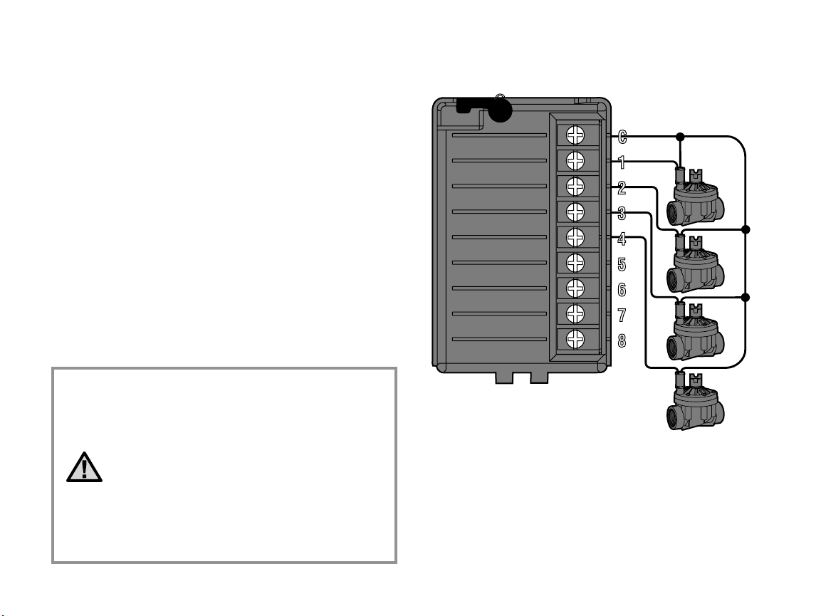
CONNECTING VALVES ............................................................................................................
Valve Common Wire
Valve 4
Va
lve 3
Valve 2
Valve 1
Valve
Wires
1. Route valve wires between control valve location and controller.
2. At valves, attach a common wire to either solenoid wire of all valves.
This is most commonly a white colored wire. Attach a separate
control wire to the remaining wire of each valve. All wire splice
connections should be done using waterproof connectors.
3. Open hinged faceplate on the controller to access the terminal
strip area.
4. Route valve wires through the conduit and attach conduit to the
controller at the large conduit opening on the right side of the
bottom of the cabinet. The conduit opening has a triple knockout to
accommodate 1", 1¼" or 1½" (25, 32 or 40 mm) conduit. Each
section can be easily removed using a knife. Refer to the conduit
sizing chart on page 31 in the Frequently Asked Questions section if
you are not sure what size conduit will work for your installation.
5. Strip ½" (13 mm) of insulation from ends of all wires. Secure valve
common wire to
or power module. Then attach all individual valve control wires to
appropriate station terminals.
C (Common) terminal on any of the valve modules
NOTE: Although it is usually best to connect all
field wires prior to powering up the controller, it is
not necessary with the ICC. After powering up the
controller, attach the common wire to the terminal
strip as described above. Then touch each wire
to the terminal marked TEST to identify the valve
location. Each valve will open electrically when
the wire is touched to the TEST terminal. After
identifying the valve location, you may then insert
the wire into the appropriate terminal. This feature
allows you to sequence the valves in the most
logical order for the user without damaging the
controller by “sparking” the wires.
9
Page 14
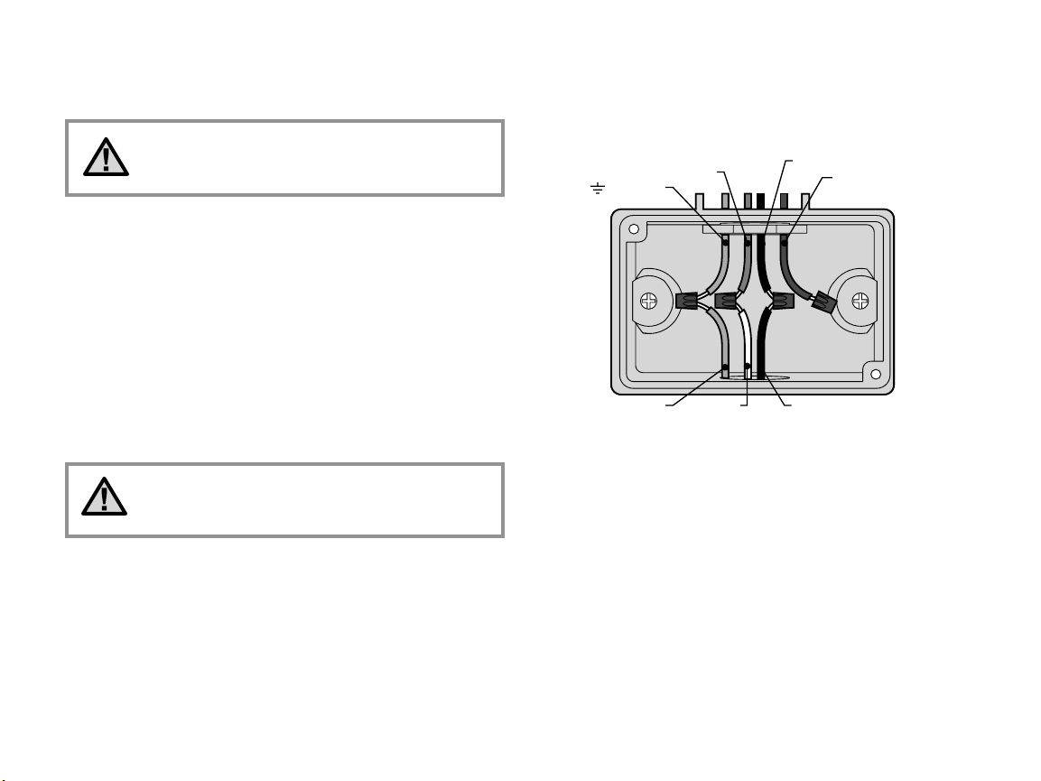
CONNECTING AC POWER (ICC-800) ....................................................................................
Figure 1 – Junction Box without Terminal Strip (120 Volt)
Green Wire
(Ground)
N Blue Wire (Neutral
)
120 Black Wire (120 Vo
lt)
230 Brown Wire
(Use only for 230 Volt
Connections )
Green Wire White Wire Black Wire
It is recommended that a licensed electrician
perform the following power installation.
1. Remove the cover from the junction box.
2. Strip ½" off of each wire.
3. For all connections, route the wires through the conduit opening
inside the junction box
4. For 120 volt connections twist the wires together using wire nuts as
shown in Figure 1.
5. Cap any unused wires. Replace faceplate of junction box and screw
into place.
Note: Wiring instructions for the ICC-800 SAT are
included in the controller installation instructions
supplied with the controller.
10
Page 15

Clamp
Grounding
Electrode
Figure 5 Power Module
Green Wire
(Ground)
N Blue Wire (Neutral
)
120 Black Wire (120 Volt)
Figure 3 – Junction Box with Terminal Strip (120 Volt)
Green Wire Blue Wire
Black Wire
230 Brown Wire
(230 Volt)
Green Wire
(Ground)
N Blue Wire (Neutral)
Figure 4– Junction Box with Terminal Strip (230 Volt)
Green Wire Blue Wire Brown Wire
Note: The terminal strip is used in ICC-801PL (International) and ICC-800M controllers.
230 Brown Wire
(230 Volt)
120 Black
Wire (120 Volt)
CONNECTING AC POWER (ICC-801PL AND ICC-800M/ICC-800SS) ..............................
1. Remove the cover from junction box.
2. Strip ½" off of each wire.
3. For all connections, route the wires through the conduit opening
inside the junction box.
4. For 120 volt connections see Figure 3. For 230 volt connections see
Figure 4.
5. Replace faceplate of junction box and screw into place.
Grounding The ICC
The ICC is equipped with built-in electrical surge protection. For this
system to function properly, the earth ground terminal on the power
module must be connected to a ground rod that is driven into the earth.
Important: Use a #10 (6 mm) or #8 (10 mm) bare wire to connect the
controller to the ground rod. Use a standard copper clad,
diameter, 8' (2.5 m) long ground rod.
To connect ground wire:
1. Feed the ground wire up through the large hole at the bottom of the
controller cabinet (the same hole used for the valve wires).
2. Loosen the screw on the GND terminal on the power module and
place the ground wire into the terminal. Tighten the screw so that the
ground wire is secure (see Figure 5).
5
8
/
" (1.6 cm)
11
Page 16

CONNECTING STATION MODULES ......................................................................................
The ICC controller is supplied with one factory-installed station module
for up to 8 stations. Additional modules may be added in increments of
4 or 8 stations to expand the controller’s station capability (maximum
of 32 stations with plastic cabinet and maximum of 48 stations with
metal, stainless steel cabinet or plastic pedestal). Additional modules
are purchased separately.
ICM modules now have a Positive-Lock™ feature that fastens the
module securely into the ICC. Rotating the Positive-Lock lever makes it
easy to lock or unlock the module(s).
1. When installing additional modules, you will need to turn AC power
off at the controller.
2. Rotate the Positive-Lock lever on the module clockwise to the
unlock position.
3. The module needs to be inserted into the next sequential position in
the back of the controller. Note: If you are using a 4-station module,
it must be in the last sequential position on the controller.
Example: For an area that needs 12 stations, the first module will
be an 8-station and the 4-station module will be below it. Note that
station numbers are identified on the back panel, not the individual
modules.
4. Insert the module into the controller’s expansion slot with the tab
end first (opposite side with the Positive-Lock lever).
5. Push the module into the expansion slot and rotate the lever counterclockwise (until the lever is flush with the side the module) to lock
the module in place.
6. Restore power to the controller. Turning the power off and on
again permits the microprocessor to recognize the newly installed
modules. You can also use the reset button on the back of the front
panel to reset the microprocessor to recognize additional modules.
Note: The Positive-Lock™ feature was added
to ICM modules date coded 12/02 or newer. The
modules will also work with older ICC units.
Positive-Lock™ Lever
12
Page 17

9V Battery
9V Battery
9V Battery
CONNECTING THE BATTERY (OPTIONAL) ..........................................................................
Connect a 9-volt alkaline battery (not included) to the battery terminals
and place in the batter y compartment in the controller cabinet. The
battery keeps time during power outages and allows the user to
program the controller without AC power. Watering will not occur
without AC power. Since this controller has non-volatile memory, the
program will be retained during a power outage even if no batter y
is installed.
13
Page 18

Common Wire
Master Valve
Master
Valve
Wire
Power Module
CONNECTING A MASTER VALVE .........................................................................................
NOTE: Complete this section only if you have
a master valve installed. A master valve is a
normally closed valve installed at the supply point
of the main line that opens only when the automatic
system is activated.
1. At the Master Valve, attach the common wire to either solenoid
wire of the valve. Attach a separate control wire to the remaining
solenoid wire.
2. Route the wires into the controller via the field wire conduit.
3. Connect either wire from Master Valve to the P/MV terminal.
Connect remaining wire to the C (Common) terminal.
14
Page 19

CONNECTING A PUMP START RELAY .................................................................................
Pump Relay Common Wire
Pump Relay Wire
Power Module
PSR Series
Pump Start Relay
To Pump
15' Minimum (4.5 m)
1. Route a wire pair from the pump relay into the controller housing.
NOTE: Complete this section only if you have a
pump and pump start relay installed. A pump start
relay is an electronic device that uses a signal
current from the irrigation controller to activate a
pump to provide water to your system.
The controller should be mounted at least 15 feet (4.5 m) away from
both the pump start relay and the pump. When a pump is to be operated
by the controller, a pump start relay must be used. Hunter offers a full
range a pump start relays for most applications.
2. Connect the pump relay common wire to the terminal slot
(Common) and the remaining wire from the pump relay to the P/MV
screw slot.
Relay holding current draw must not exceed .28 amps.
Do not connect the controller directly to the pump –
damage to controller will result.
C
15
Page 20

Power Module
Weather Sensor
CONNECTING A WEATHER SENSOR (NOT INCLUDED) ...................................................
A Hunter Mini-Clik® rain sensor or other type of micro-switch weather
sensor may be connected to the ICC. The purpose of this sensor is to
stop watering when precipitation is sufficient. The sensor connects
directly to the controller and allows you to easily override the sensor by
using the Rain Sensor bypass switch on the controller.
1. Route the wires from the rain sensor up through the same conduit
used for valve wiring.
2. Remove the jumper from the two SEN terminals on the power
module.
3. Connect one wire to the SEN terminal and one to the other SEN
terminal on the power module
NOTE: If the rain sensor switch is left in the ACTIVE
position and no sensor is connected, and the
jumper has been removed, the display will read
SEN OFF and no irrigation will occur. To eliminate
this problem when no sensor is connected, leave
the switch in the BYPASS position or install a short
jumper wire between the sensor terminals.
For more information on Mini-Clik sensors, visit Hunter's Web site at
http://www.HunterIndustries.com or contact your local dealer.
16
Page 21

CONNECTING AN SRR OR ICR REMOTE CONTROL (NOT INCLUDED) .........................
Controller
Receiver
Outdoor Installation
(Temporary Connection
of Receiver Only)
Indoor Installation
1
/2" Thread
To
Controller
Pre-assembled Assembled
Power Module
Blue
White
Red
Smart Port
Wi
ring Harness
The ICC controller is shipped with a SmartPort® wiring harness,
allowing for fast and easy use of the Hunter SRR or ICR remote control.
The remote makes it possible for contractors and end users alike to
operate a system without having to walk back and forth to the controller.
To utilize the SRR/ICR Remote Control System you must install the
SmartPort outlet.
1. Install a ½" female threaded “Tee” in the field wiring conduit
approximately 12" below the ICC.
2. Feed the red, white, and blue wires of the harness through the base
of the “Tee” and into the wiring compartment as shown in below.
3. Screw the SmartPort harness housing into the “Tee” as shown.
4. Access the terminal strip area and attach the red wire to the bottom
most AC screw slot, attach the white wire to the upper AC screw slot
and attach the blue wire to the screw slot marked “REM.”
The SmartPort is now ready for remote control use. Please refer to the
SRR or ICR owner’s manual for further information or contact your local
Hunter distributor for ordering information.
17
Page 22

CONNECTING AN SRR OR ICR REMOTE CONTROL (CONTINUED) ...............................
NOTE: Any extension of the wiring on the Sm artPort® may result in an error message in the controller display and possible
malfunction of the remote unit due to radio interference. In some situations, lengthening of the harness may work fine,
in others it may not work at all (it is site specific). In either case, extending the wiring harness should be done using
shielded cable to minimize the possible effects of electrical noise. For easiest installation, order a new Hunter SmartPort
shielded cable wiring harness (part #SRR-SCWH) with a full 25 feet of shielded cable.
CONNECTING TO THE HUNTER IRRIGATION MANAGEMENT AND
MONITORING SYSTEM™ (NOT INCLUDED) .......................................................................
With the IMMS™, automatic irrigation systems at multiple sites or multiple controllers at a single site can be programmed for functions that would
typically be handled directly at each controller. Scheduling of days to water, run times, start times, cycle and soak operations and more can now be
done from a single computer at a desk miles away from the actual installation. In addition, scheduled operation of non-irrigation components also in
use at these sites – e.g., lighting systems at athletic fields, fountains at shopping centers – as well as pumps and sensors can also be programmed
and monitored from a single central location. A key function of the IMMS is its ability to monitor changing conditions. With the aid of such options
as flow sensors, rain sensors and other weather-sensing devices, the IMMS can receive reports on the current condition at ever y site it is linked
with and then respond with the necessary adjustments should any of those conditions go beyond the limits that have been defined. It’s able to team
with any or all of the standard automatic controllers in the Hunter line-up, from the SRC to the Pro-C to the ICC. Plus, it’s a system that’s easy and
affordable to upgrade, making it possible to accommodate an expanding network of controllers. For more information on the IMMS software, contact
your local Hunter dealer.
The Hunter ICC-800 SAT Field Satellite Controllers are supplied with an IMMS Site or Controller Interface already prewired to the ICC Controller.
Installation is as simple as connecting AC power to and communication wires to the Controller and you're ready to operate the ICC from a central
computer. Reference IMMS Installation and Operating Instructions for further information.
The ICC-800 PL, ICC-800M/-800SS are all capable of operating with IMMS. Separate Site or Controller Inter face hardware is required (ordered
separately). For more information on IMMS, contact your local Hunter dealer or visit the Hunter website at http://www.HunterIndustries.com
POWER FAILURES ...................................................................................................................
Due to the possibility of power failures, the controller has nonvolatile memory to preserve the program indefinitely. If no 9-volt battery is installed, the
controller will freeze time when the power goes out and resume, keeping time after power has been restored. If a battery is installed, the 9-volt battery
back up will keep time so the clock and calendar will be intact for up to three days. There is no default program so there will be no surprise watering.
18
Page 23

SPRINKLER SYSTEM FUNDAMENTALS .............................................................................
Valve 1
Station 1
Station 2
Station 3
Station 6
Valve 2
Valve 3
Valve 5
ICC Controller
Station 5
Valve 4
Station 4
®
® ®
®
Valve 6
®
Valve 7
®
®
®
Station 7
There are three main components that are involved with all automatic
sprinkler systems that are made today. They are the controller, control
valves, and the sprinklers.
The controller is what makes the whole system operate efficiently. It is
technically the brain of the entire system, instructing the valves when to
supply water to the sprinklers and for how long to do so. The sprinklers,
in turn, will direct the water towards the surrounding plants and lawn.
The valve controls a group of sprinklers called a watering station. These
stations are laid out in a fashion according to the type of plant life that
exists there, the locations of the plants, and the maximum amount of
water that can be pumped to the location. Each valve is connected via
wire to the terminal strip area inside of the controller. Here the wire is
connected to a number that corresponds to the valve’s station number.
The controller will operate the valves in order, only one at a time. When
a valve has completed it’s watering; it will switch to the next station that
has been programmed. This process is called the watering cycle. The
information pertaining to the watering times of the individual stations
and the duration of them is called a program
.
19
Page 24

CREATING A WATERING SCHEDULE ...................................................................................
For most consumers, it is much easier to plan your specific watering
schedule onto paper before actually programming the information
into the controller. It’s also handy to have a written record of your
programming information for easy reference.
There are some guidelines that should followed when determining
when and how long to water. These factors are, the soil type, the part
of the landscape being watered, weather conditions, and the types
of sprinklers being used. Since there are so many different variables
that can determine your individual watering schedule; it is impossible
to give an exact schedule to follow. However, we have included some
guidelines to help you get started.
It is usually good to water one or two hours before
sunrise. Water pressure will be at optimum levels
during the early morning and the water can soak
into the roots of the plants while evaporation is
minimal. For most plants, watering during mid-day
or in the evening may cause plant damage or
possibly mildew.
Keep an eye out for evidence of under- or overwatering. Over-watering is most commonly
indicated by pools of water that take a long time to
soak in or evaporate, while under-watered
landscapes will show signs of discoloring and
dryness. Make programming changes immediately
when evidence is present.
HOW TO FILL OUT THE WATERING SCHEDULE ................................................................
Be sure to use a pencil when filling out this form. By using the included
example and the information below, you should have all the information
you need to construct your personal water schedule. There is an
example of a completed form on the following page.
Station Number and Location – Identify the station number, location
and the type of plant that is being watered.
Watering Day – Identify whether you want to use a calendar day,
interval, or an odd or even day schedule. For a calendar day schedule
circle the day of the week in which watering is desired. For an interval
20
schedule, indicate the desired interval number. And for an odd or even
day schedule, simply mark the corresponding box.
Program Start Times – Indicate the time of day that the program will
begin. Each program can have 1 to 8 start times. However, one start
time can run an entire program.
Station Run Time – Indicate the run time (1 minute to 2 hours or up to
12 hours on program D) for each station. Write “OFF” for any station
that you do not want to operate in the program.
Keep this schedule in a safe place for quick reference later, rather than
scrolling through program information on the controller.
Page 25

PROGRAM A
CALENDAR DAY
ODD/EVEN DAY
SU MO TU WE TH FR SA
ODD EVEN
LOCATION
1
STATION
STATION RUN TIME
PROGRAM
START
TIMES
HUNTER ICC
INTERVAL DAY
PROGRAM B PROGRAM C PROGRAM D
SU MO TU WE TH FR SA
ODD EVEN
3
SU MO TU WE TH FR SA
ODD EVEN
SU MO TU WE TH FR SA
ODD EVEN
2
3
4
5
6
7
8
1
2
3
4
5
6
7
8
9
STATION RUN TIME STATION RUN TIME STATION RUN TIME
NW Corner
NE Corner
Rear
SE Corner
SW Corner
Fr
ont Walk
Shrubs
0:15
0:15
0:15
0:15
0:10
0:10
6:00 AM
OFF
OFF
OFF
OFF
OFF
OFF
OFF
9:00 AM
OFF
OFF
OFF
OFF
OFF
OFF
OFF
X
0:20
21
Page 26

PROGRAMMING FUNDAMENTALS .....................................................................................
A watering program can be created to operate valves in numerical
sequence one at a time. All that is required to create a watering program
is to:
1. Select a program (
controller (it is recommended to start with Program A).
2. Set a program start time (only one program start time is required to
activate a watering program).
3. Set the run time for each valve assigned to the program, and
4. Set the days that you would like the watering program to run.
For the controller and it’s selected program to operate automatically,
there are three components that must exist: When to water
(or Program Start Times), how long to water (or Station Run Times),
what day of the week to water (or Days to Water).
We have included an example that will better illustrate the operation
of a program. Let’s say you have a program start time set for 6:00
Stations 1 and 2 are going to have a run time of 15 minutes and Station
3 is set for 10 minutes. Please note that Stations 4, 5, etc. have not been
included in this program, we will water them on separate programs.
Going back to our previous example, at 6:00
activate the watering cycle. The sprinklers on Station 1 will run for
15 minutes and then shut off. The controller will automatically activate
Station 2 sprinklers. These sprinklers will also run for 15 minutes and
then shut off. Then, watering on Station 3 will begin. The sprinklers will
turn on for 20 minutes and shut off. The controller will run all Stations
sequentially with Station 6 concluding the program at 7:30 A M.
As shown in the above example, only one program start time was
required to run the three different stations. The controller automatically
moves to the next station without the need for additional start times.
A, B, or C) by pressing the button on the
AM.
AM the controller will
We realize that many consumers will have variations in their plant
watering needs, so at Hunter we equipped the ICC with four different
programs: A, B, C, and D. These programs are completely independent
of each other and give you the ability to have four coexisting timers in
one controller. The only exception is program D, which can be used as a
drip irrigation program. Any station used in program A, B, or C can not
be used in pro-gram D. This prevents the accidental assignment of a
rotor or spray zone to program D, the drip program, which could lead to
excessive watering.
Program D can run concurrently with Program A, B, or C. For example,
using more than one program would enable you to water the lawn Stations
1, 2, and 3 on program A, Station 4 to soak the flowers with drip irrigation
on program D, and Station 5 to water the shrubs on program B. However,
it is not absolutely necessary to use this feature. Many users prefer the
simplicity of using one program for all their watering needs. The additional
programs are provided for your convenience should the need arise.
22
Page 27

Sprinklers On
Station 2 begin to
water at 6:15
AM
PROGRAM A
CALENDAR DAY
ODD/EVEN DAY
SU MO TU WE TH FR SA
ODD EVEN
LOCATION
1
STATION
STATION RUN TIME
PROGRAM
START
TIMES
HUNTER ICC
INTERVAL DAY
PROGRAM B
SU MO TU WE TH FR SA
ODD EVEN
3
2
3
4
5
6
7
8
1
2
3
4
5
6
7
8
9
STATION RUN TIME
NW Corner
NE Corner
Rear
SE Corner
SW Corner
Fr
ont Walk
Shrubs
0:15
0:15
0:15
0:15
0:10
0:20
6:00 AM
OFF
OFF
OFF
OFF
OFF
OFF
OFF
9:00 AM
OFF
OFF
OFF
OFF
OFF
OFF
OFF
X
0:20
12
6
39
12
6
39
12
6
39
Station 1
Station 2
Station 3
®
®
®
®
®
®
Sprinklers On
Station 1 begin to
water at 6:00
AM
Sprinklers Off
Station 1 turns off
at 6:15
AM
Sprinklers Off
Station 2 turns off
at 6:30
AM
Sprinklers On
Station 3 begin to
water at 6:30
AM
Sprinklers Off
Station 3 turns off
at 6:50
AM
1st Program
Start Time at
6:00 AM
Cycle Ends at 7:30 AM
(After Station 6
Finishes Watering)
Automatically
advances to
next station
Automatically
advances to
next station
15 min.
15 min.
20 min.
To
tal Cycle of Program A = 50 minutes
Program A
PROGRAMMING FUNDAMENTALS EXAMPLE ..................................................................
23
Page 28

PROGRAMMING THE CONTROLLER ...................................................................................
ALL STATIONS PROGRAM
Two key features of the ICC that make programming a snap are its clear,
easy-to-read LCD display and its easy-to-use dial design.
The ICC display shows time and day when the controller is idle.
The display changes when the dial is rotated to indicate the specific
programming information to enter. When programming, the flashing
portion of the display can be changed by pressing the or buttons.
To change something that is not flashing, press or until desired
field is flashing.
The ICC controller offers maximum scheduling flexibility including
four programs, each with up to 8 daily start times, permitting plants
with different watering requirements to be separated on different day
schedules. Multiple start times permit morning, afternoon and evening
watering, perfect for the establishment of new lawns and thirsty annual
flowers. A built in 365-day calendar clock accommodates odd/even
watering restrictions without requiring monthly reprogramming.
Or, just simply designate the days of the week you want to water or use
the convenient day inter val watering. The ICC makes it easy.
NOTE: A basic pro gramming rule is that wh atever
symbol or character is flashing will be the item
programme d. For inst an ce , if the hour is fl ashing
when setting the time, the hour can be changed or
programme d. For illu st ra tion purposes, flashing
character s are in
Date And Tim e
To activate a program in your controller, you must enter the following
information:
1. Set current day and time – turn dial to SET CURRENT DATE/TIME
2. Set what time of day you would like the program to start – turn dial to
SET PROGRAM START TIMES
3. Set how long each valve will water – turn dial to SET STATION
RUN TIMES.
4. Set the day(s) you would like the program to water – turn dial to
SET DAYS TO WATER
NOTE: All stations operate in numerical order. Only
one program start time is required to activate all
stations in the watering program.
GRAY type. Setting The Current
.
.
.
24
Page 29

Setting The Current Date And Time
PM
SET CURRENT
DATE/ TIME
SET PROGRAM
START TIMES
PM
START TIME
1. Turn the dial to the SET
CURRENT DATE/TIME position.
2. The current year will be flashing
in the display. Use the and
buttons to change the year.
After setting the correct year,
push the button to proceed
to setting the month.
3. The month and day will be in the
4. The day will be flashing: Use the
5. The time will be displayed: Use
display. The month will be
flashing. Use the and
buttons to change the month.
Press the button to proceed
to setting the day.
and buttons to change the
day of the month. (The day
of the week is automatically
indicated by an arrow in the
bottom of the display pointing
to the day.) Press the button
to proceed to setting the time.
and buttons to select
the
AM, PM, or 24 hr. Press the
button to move to hours. Hours
will be flashing. Use the and
buttons to change the hour
shown on the display. Press the
button to move onto the minutes. Minutes will be
flashing. Use the and buttons to change the minutes shown
in the display. The date, day, and time have now been set.
Setting Program Start Time
1. Turn the dial to the SET
PROGRAM START TIMES
position.
2. The factory preset is set on
program A. If necessary you
can select program B, C, or D
by pressing the button.
3. Use the and buttons
to change the start time.
(Advances in 15-minute
increments.)
4. Press the
the next start time, or for
the next program.
One start time will activate stations sequentially in that program one
at a time. Multiple start times in a program can be used for separate
morning, afternoon, or evening watering cycles. Do not enter a start
time for each station.
button to select
NOTE: Regardless of the order in which the start
times are entered, the ICC will always arrange the
start times in chronological order when the dial is
moved off the SET PROGRAM START TIMES position.
25
Page 30

PROGRAMMING THE CONTROLLER (continued) ..............................................................
SET PROGRAM
START TIMES
PM
START TIME
SET STATION
RUN TIME
S
START TIME
START TIME
Eliminating A Program Start Time
With the dial set to the SET
PROGRAM START TIMES
position, push the and
buttons until you reach 12:00 AM
(Midnight). From this position
push the button once to reach
the OFF position.
NOTE: If a program has all eight start times
turned off, then that program is off (all other
program details are retained). Because there are
no start times, there will be no watering with that
program. This is a convenient way to stop watering
on one program only without turning the dial to the
off position.
Setting Station Run Times (Length of Watering for Each Area)
1. Turn the dial to the SET
STATION RUN TIMES position.
2. The display will show the last
program selected (A, B, C, or
D). You can switch to another
program by pressing
the button.
3. Use the and buttons to
change the station run time on
the display.
4. Press the
to the next station.
5. Repeat steps 4 and 5 for each
station.
6. You may set station run times
from 1 minute to 2 hours. If the
station is assigned program
the run time can be set for up to 12 hours.
7. You can move between programs while staying on the same station.
However, it is recommended that one program is completed before
going on to the next program. Jumping between programs can be
confusing and may result in program errors.
button to advance
D,
26
Page 31

NOTE: If a station is assigned a run time on program
SET DAYS
WATER
A, B, or C, then that station cannot be assigned
to Program D. If this is attempted, the word USED
will appear in the display. Likewise, a station with
a run time on Program D cannot be assigned to
program A, B, or C. This is to prevent the accidental
assignment of a rotor or spray zone to the D program
which is normally reserved for drip applications.
Setting Days To Water
1. Turn the dial to the SET DAYS
TO WATER position.
2. The display will show the last
program selected (
D) the station number selected,
and the run time for that
station will be flashing. You
can switch to another program
by pressing the button.
3. The controller displays
currently programmed active
day schedule information. This
dial position provides four different water day options: choose to
water on specific days of the week, you can choose interval watering,
or choose to water on odd days or even days. Each program can only
operate using one type of water day option.
A, B, C, or
Selecting Specific Days of the Week to Water
1. With the arrow cursor on a specific day (the cursor always starts
with Sunday), press the button to activate a particular day of the
week to water. Press the button to cancel watering for that day.
After pressing a button the cursor automatically advances to the
next day.
2. Repeat step 1 until desired days have been selected. The selected
days arrows will show on the display to indicate their status as ON.
The last solid arrow is the last day of watering for that program.
Selecting Odd or Even Days to Water
This feature uses a numbered day
of the month for watering instead
of specific days of the week (Odd
days 1st, 3rd, 5th, etc.; Even days
2nd, 4th, 6th, etc.).
1. Press the button until the arrow cursor is above either EVEN or
ODD on the display.
2. Press the button to select or the button to cancel either Odd
Days or Even Days. The previous selected days of the week will
revert to active if Odd Days or Even Days is cancelled.
NOTE: The 31st of any month and February 29th are
always “off” days if Odd watering is selected.
27
Page 32

PROGRAMMING THE CONTROLLER (continued) ..............................................................
INTERVAL DAYS REMAINING
RUN
ACTIVE
BYPASS
SYSTEM OFF
RUN
Selecting Interval Watering
This feature is convenient if you want to have a more consistent
watering schedule without having to worry about the day of the week
or the date. The interval you select is the amount of days between
watering. The days remaining indicates how many days until the
next watering. For example if you select an interval of 4 with 1 days
remaining, watering will begin tomorrow at the scheduled time.
1. Turn the dial to SET DAYS TO
WATER the triangle above
Sunday should be flashing.
2. Use the button and move
the flashing arrow cursor
above the INTERVAL
designator.
3. Press the
display will now show two
numbers, the interval and the
days remaining in the interval.
4. The number of days between waterings, or the interval will be
flashing. Use the
days desired between waterings.
5. Press the
flashing. Use the and buttons to select the number of days
until the next desired watering. One day remaining means it will
water the next day.
After programming, set dial to RUN to enable automatic execution of all
selected programs and start times.
button. The
and buttons to select the number of
button. The days remaining in the interval are now
Run
After programming is complete,
turn the dial to RUN to enable
automatic execution of all selected
programs and start times. Watering
will not occur unless dial is in the
RUN position.
Weather Sensor Bypass
With this built-in feature,
there is no need for an
additional manual bypass
switch when using rain
sensors (the ICC works
with the Hunter Mini-Clik®,
plus some other rain, wind,
and freeze sensors on the market today). If the system is preventing
system operation (or no sensor is installed and the switch is in the
ACTIVE position), SEN OFF will be displayed. Simply move the switch
to BYPASS and the weather sensor will be bypassed. This allows you to
use the system.
System Off
Valves currently watering will be
shut off after the dial is turned
to the SYSTEM OFF position for
two seconds. All active programs
are discontinued and watering is
stopped. To return controller to
normal automatic operation,
simply return dial to RUN position.
28
Page 33

MANUAL SINGLE
STATION
Manually Run A Single Station
MANUAL ALL
STATION
1. Turn the dial to the MANUAL-
2. Station run time will flash in
3. Turn the dial to the RUN
Manually Run All Stations
1. Turn the dial to MANUAL-ALL
2. You can select program
3. Press the
4. Station run time will flash in
SINGLE STATION position.
the display. Use the button
to move to the desired station.
You may then use the
and buttons to select the
amount of time for a station
to water.
position to run the station
(only the designated station
will water, then controller will return to automatic mode with no
change in the previously set program).
STATIONS.
A, B, C, or D by pressing the
button.
button until
desired starting station is
displayed.
the display. Use the and
buttons to select the amount of run time for the station to water
if different from the run time displayed.
5. Use the button to move to the next station.
6. Repeat steps 3 and 4 to customize each station if desired.
7. Press the button until desired starting station is displayed.
8. Return the dial to RUN (custom program will water the entire
program beginning with the station number last left in the display,
then controller will return to automatic mode with no change in the
previously set program).
NOTE: The station that is on the display when you
turn the dial to RUN, will be the first station to run.
The controller will then proceed to water in
sequential order only. It will not water previous
stations. Example: If you turn the dial to RUN with
the display reading station 3, the controller will
water Stations 3 through 9 in the program, but not
return to Stations 1 and 2.
One Touch Manual Start and Advance
You can also activate all stations to water without using the dial.
1. Hold down the button for 2 seconds.
2. This feature automatically defaults to program A. You can select
program B, C or D by pressing the button.
3. The station number will be flashing. Press the
scroll through the stations and use the and buttons to adjust
the station run times. (If no buttons are pressed during step 2 or 3,
the controller will automatically begin program A.)
4. Press the
button to scroll to the station you wish to begin with.
After a 2 second pause, the program will begin.
This feature is great for a quick cycle when extra watering is needed or
if you would like to scroll through the stations to inspect your system.
or button to
29
Page 34

PROGRAMMING THE CONTROLLER (continued) ..............................................................
Seasonal Adjustment
Seasonal Adjust is used to make global run time changes without
reprogramming the entire controller. This feature is perfect for
making small changes that are necessar y as the weather changes
without reprogramming the entire controller. For instance, hotter
times of the year may require a bit more water. Seasonal adjust can
be increased so that the stations will run longer than the programmed
time. Conversely, as Fall approaches, the seasonal adjust can be
reduced to allow for short watering durations.
To use the seasonal adjust, simply press the or seasonal
adjust buttons to set the percentage desired. The watering run time
can be adjusted from 10% to 150% of original program. The season
adjust can be changed at any time regardless of the programming dial
position. To view the new adjusted run time, simply turn the rotar y dial
to the SET RUN TIMES position, the displayed run time will be updated
accordingly as the seasonal adjustment is made. The seasonal
adjustment will affect all station run times programmed
NOTE: The controller should always be initially
programmed in the 100% position.
30
Page 35

SET PUMP
OPERATION
PUMP
PUMP
SYSTEM OFF
ADVANCED PROGRAMMING CAPABILITIES ......................................................................
There are four advanced features available to customize the ICC to more
complex watering requirements. Two of these features are “hidden” to
make accidentally programming them nearly impossible.
Set Pump/Master Valve Operation
The default is for all stations to have the master valve/pump start circuit
ON. The master valve/pump start can be set ON or OFF by station,
regardless of which program the station is assigned. This feature may
be utilized on systems where it is desirable for a booster pump not to
operate with certain zones.
To program pump operation:
1. Turn the dial to SET PUMP
OPERATION position.
2. Press the
toggle the Master valve/pump
start ON or OFF for the
specific station.
3. Press the
to the next station.
4. Repeat steps 2 and 3 for all
necessary stations.
or buttons to
button to advance
Programmable Rain Off
This feature permits the user to
stop all programmed waterings
for a designated period from 1 to 7
days. At the end of the Rain Delay,
the controller will resume normal
automatic operation.
1. Turn the dial to the SYSTEM
OFF position.
2. Press the button and a 1
will be displayed and the DAYS
icon will illuminate. The 1 will
be blinking at this point.
3. Press
desired (up to 7).
4. To validate this setting (and to make sure the controller comes back
on after the period is over), turn the dial back to the RUN position at
which time, OFF, a number and the DAYS icon all remain on.
5. Leave the dial in the RUN position.
as many times as needed to set the number of days off
NOTE: The days off remaining will decrease at
midnight of each day. When it goes to zero, the
display will show the normal time of day and
normal irrigation will resume at the next scheduled
start time.
31
Page 36

RUN
CYCLE
SET STATION
RUN TIME
S
SOAK
HIDDEN FEATURES .................................................................................................................
NOTE: The hidden features described below can
only be entered by starting with the dial in the RUN
position and holding down various buttons while
the knob is turned to various setup positions.
This makes it virtually impossible for someone to
stumble onto these features.
Cycle and Soak
The Cycle and Soak feature allows the user to split each station’s run
time into more usable, shorter duration waterings. This feature is
particularly applicable for slopes and tight soil (such as clay) because
Cycle and Soak will help prevent excessive run off. You should enter the
Cycle time as a fraction of the station’s watering time and the Soak time
as the minimum soak required before watering the next portion. The
total number of cycles is determined by taking the total programmed
station run time and dividing it by the Cycle time.
For example: Suppose Station 1 required 20 minutes worth of water
but after only 5 minutes, runoff occurred. However, after 10 minutes all
the water was absorbed. The solution would be to program 20 minutes
for the Station Run Time, 5 minutes for the Cycle time, and 10 minutes
for the Soak. Station 1 will then water for 5 minutes and then the rest
of the stations in the program will water. After all the other stations
have watered the controller will check to see if Station 1 had soaked
for at least 10 minutes. If it had, then Station 1 will water for another
5 minutes. This process would continue to repeat itself until Station 1
watered 4 times for 5 minutes each time, a total of 20 minutes.
1. Start with the dial in the RUN
position.
2. Press and hold the button
down while turning the dial to
the SET STATION RUN TIMES
position.
3. Release the
button. At this
point, the display will show the
station number, the cycle time
will be blinking. The CYCLE
and soak icons will also be lit.
4. Press the
or buttons to
increase or decrease the cycle
time from 1 to 60 minutes in
1 minute increments.
5. Press the
key to advance
to the next station and its
cycle time.
6. Pressing the
key will
display the previous station
and its cycle time.
7. Return the Dial to the RUN
position after setting all the
cycle and soak times.
32
Page 37

SET STATION
RUN TIME
S
RUN
DELAY
Setting the Soak Times
DELAY
It is only necessary to set a SOAK time if the accumulated CYCLE times
on any single program will not provide an adequate soak time. For
instance, if the sum of the cycle times for all stations in a program
exceeds 10 minutes and each station will require no more than 20
minutes of soak time, then the accumulated cycle times are sufficient
and no soak time will need to be programmed. However, if the
necessary soak time did exceed the 10 minutes, then a soak time
must be entered for those stations requiring a longer soak between
waterings. The soak time default is 10 minutes.
Pressing the button at any time while in the cycle time setup will
allow the user to enter the soak time setup for that station. Pressing
again will go back to the cycle time setup. The soak time works
identically to the cycle time setup except that the SOAK icon will be on
as opposed to the CYCLE icon.
NOTE: If the dial is moved from the SET STATION
RUN TIMES position, then the entire sequence of
going back to RUN and holding the
key down
must be repeated to reenter the cycle and soak
setup. The cycle and soak feature is a station
dependent function and will be used whenever the
station operates regardless of which program or
programs the station is assigned.
Programmable Delay Between Stations
This feature allows the user to insert a delay between when one station
turns off and the next station turns on. This is very helpful on systems
with slow closing valves or on pump systems that are operating near
maximum flow or have slow well recovery.
1. Start with the dial in the RUN
position.
2. Press and hold the button
down while turning the dial to
the SET STATION RUN TIMES
position.
3. Release the
button. At this
point the display will show a
delay time for all stations in
seconds, which will be blinking.
The DELAY icon shall also be lit
at this time.
4. The display will show “SEC”.
Use the
and buttons to
increase or decrease the delay
time between 0 and 10 minutes
in 1 second increments.
5. Pressing either the
button
or the button will allow for
programming a longer delay
between stations. The display
will show the delay in minutes.
6. Press the
and buttons to
increase or decrease the delay
time from 0 to 10 hours in 5
minute increments.
7. Return the dial to the RUN
position.
33
Page 38

DELAY
HIDDEN FEATURES (continued) ............................................................................................
NOTE: The Master Valve/Pump Start circuit will operate
during the first 20 seconds of any programmed delay to
aid in the closing of the valve and to avoid unnecessary
cycling of the pump. It is recommended that a pressure
relief valve be installed on the system should this 20
second delay be too long for a particular system.
Consult your pump contractor or supplier for details.
Clearing Controller’s Memory / Resetting Controller
If you feel that you have misprogrammed the controller, there is a
process that will reset the memory to factory defaults and erase all
programs and data that have been entered into the controller.
1. Turn the dial to the RUN position.
2. Remove battery.
3. Hold down the
4. While holding down the three buttons, press and release the reset
button on the back of the front panel, then release the three buttons.
Hold all buttons and reset until display flashes 12:00. All the memory
has been cleared and the controller may be reprogrammed.
button, the button, and the button simultaneously.
Hunter Quick Check™
Irrigation professionals are continuously looking for ways to more
efficiently and effectively diagnose programs in the field. Instead of having
to physically check each field wiring circuit for potential problems, the
user can run the Hunter Quick Check™ circuit test procedure. This circuit
diagnostic procedure is very beneficial because of its ability to aid in
quickly identifying “shorts” commonly caused by faulty solenoids or when
a bare common wire touches a bare station control wire.
To initiate the Hunter Quick Check test procedure; Press the
, buttons. In the standby mode, the LCD will display all segments
(helpful when troubleshooting display problems). Press the button
to begin the Quick Check test procedure. Within seconds, the system
searches all stations in an effort to detect a
high current path through the station terminals.
When a field wiring short is detected, an ERR
symbol preceded by the station number will
momentarily flash on the controller LCD display.
After the Hunter Quick Check completes running this circuit diagnostic
procedure, the controller returns to the automatic watering mode.
, ,
Test Program
The ICC allows the user a simplified method for running a test program.
This feature operates each station in numerical sequence, from the
lowest to the highest. You can start with any station. This is a great
feature to check the operation of your irrigation system.
To initiate the test program:
1. Press and hold the button. The station number will be flashing.
2. Press the
program to start with. Use the or button to set the run time up to
15 minutes. The run time needs to be entered only once.
3. After a 2 second pause, the test program will begin.
or button to scroll to the station you would like the test
FREQUENTLY ASKED QUESTIONS ......................................................................................
What Size Field Wiring Conduit Should I Use?
Locate the size conduit across the top and the wire size along the side. Where
the two intersect on the table tells you approximately how many wires will fill
the conduit. Example: 49 wires of 18 AWG will fit in 1½" conduit.
34
Wire Siz e 1" (2 5 mm) 1¼" (32 mm) 1½" (40 mm)
18 AWG 20 34 49
16 AWG 16 30 42
14 AWG 10 18 25
12 AWG
CONDUIT SIZ ES
7 15 20
Page 39

TROUBLESHOOTING GUIDE ..................................................................................................
PROBLEM CAUSES SOLUTIONS
The controller repeats itself or continu
ously watering even when it should not
be on/controller cycles over and over.
There is no display.
The display reads “ERR”.
The display reads “P ERR”.
The display reads a station number
and ERR, such as “2 ERR”.
The display reads “NO AC”.
The display reads “SEN OFF”.
Too many start times (user programming
-
error).
Check AC power wiring. Correct any errors.
Electrical noise is entering the system. Check the SmartPort® wiring harness. If
There is a ground fault in the wire to the
pump start or master valve.
There is a ground fault in the wire leading to
that station.
There is no AC power present to operate
controller/valves.
The rain sensor is interrupting irrigation or
not installed.
Only one start time per active program is
required. Refer to "Setting Program Start
Times"
on page 24.
the wires were extended then they will need
to be replaced with shielded cable. Contact
your local distributor for information on
shielded cable.
Check the master valve or pump start wire
for continuity. Replace or repair the broken
wire. Check that all wire connections are
good and water tight.
Check the station wire for continuity. Replace
or repair broken wire. Check that all wire
connections are good and water tight.
Check to see if the transformer is properly
installed.
Slide the Rain Sensor switch on front panel
to the bypass position to bypass rain sensor
circuit.
35
Page 40

TROUBLESHOOTING GUIDE (continued) .............................................................................
PROBLEM CAUSES SOLUTIONS
The controller does not start
automatically.
Rain sensor will not shut off system.
The controller recognizes 48 stations
all the time.
The controller does not respond to all
the stations. Example, the controller
has 24 stations but the display will
only go to 16 stations.
The controller is only recognizing eight
stations when multiple modules are
installed and/or there are not enough
start times for all stations.
Controller has display but will not
activate zone valves.
Possible programming error. Check to make sure start time is entered
correctly (note AM/PM setting as well).
Check to make sure watering day is active.
Incorrect sensor type wired directly into sensor circuit. (Jumper installed)
Microprocessor requires reset. Make sure AC power is connected. Reset
Controller does not recognize modules. Turn off the power to the controller and re-
The dial is in the START TIMES position and
not the STATION RUN TIMES position (see
page 26).
Primary power to controller incorrectly
wired. Controller receiving voltage too low
for valve operation.
Make sure sensor is microswitch type such
as Mini-Clik®.
controller using method described on
page 34.
move the battery. Check all module connec
tions to the controller. Power the controller
back up. The microprocessor will recognize
all modules.
Be sure dial is in correct position. Total
number of stations can be easily checked
by placing dial in SET STATION RUN TIMES
position and pressing the back arrow.
Check and correct 110 or 220 volt
connection. 110 volt may be incorrectly
wired as 220 volt.
-
36
Page 41

SPECIFICATIONS .....................................................................................................................
Operating Specifications
• Station Run Time: 1 minute to 2 hours (in 1-minute increments)
on programs A, B, and C. Up to 12 hours on program D. The longer
run time on program D is primarily to accommodate drip irrigation
applications.
• Start Times: 8 per day, per program, for up to 32 daily starts.
• Watering Schedule: 7-day calendar, interval watering up to a 31-day
interval or true odd or even day programming, made possible by the
365-day clock/calendar.
Electrical Specifications
• Transformer Input: 120VAC, 60Hz (230VAC, 50/60 Hz
International Use)
• Transformer Output: 25 VAC, 1.5 amp
• Station Output: 24VAC, .56 amps per station
• Maximum Output: 24VAC, 1.4 amps (includes Master Valve Circuit)
• Battery Backup: 9-volt alkaline battery (not included) used only for
time keeping during power outages, the nonvolatile memory
maintains program information
Dimensions
Plastic Cabinet Metal Cabinet Metal Pedestal
Height: 11" (28 cm) Height: 15¾" (40 cm) Height: 30" (76 cm)
Width: 12" (30.5 cm) Width: 11
Depth: 3¾" (9.5 cm) Depth: 4½" (11.4 cm) Depth: 4" (10 cm)
Default Settings
All stations are set to zero run time. This controller has a nonvolatile
memory that retains all entered program data even during power
outages, without need for a battery.
3
8
/
" (29 cm) Width:11
3
8
/
" (29 cm)
37
Page 42

Page 43

Page 44

FCC NOTICE ...............................................................................................................................
This controller generates radio frequency energy and may cause interference to radio and television reception. It has been type tested and found to
comply with the limits for a Class B computing device in accordance with the specifications in Subpart J of Part 15 of FCC Rules, which are designed
to provide reasonable protection against such interference in a residential installation. However, there is no guarantee that inter ference will not
occur in a particular installation. If this equipment does cause interference to radio or television reception, which can be determined by turning the
equipment off and on, the user is encouraged to tr y to correct the inter ference by one or more of the following measures:
• Reorient the receiving antenna
• Move the controller away from the receiver
• Plug the controller into a different outlet so that controller and receiver are on different branch circuits
If necessary, the user should consult the dealer or an experienced radio/television technician for additional suggestions. The user may find the
following booklet prepared by the Federal Communications Commission helpful: “How to Identify and Resolve Radio-TV Interference Problems.”
This booklet is available from the U.S. Government Printing Office, Washington, D.C., Stock No. 004-000-00345-4 (price – $2.00 postpaid).
Hunter Industries Incorporated • The Irrigation Innovators © 2005 Hunter Industries Incorporated
1940 Diamond Street • San Marcos, California 92078 • TEL: (1) 760-744-5240 • FAX: (1) 760-744-7461
www.HunterIndustries.com
P/N 700319 LIT-237 8/05
 Loading...