

Page 1

44202 07/08/2010
Page 2
2
Site Selection
Welcome
Table Of Contents
Introduction and Preparation ....................................................................................................................................................................................................................................... 2
Using is Manual ................................................................................................................................................................................................................................................................ 3
Installation ................................................................................................................................................................................................................................................................................4
Operation and Troubleshooting .................................................................................................................................................................................................................................14
Congratulations!
Your new Hunter ceiling fan is an addition to your home or office that will
provide comfort and reliable performance for many years. We are proud
to supply you with the best ceiling fan available anywhere in the world.
Before installing your fan, we recommend that you record the following
information for your records and warranty assistance. Refer to the Hunter
nameplate on the top of your fan for the proper information. Be sure to
save your receipt for your records.
Model Name
Model Number
Serial Number
Date Purchased
Place Purchased
Before Installation
Before installing your fan, be sure you can do the following:
• Locate the ceiling joist or other suitable support in the ceiling.
• Drill holes and install wood screws or expansion anchors.
• If you have a concrete ceiling, you will need M5 x 30 mm expansion
anchors and screws. (Sold separately)
• Identify and connect electrical wires.
• Lift 16 kg (40 lbs).
Site Selection and Preparation
Refer to the included booklet "Guide to Choosing and Preparing a Ceiling Fan Site" to determine the best location for your fan. e booklet also includes
information to ensure your fan support and outlet box meet applicable safety codes for ceiling fans.
Checking Your Fan Parts
Check your fan parts carefully. Unpack your fan parts as instructed by this manual to avoid damage. Be sure to save this manual for reference and save any
extra parts. If you have a damaged fan blade, please return all blades for replacement. If you are installing more than one fan, be sure to keep the blades in
sets, as shipped.
Optional Accessories
Hunter oers several accessories to complement your fan such as wall-mounted or remote speed controls and extension down-rods for ceilings higher than
8 feet (2.4 meters). To ensure wobble-free and stable performance, all Hunter fans use 2 cm inner-diameter pipe for extensions. Follow the instructions for
use and installation included with the Hunter accessory.
For quiet and optimum performance of your Hunter fan, use only Hunter speed controls and accessories.
Page 3
3
WARNING
?
How To Use is Manual
How to Use is Manual:
Be sure to read the entire manual before beginning installation and save
any extra parts for future use. is manual will help you install, operate,
and maintain your new fan. ese instructions are designed to make
installation and assembly as simple and efficient as possible. Each step has
four components:
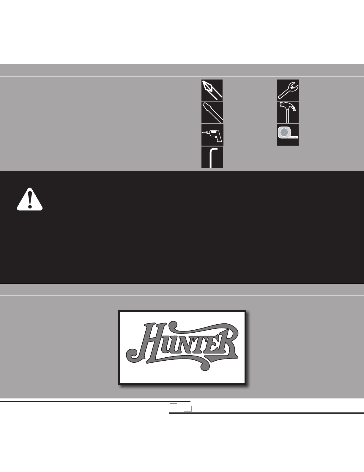
1. Each step is illustrated at the top of the page. e steps are numbered on
the side of each illustration.
2. e letter labels in the illustration (example: [a]) identify the included
parts and are described in the text instructions.
3. Text instructions beneath each illustration describe the procedure for
each step.
4. On the right side of each image, you will find a life-sized illustration of
necessary hardware. At the bottom of each illustration, there is a small
image that depicts the tools needed for each step. Each image correlates
to the following legend:
*used only for concrete ceilings
Screwdriver, Phillipshead
Screwdriver, Flat-head
Drill with 3,5 mm bit or
masonry bit*
Allen Wrench (included)
Wrench
Hammer
Tape Measure
WARNING!
• To avoid possible electrical shock, before installing your fan, disconnect the power by turning o the circuit breakers to the outlet
box and associated wall switch location. If you can not lock the circuit breakers in the o position, securely fasten a prominent
warning device, such as a tag, to the service panel.
• All wiring must be in accordance with national and local electrical codes. If you are unfamiliar with wiring, you should use a
qualified electrician and not attempt to install the fan.
• To reduce the risk of personal injury, do not bend the blade attachment system when installing, balancing, or cleaning the fan.
Never insert foreign objects between rotating blades.
• e fan blades cannot be placed lower than 7.5 feet (2.3 meters) from the oor.
• e installation site must have an all-pole switch with a separation gap of at least 3 mm.
• Be sure to read this manual carefully before beginning installation and save these instructions for later reference or warranty
assistance.
• To reduce the risk of personal injury, attach the fan directly to the support structure of the building according to these instructions
and use only the hardware supplied.
• e appliance is not intended for use by young children or inrm persons without supervision. Young children should be
supervised to ensure that they do not play with the appliance.
Page 4
4
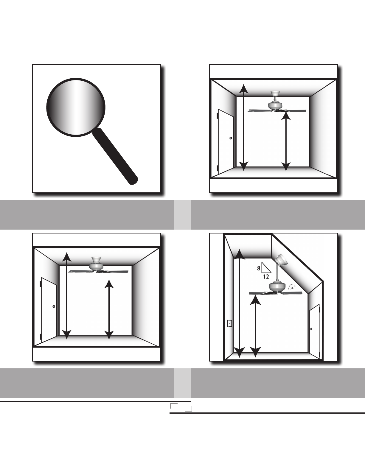
Standard Mounting is the most common way to mount a
ceiling fan. Standard mounting is recommended for ceilings
8 feet (2.4 meters) or higher.
Fan Mounting Options
ere are three different ways to mount your ceiling fan, depending
on your needs and the style of your ceiling.
Angle Mounting is especially useful for vaulted or angled ceilings.Flush Mounting is used when the ceiling is less than 8 feet (2.4
meters) high and fits closely to the ceiling.
8 ft.
8 ft.
8 ft.
7.5 ft.
7.5 ft.
7.5 ft.
2,3 m
2,3 m
2,3 m
2,4 m
2,4 m
2,4 m
Page 5
5
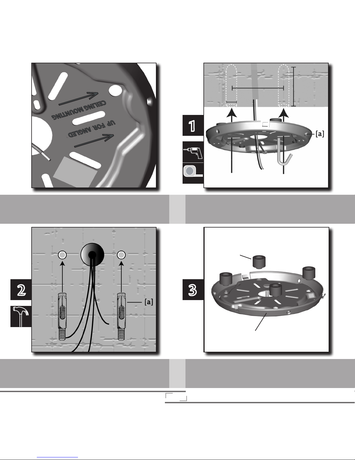
If angle mounting, Be sure to orient the ceiling plate so that the
arrows printed on the ceiling plate are pointing toward the ceiling
peak.
Drill one hole on each side of the supply mains for the expansion
anchors. Measure this distance using the oval slots in the ceiling
plate [a] as a guide.
2
1
Drive the M5 x 30 mm expansion anchors [a] into the holes until
the ends are flush with the ceiling.
Place the two rubber isolators [a] in the top of the
ceiling plate [b].
3
[a]
[b]
Page 6
6
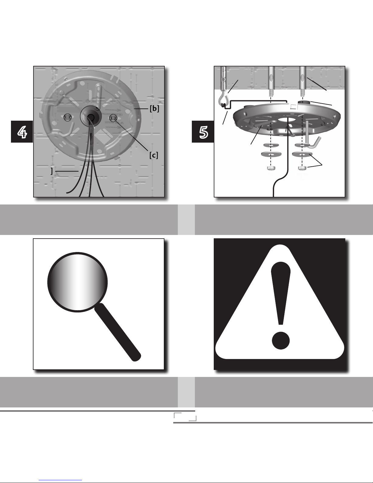
Pull the supply mains [a] through the center hole of the ceiling
plate [b] and align the two oval slots in the ceiling plate [b] with
the expansion anchors [c].
4
[a]
[b]
[c]
Secure the secondary support cable [a] to the support hook [b]
located in the ceiling. Align the Anchor bolts [c] with the oval slots
in the ceiling plate [d]. Push the Ceiling Plate onto the anchors [c]
until the rubber isolators [e] are tight against the ceiling. Place the
washer and screw [f] on the anchor and secure tightly
5
[f]
[d]
[b]
[c]
[e]
[a]
WARNING! To reduce the risk of re, electrical shock, or motor damage,
do not lift or carry the fan by the lead wires. To prevent damage to the
wires on the bottom of the fan assembly, do not sit fan on hard surface.
Use foam inside box as support. e pipe adapter has a special coating
on the threads. Do not remove this coating; it prevents the pipe from
unscrewing. Once assembled, do not remove the pipe.
If you are using a standard or angle mounting style to hang your fan,
follow steps 11 through 15 before proceeding to step 18. If you are
low profile mounting your fan, follow steps 16 through 17.
Page 7
7
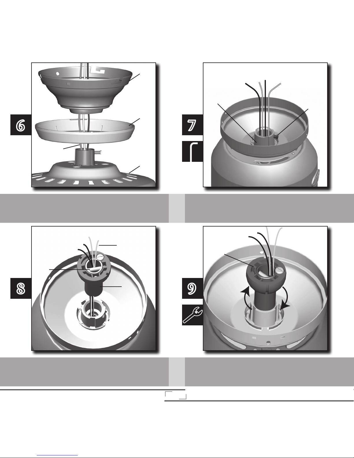
For standard or angle mounting:
With the fan motor [a] resting in the packaging, slide the canopy
trim ring [b] and canopy [c] onto the wires [d].
Loosen the setscrew [a] on the adapter [b].
6
7
[a]
[b]
[d]
[c]
Pull the wires [a] through one side of the pin [b] in the pipe
assembly [c].
Screw the pipe assembly [a] into the adapter until tight.
[a]
[b]
[c]
[a]
8 9
[a]
[b]
Page 8
8
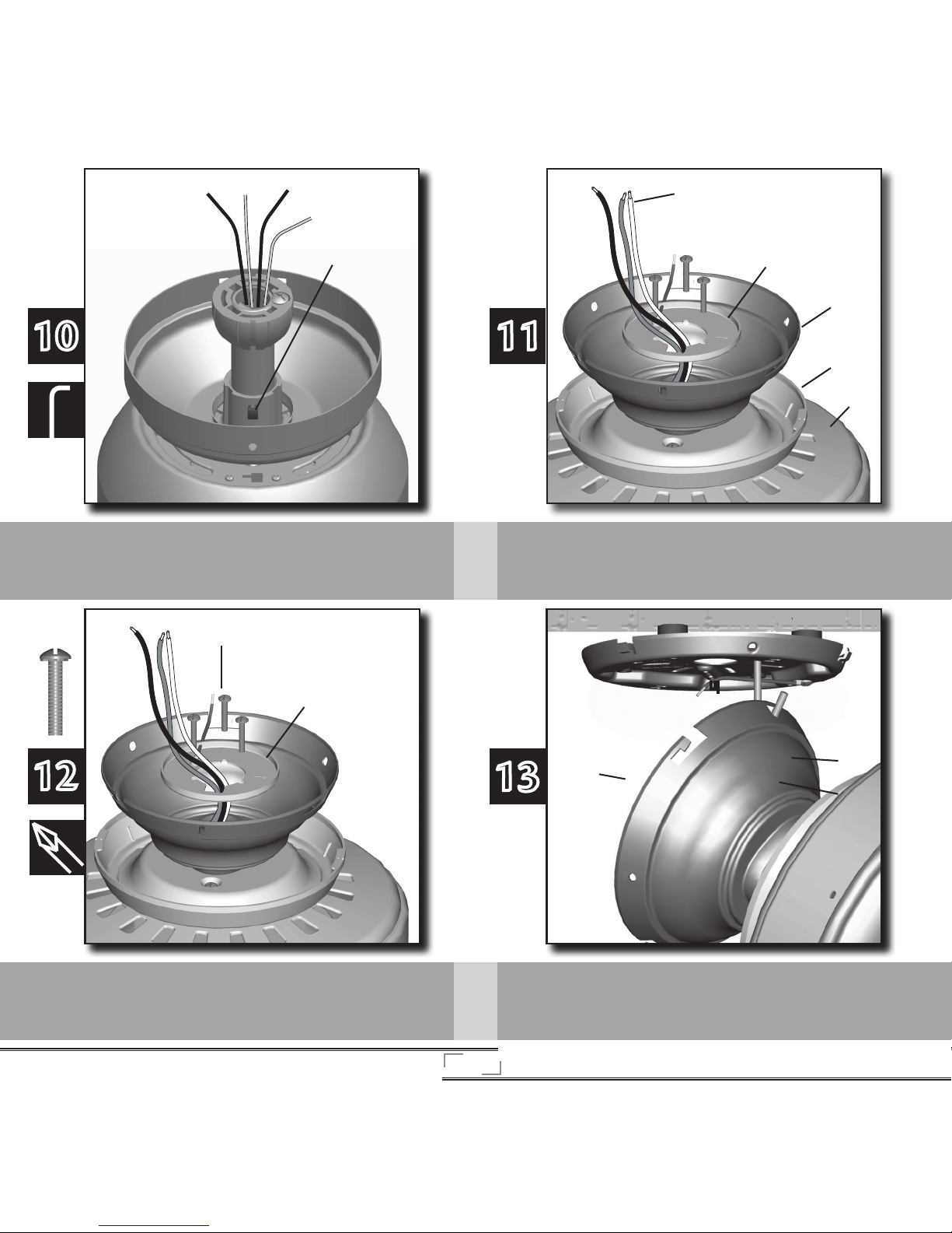
Securely tighten the pipe setscrew [a]. Proceed to step 18.
10
For flush mounting:
Slide the canopy trim ring [a], canopy [b] and low profile washer
[c] onto the wires [d] from the fan motor [e].
11
[a]
[b]
[e]
[d]
[c]
13
Align the holes in the assembly washer [a] with the holes in the top
of the fan and secure with three assembly screws [b].
12
Raise the fan and place the hook [a] on the ceiling plate through the
U-shaped hole [b] in the rim.
[b]
[a]
[c]
[b]
[a]
[a]
Page 9
9
WARNING! To avoid possible electric shock, before wiring the fan, disconnect
power to the fan by turning o the circuit breakers to both the outlet box and its
associated wall switch location. If you cannot lock the circuit breakers in the o
position, securely fasten a prominent warning device, such as a tag, to the service
panel. All wiring must be in accordance with national and local electrical codes. If
you are unfamiliar with wiring, you should use a qualied electrician.
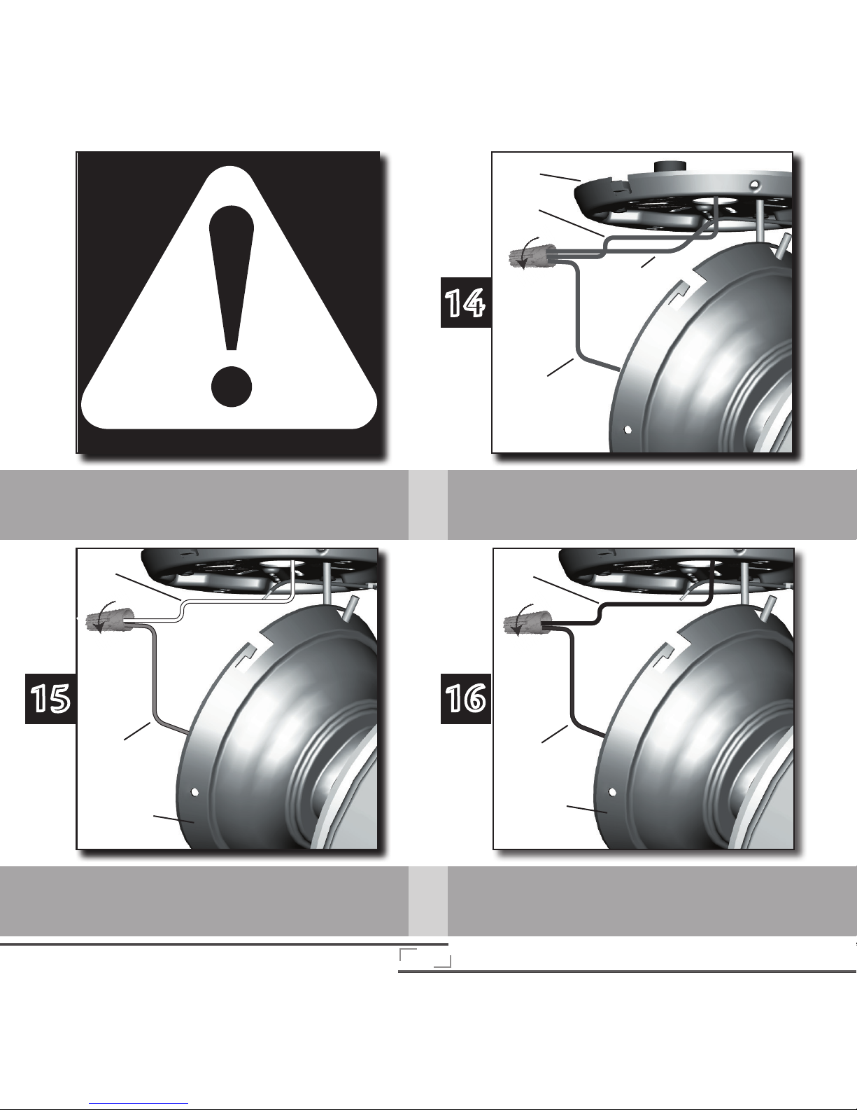
Connect the end of the earth wire [a] (green) from the ceiling plate
[b] and the earth wire [c] from the ceiling to the green wire [d]
from the ball. Secure by twisting a wire nut clockwise onto the bare
ends of the wires until tight.
14
[b]
[c]
[d]
[a]
Connect the end of the blue wire [a] from the fan [b] to the white
wire [c] from the ceiling by twisting a wire nut onto the bare wires
clockwise until tight.
15
[b]
[c]
[a]
Connect the end of the brown wire [a] from the fan [b] to the
black wire [c] from the ceiling by twisting a wire nut onto the bare
wires clockwise until tight.
16
[b]
[c]
[a]
Page 10
10
[a]
[b]
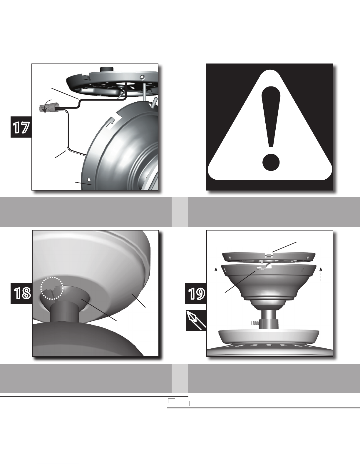
If you have a separate switch for the light, connect that wire [a] to
the black and white wire [b] from the fan motor [c] by twisting the
ends together and securing with a wire nut.
If not, connect the black and white wire from the fan to the black
wires from the previous step.
17
[c]
[a]
[b]
WARNING! Be sure no bare wire or wire strands are visible after making
connections. Failure to complete the following steps carefully could
result in the fan falling.
[b]
[a]
18
If you are low profile mounting, skip this step. If you are standard or
angle mounting, rotate the pipe ball [a] in the canopy [b] so that
the tab on the canopy [b] sits in the groove of the pipe ball [a].
Align the slots in the canopy [a] with the tabs on the ceiling plate
[b].
19
Page 11
11
[a]
[c]
[b]
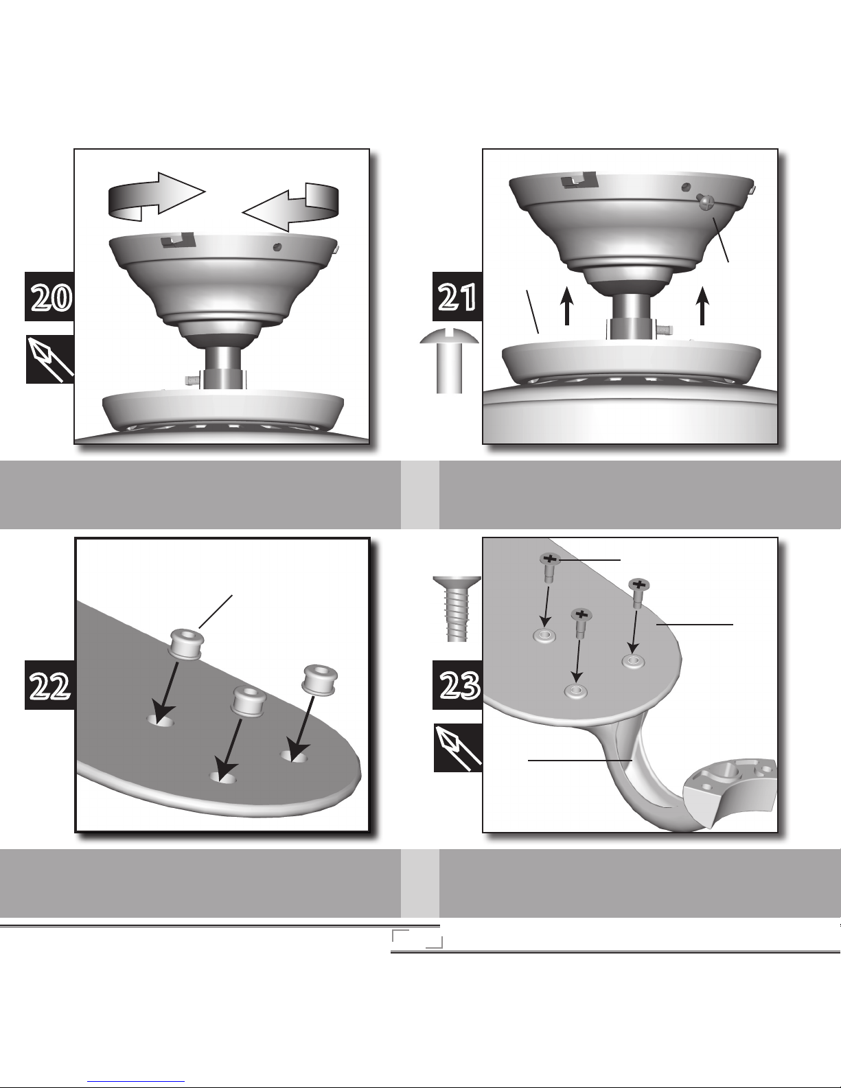
Raise the canopy over the ceiling plate. Rotate the canopy clockwise
until the tabs on the ceiling plate totally engage with the slots in the
canopy
Partially install the three canopy screws [a] into the canopy one at a
time. Once all three screws are in, tighten them.
Using both hands, push the canopy trim ring [b] up to the top of
the canopy. e canopy trim ring will snap and lock into place.
20
21
[a]
[b]
[a]
22
23
If your fan includes grommets [a], place them in the fan blade holes
by hand.
Attach the fan blade [a] to the blade iron [b] using three blade
assembly screws [c]. Repeat for all blades. Securely tighten all
screws.
Page 12
12
24
25
26
27
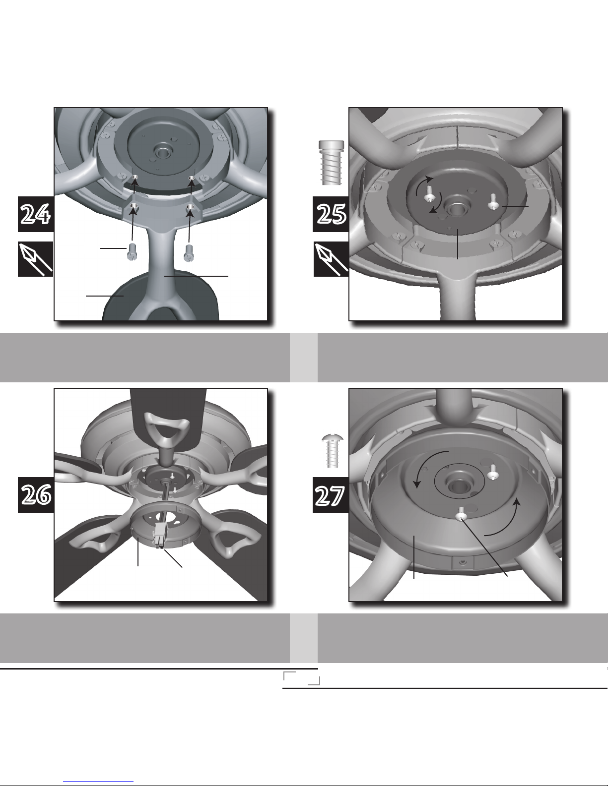
Partially thread two small assembly screws [a] into two of the three
outermost holes on the switch housing mounting plate [b].
Place the keyhole slots in the upper switch housing [a] over the
loosely threaded assembly screws [b] then rotate the switch
housing [a] counterclockwise until the screws are situated in the
narrow end of keyhole.
[a]
[c]
[b]
Loosely insert blade mounting screws [a] through the blade iron
[b] into the fan until all fan blades [c] are spaced and attached.
Securely tighten all screws.
[a]
[b]
Pull the upper plug connector [a] through the center of the upper
switch housing [b].
[a]
[b]
[a]
[b]
Page 13
13
28
29
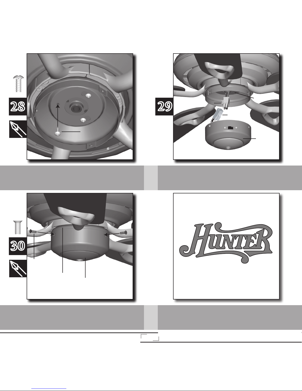
Install the remaining small assembly screw [a] into the third hole
and tighten all three securely.
Attach the plug connector [a] from the motor housing [b] to the
plug connector [c] on the lower switch housing [d].
30
Place the lower switch housing assembly [a] over the upper switch
housing [b] then align the holes of both housings and secure with
three side screws [c].
[a]
[a]
[b]
[c]
[d]
[c]
[a]
[b]
Page 14
14
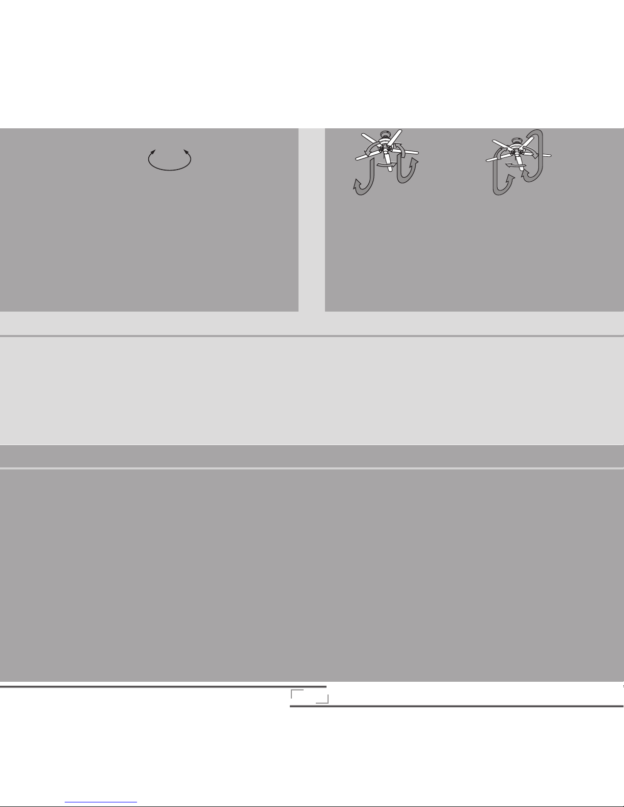
Ceiling fans work in two directions: downdraft (counterclockwise rotation)
and updraft (clockwise rotation). Downdraft creates a direct breeze and
maximum cooling eect. Updraft creates a more indirect airow. Many
consumers prefer the indirect airflow as a night time setting in summer
or winter. In winter, using the updraft setting will distribute the warmer
air trapped near the ceiling and distribute that air without causing a draft.
To change the direction of air flow, turn the fan off and let it come to a
complete stop. Slide the reversing switch to the opposite position. Restart
the fan.
Reversing
• Turn on the electrical power to the fan.
• e fna pull chain controls powe rto the fan. e chain has four settings
in sequence: High, Medium, Low, and O.
• To change the direction of the airow, turn the fan o and wait for it to
come to a complete stop. Slide the reversing switch on the fan to the
opposite position then restart the fan.
Cleaning and Maintenance
Cleaning and Maintenance
Caring for nishes:
For cleaning, a soft brush or lint-free cloth should be used to prevent scratching the nish. A vacuum cleaner brush nozzle can remove heavier dust. Surface
smudges or an accumulation of dirt and dust can be easily removed by using a mild detergent and a slightly dampened cloth. An artistic agent may be used,
but never use abrasive cleaning agents as they will damage the finish.
Caring for blades:
Wood finish blades should be cleaned with a furniture polish cloth. Occasionally, a light coat of furniture polish may be applied for added protection and
beauty. Painted and high-gloss blades may be cleaned in the same manner as the fan finish.
If you need parts or service assistance contact your Hunter Fan retailer or visit out website at http://www.hunterfanglobal.com.
Troubleshooting
Problem: Excessive wobbling.
Solution:
• Use balancing kit included with fan.
• Tighten all screws.
• Turn power o, support fan very carefully and check that the ball is
properly seated.
Problem: Nothing happens; light does not come on.
Solution:
• Restore power to the fan.
• Make sure bulbs are properly installed and lament is not blown.
• Set light kit to ON.
• Make sure plug connectors are properly connected and locked together.
• Check light power lead at the ceiling.
Troubleshooting
Problem: Nothing happens; fan does not move.
Solution:
• Turn power on, replace fuse, or reset breaker.
• Loosen canopy, check all wiring connections.
• Push reversing switch rmly left or right.
Problem: Noisy operation.
Solution:
• Tighten blade assembly and blade mounting screws until snug.
• Replace all blades.
Problem: Glass rattles.
Solution:
• Make sure all three tabs are properly engaged.
If you have tried these troubleshooting solutions and still have
trouble, visit our website at http://www.hunterfanglobal.com.
Page 15

44202 07/08/2010
 Loading...