

Hunter 44155C Owner's Manual
Set & $aveSet & $aveSet & $ave
Programmable Thermostat
Form# 42708-01
20120210
©2012 Hunter Fan Co.
installation and
operation manual
Models
44155
English
c
44157
1

2

TABLE OF CONTENTS
Important Information....................................... 5
Tools ................................................................ 6
Uninstalling the Existing Unit ........................... 7
Installing the Thermostat ............................... 12
Installing the Wall Plate ................................. 13
Connecting the Wires .................................... 16
Attaching the Thermostat .............................. 18
Settings ......................................................... 22
Methods of Operation .................................... 27
Manual Operation .......................................... 28
Default Programs .......................................... 32
Creating Custom Programs ........................... 34
Icons and Features ....................................... 38
Troubleshooting ............................................. 49
3

Set & Save
Set & Save
Programmable Thermostat
Programmable Thermostat
Model 44155C
Model 44155C
Congratulations!
Thank you for choosing a Hunter programmable
thermostat. Your new Hunter thermostat will
provide years of reliable service and year-round
energy savings.
Please read this manual before beginning
installation and save this booklet for complete
operation instructions.
4

IMPORTANT INFORMATION
This thermostat is designed to work on the following
heating and cooling systems:
Gas – Standing Pilot
Gas – Electronic Ignition
Gas – Fired Boilers
Gas – Milivolt Systems
Oil – Fired Boilers
Oil – Fired Furnace
Electric Furnace
Electric Air Conditioning
Single Stage Heat Pump - No auxilary
This thermostat is not designed for multi-stage heat
pump systems or 110/220 V baseboard heating
systems.
If you are unsure what kind of heating and cooling
system you have, please contact a qualied HVAC
Technician for assistance.
5

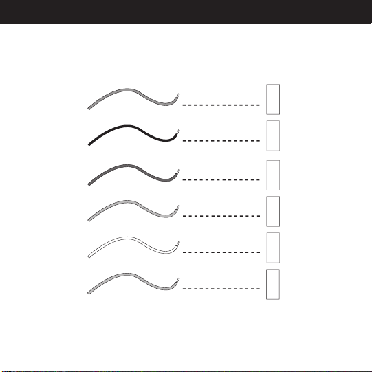
TOOLS
This thermostat includes two #8 slotted screws
and two wall anchors for mounting.
To install your new thermostat, you will need the
following supplies:
....................................................................................
Small Phillips-head screwdriver
Flat-head screwdriver
....................................................................................
Hammer
....................................................................................
Electric drill and 3/16” bit
....................................................................................
Two 1.5 Volt (AA) size alkaline batteries
....................................................................................
6

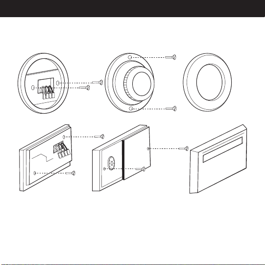
UNINSTALLING THE EXISTING UNIT
NOTICE! Do not disconnect the
wires from the existing thermostat
before reading these instructions.
The wires must be labeled prior
to removal to ensure proper
reconnection.
7
W
G
Y
RC
W
G
Y
RC
8

1. Turn the system power OFF from the existing
thermostat. Turn the power to the HVAC
system OFF at the main power panel or at
the furnace.
2. Remove the existing thermostat cover to
access the wires from the wall.
(Some thermostats may have multiple covers, screws
or other locking devices that must be removed or
disengaged.)
3. Locate, but do not disconnect the wires.
(If wires are not visible, they may be connected to the
back of the wall plate. Some models may have doors
that open to expose the wires and mounting screws.)
9
if your existing
thermostat is marked...
label the wire
with this sticker:
G / F
G
G
W / H / B
W/B
W/B
Y / C* / M / O
Y/0
Y/0
RC / VC
RC
RC
RH / R / VR / 4
RH
RH
24 Volt
24 Volt cool
air conditioning
compressor
heating
fan
Y1
Y1
Y1
heat pump
compressor
10

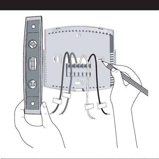
4. Using the provided stickers, label each wire
according to the chart.
• If the terminals are not labeled, contact a qualied
HVAC technician.
•Note: Wire colors do not always comply with
standards, so wire color should be ignored. Refer
to the existing terminal designation for proper
identication.
• *If wires marked Y & C are both present, C may
be a Common wire and should not be used. If you
have a wire marked C, do not connect it to any
terminal. This wire is used only for non-battery
powered thermostats.
5. Do not let the wires slip back into the
wall during disconnection. You may want
to secure the wires to the wall as you
disconnect them. After all wires are labeled,
disconnect each wire and remove the
existing wall plate.
11
INSTALLING THE THERMOSTAT
Y
G
W
RC
12

INSTALLING THE WALL PLATE
1. Remove the wall plate from the new
thermostat by pressing the release tab on the
bottom of the thermostat.
2. Position the new wall plate on the wall and
pull the labeled wires through the opening.
3. If the existing holes do not match those
on the Hunter wall plate, or if there are no
existing holes, visually level the wall plate
and mark the wall for two holes.
13
Y
G
W
RC
14

4. Remove the wall plate and drill two 3/16”
holes where marked.
5. Tap the plastic anchors into the holes until
they are ush with the wall.
6. Reposition the wall plate on the wall, pulling
the wires through the opening. Insert the
mounting screws through the wall plate and
into the anchors. Verify that the wall plate
is visually level and securely tighten both
screws.
15
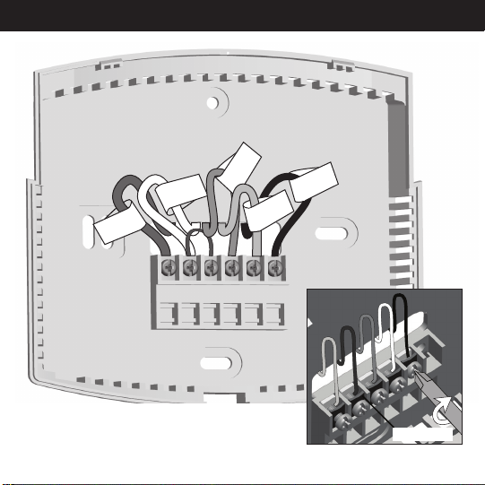
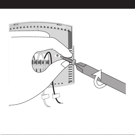
CONNECTING THE WIRES
Y/0
RC
G
Y1
W/B
G
RCRH
Y/0
16
W/B
Y1
Terminal Shield
 Loading...