How it Works
Log In / Sign Up
Buy Points
How it Works
FAQ
Contact Us
Questions and Suggestions
Users
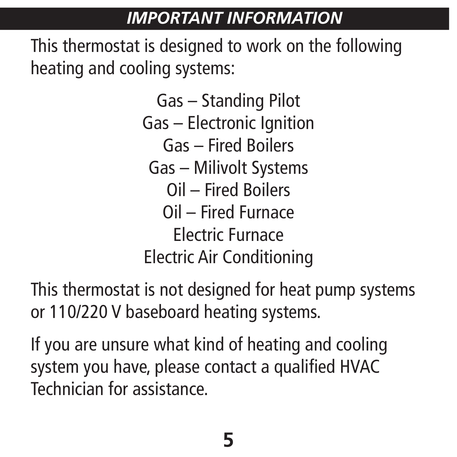
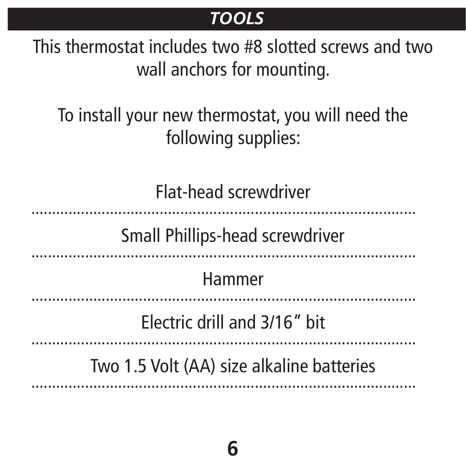
Hunter
Loading...
#
511
37090
37125
37200
37201
37202
37203
37204
37205
2
37207
37222
37225
37232
37250
37251
37252
37255
2
37300
37302
37350
37352
37407
37710
37711
37750
37755
37785
38257
40007
40080
40120
2
40135
2
40170
2
40352
42203
42204
42223
42227
42345
42995B
42999B
43004
43005
43007
43018
43057
43058
43103
43855
44100
44100A
44110
2
44132
44150
44155C
2
44260
2
44377
44660
44668
44758
44760
47200
50780
50783
50976
50977
51039
51040
51042
51059
51060
51061
51080
51081
51082
51221
51427
52105
52106
52107
51023 42
51026 44
52005 52
52007 52
52019 48
52022 36
52044 52
52063 48
52096 52
52099 52
52100 52
52112 52
53006 52
53014 52
53015 52
53022 52
53026 52
53032 52
53038 52
2
53061 52
Loading...
Loading...
Nothing found
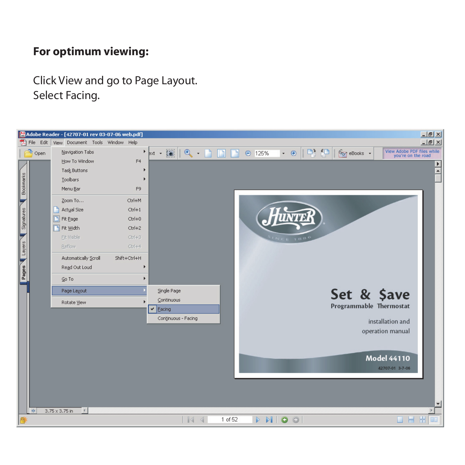
44110
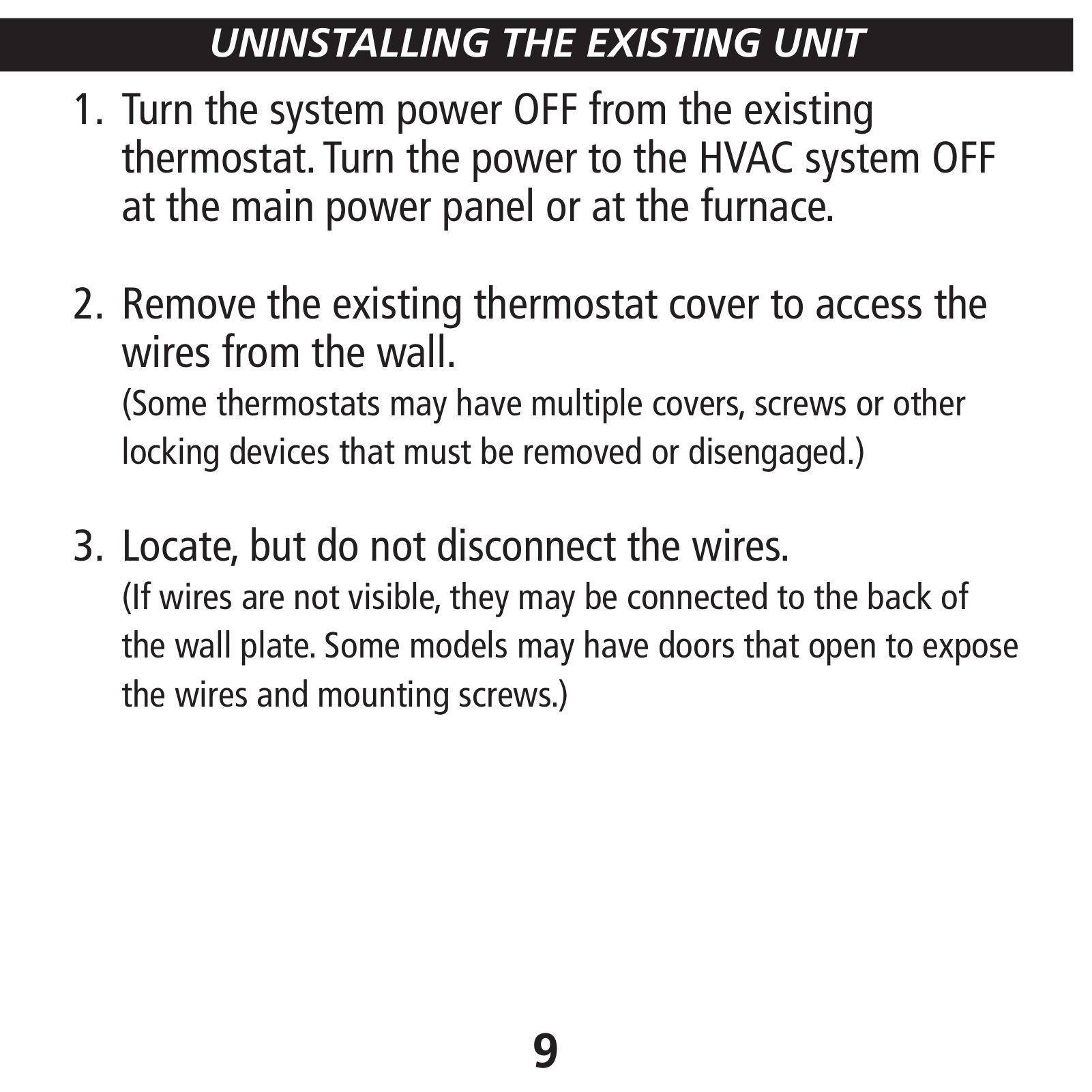
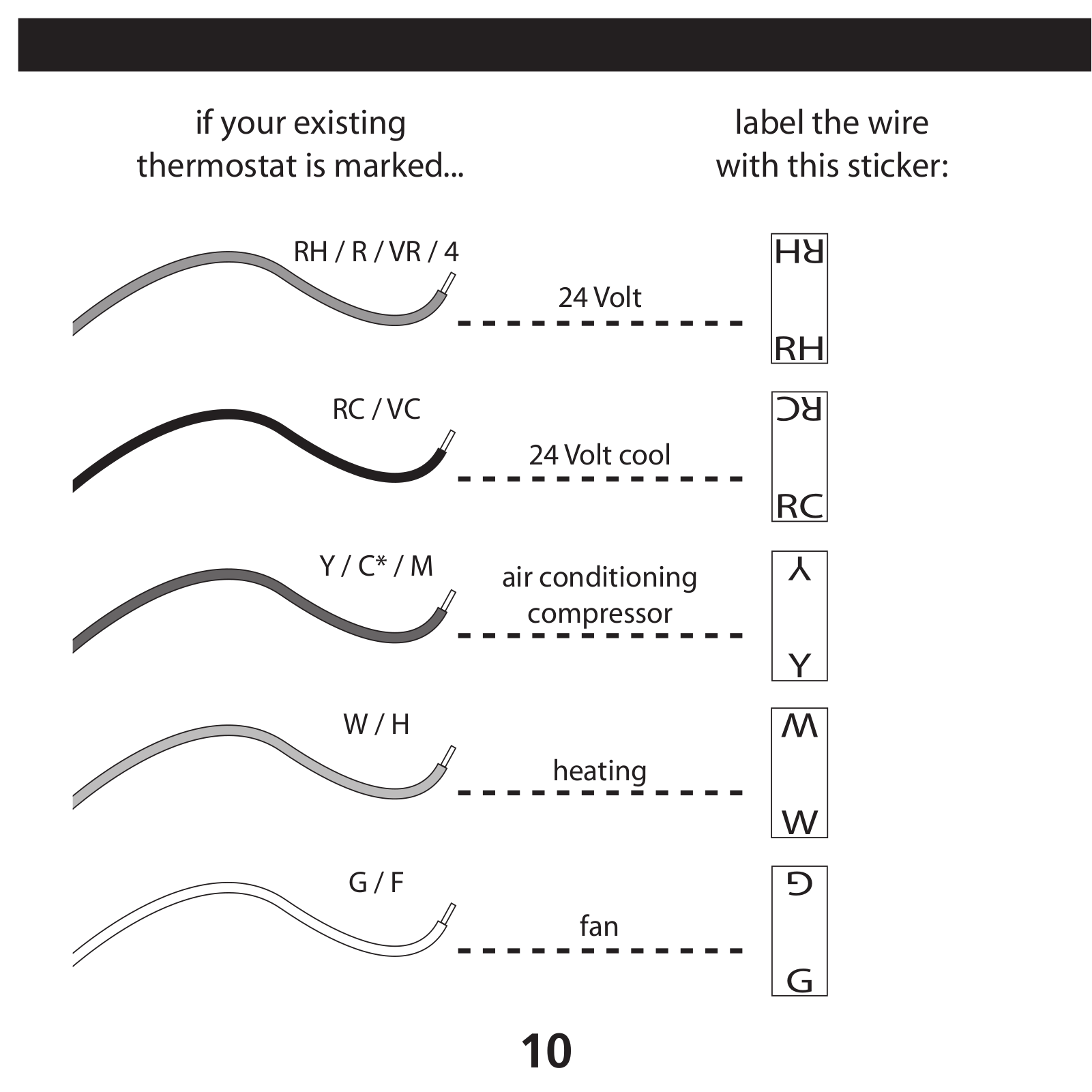
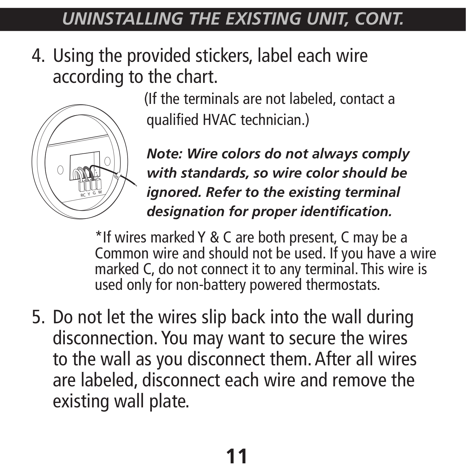
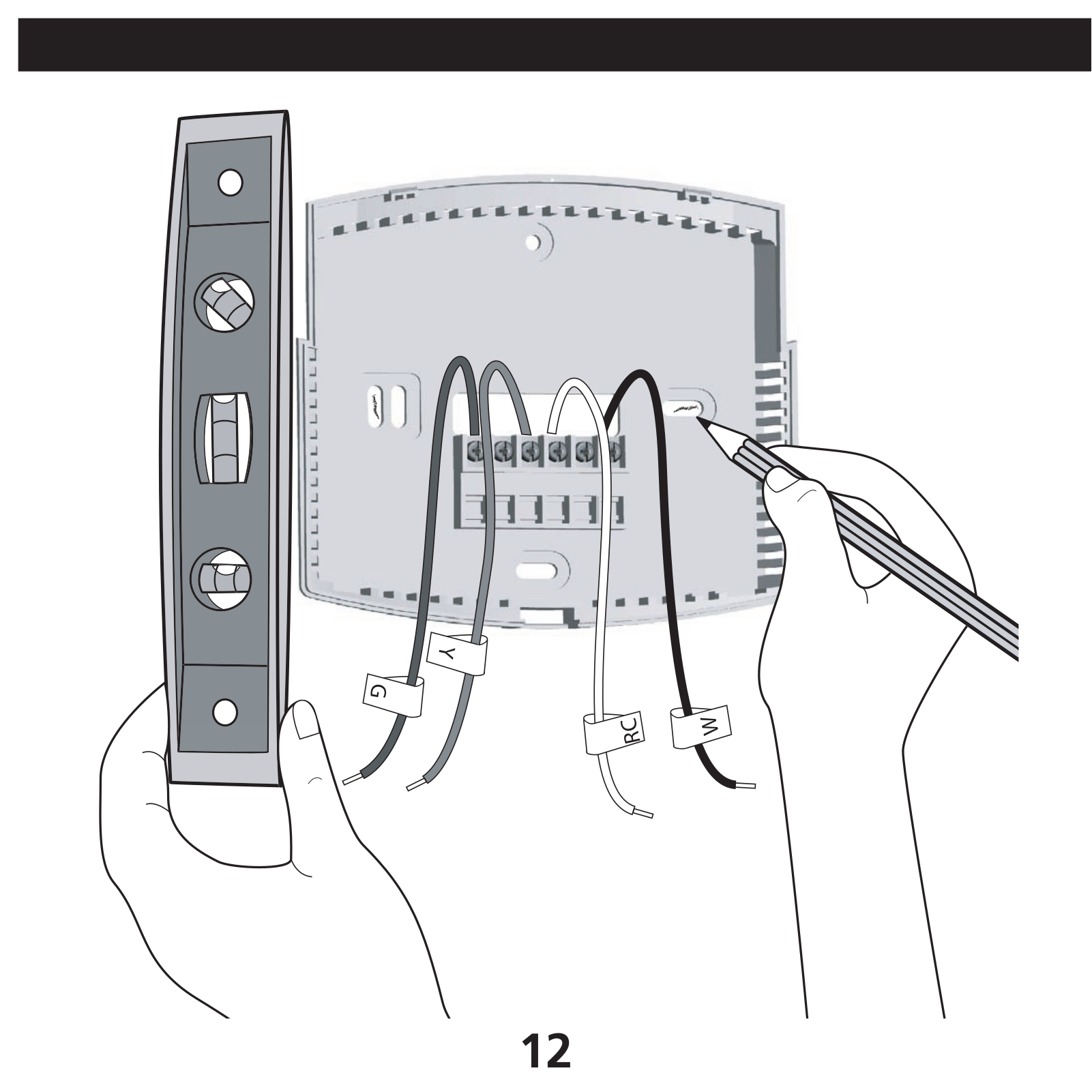
Owner's Manual
7 pgs
306.98 Kb
0
Owner's Manual
54 pgs
1.7 Mb
0
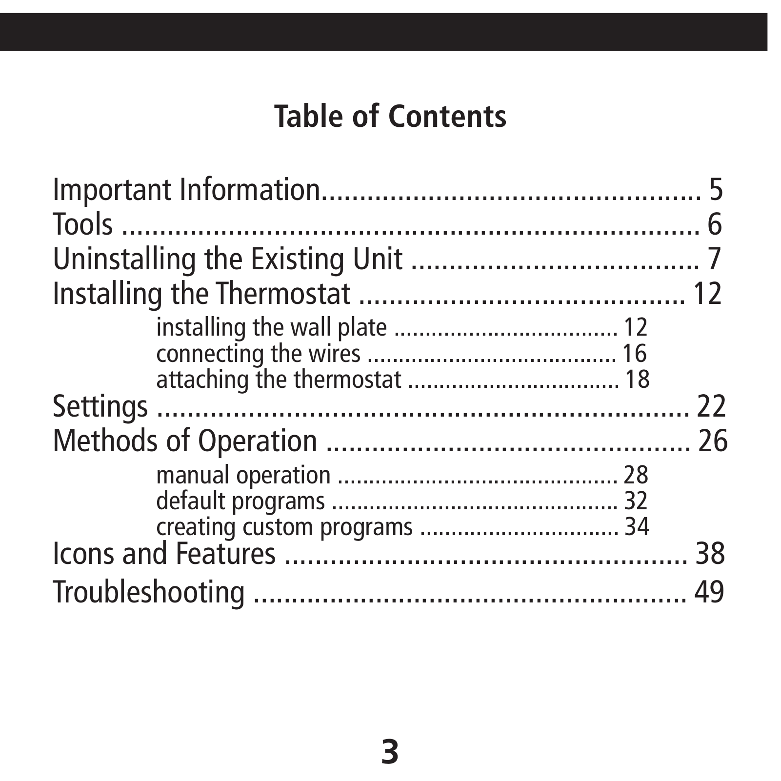
Table of contents
Loading...
Hunter 44110 Owner's Manual
...
Hunter Owner's Manual
Download
Specifications and Main Features
Frequently Asked Questions
User Manual
Download
Loading...
+
37
hidden pages
Unhide
You need points to download manuals.
1 point = 1 manual.
You can buy points or you can get point for every manual you upload.
Buy points
Upload your manuals
 Loading...