

Hunter 43855 Owner's Manual

Hunter Fan
2500 Frisco Ave.
Memphis, TN 38114
888-830 -1326
www.hunterfan .com

installation and
operation manual
Touchscreen Programmable ermostat
Model 44860
2 Stage Heat/2 Stage Cool

2
TABLE OF CONTENTS
IMPORTANT INFORMATION ......................................4
INSTALLATION PROCEDURES ....................................4
GENERAL OPERATING INSTRUCTIONS .....................21
DATE & TIME SETTINGS ............................................22
SYSTEM SETTINGS MENU .........................................27
USER SETTINGS MENU ..............................................31
TEMPERATURE RANGE .............................................34
ENERGY STAR DEFAULT PROGRAMS ........................35
MANUAL OPERATION ...............................................36
PROGRAM OPERATION ............................................. 39
PROGRAM OVERRIDES ..............................................46
ADDITIONAL FEATURES ............................................56
CLEAN SCREEN ..........................................................56
CHANGE FILTER .........................................................60
ENERGY MONITOR FUNCTION ..................................64
TROUBLESHOOTING ..................................................68
WIRING DIAGRAMS ..................................................72
440 02- 01 r06 0607

3
Touchscreen Programmable ermostat
Model 44860
2 Stage Heat/2 Stage Cool
Congratulations!
Thank you for choosing a Hunter programmable
thermostat. Your new Hunter thermostat will
provide years of reliable service and year-round
energy savings.
Please read this manual before beginning
installation and save this booklet for complete
operating instructions.
440 02- 01 r06 0607

4
IMPORTANT INFORMATION
This thermostat is designed to work on the following heating and cooling systems:
Up to 2 Stage Heat/2 Stage Cool Millivolt Systems
Heat Only or Cool Only Systems 2-wire Hydronic Systems
Single and Multi-Stage Heat Pumps AC or Hard-wired
Gas, Electric or Oil Systems
This thermostat is not designed for use with 110V/220 V systems. If you are unsure of
what kind of heating and cooling system you have, please contact a qualified HVAC
Technician for assistance.
INSTALLATION PROCEDURES
TOOLS
This thermostat includes two #8 slotted screws and two wall anchors for mounting.
To install your new thermostat, you will need the following supplies:
Flat-head screwdriver, Small Phillips-head screwdriver, Hammer
Electric drill and 3/16” bit, Three 1.5 Volt (AA) size alkaline batteries
440 02- 01 r06 0607
5
Y
R
C
G
W
w
Y
R
C
G
W
NOTICE OF CAUTION! DO NOT disconnect
the wires from the existing thermostat
before reading these instructions. The
wires must be labeled prior to removal
to ensure proper connection.
440 02- 01 r06 0607
6
Y
RC
G
W
Y
RC
G
W
440 02- 01 r06 0607

7
UNINSTALLING THE EXISTING UNIT
1. Turn the system power OFF at the existing thermostat. Turn the power to the
HVAC system OFF at the main power panel or at the furnace.
(Failure to turn off the power to the existing thermostat before removal could damage your
system.)
2. Remove the existing thermostat cover to access the wires from the wall. (Some
thermostats may have multiple covers, screws or other locking devices that must
be removed or disengaged.)
3. Locate, but do not disconnect the wires.
(If wires are not visible, they may be connected to the back of the wall plate. Some models may
have doors that open to expose the wires and mounting screws.)
4. Do not let the wires slip back into the wall during disconnection. You may want to
secure the wires to the wall as you disconnect them. After all wires are labeled,
disconnect each wire and remove the existing wall plate. (Any unused wires
should be capped with an approved electrical connector, such as electrical tape.)
440 02- 01 r06 0607

8
440 02- 01 r06 0607

9
5. Using the provided stickers, label each wire according to the chart.
If the terminals are not labeled, contact a qualified HVAC technician.
NOTE: Wire colors do not always comply with standards; therefore, wire color should be ignored.
Refer to the existing terminal designation for proper identification.
If wires marked “Y” or “C” are both present, “C” may be a Common wire and provides 24 VAC
power to the unit. Connecting it greatly extends battery life. If there is no "C" wire, the thermostat
will run on battery power.
440 02- 01 r06 0607
10
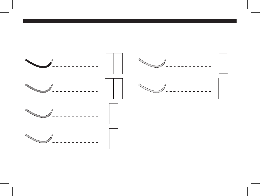
if your existing
thermostat is marked:
label the wire
with this sticker:
RH
RH
RH
Heating Transformer
Power Supply
Y1 / Y2
Cooling Stage 1 or 2
W1 / W2
Heating Stage 1 or 2
C
C
C
24 VAC Common
(if available)
CONVENTIONAL HVAC SYSTEMS
G
G
G
Fan
R / RC
R/RC
R/RC
Cooling Transformer
Power Supply
if your existing
thermostat is marked:
label the wire
with this sticker:
W1 W2
W2 W1
Y1 Y2
Y2 Y1
See pages 72-73 for a complete wiring diagram.
440 02- 01 r06 0607
11
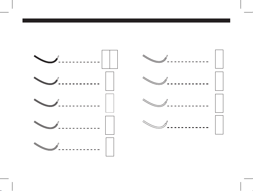
if your existing
thermostat is marked:
label the wire
with this sticker:
R / RC
R/RC
R/RC
24 VAC Power Supply
Y1 / Y2
Compressor Stage 1 or 2
W2
W2
W2
Auxilliary Heat
E
E
E
Emergency Heat
C
C
C
24 VAC Common
HEAT PUMP SYSTEMS
O
O
O
Cool Mode Powered
Reverse Valve
B
B
B
Heat Mode Powered
Reverse Valve
G
G
G
Fan
L
L
L
System Monitor
if your existing
thermostat is marked:
label the wire
with this sticker:
Y1 Y2
Y2 Y1
Y1 Y2
See pages 74 for a complete wiring diagram.
440 02- 01 r06 0607
12
Y1 Y2 W3 RH
RCR
G
W2
B W1
OE C
W
G
Y
RC
L
440 02- 01 r06 0607

13
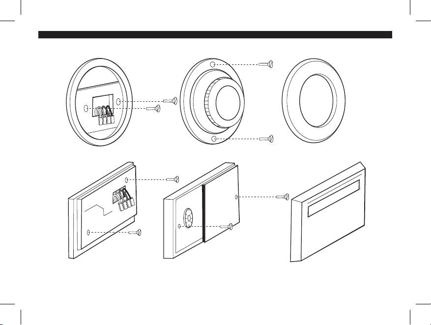
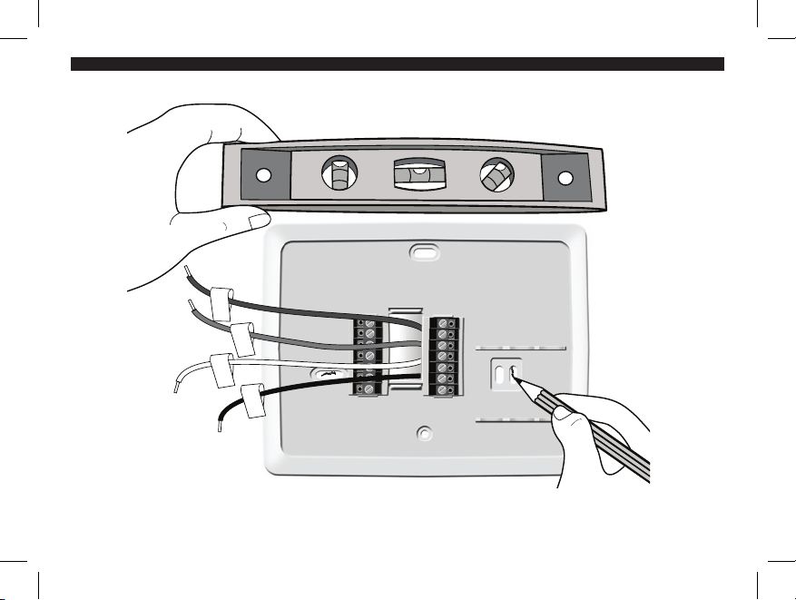
MOUNTING THE WALL PLATE
1. Remove the wall plate from the Hunter thermostat by gently pulling the wall plate
from the back of the thermostat.
2. Position the new wall plate on the wall horizontally and pull the labeled wires
through the opening.
3. If the existing holes do not match those on the Hunter thermostat wall plate or, if
there are no existing holes, visually level the wall plate and mark the wall for two
holes.
440 02- 01 r06 0607
14
W
G
Y
RC
440 02- 01 r06 0607

15
4. Remove the wall plate from the wall and drill two 3/16” holes where marked.
5. Tap the plastic anchors into the holes until they are flush with the wall.
6. Reposition the wall plate on the wall, pulling the wires through the wall plate
opening. Insert the mounting screws through the wall plate and into the anchors.
Verify that the wall plate is level. Securely tighten both screws.
440 02- 01 r06 0607
16
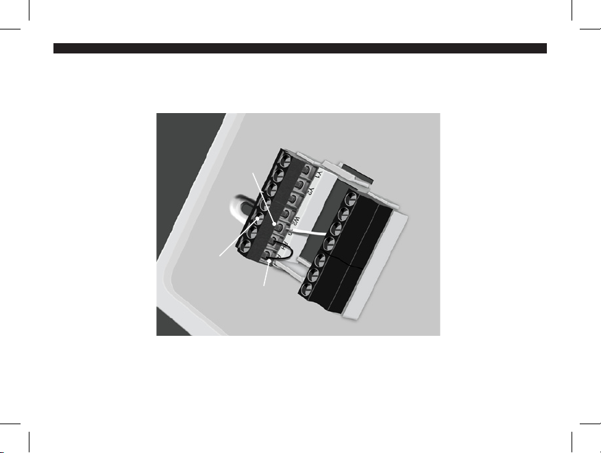
Terminal
Shield
Terminal
Screw
Jumper
Wire
440 02- 01 r06 0607

17
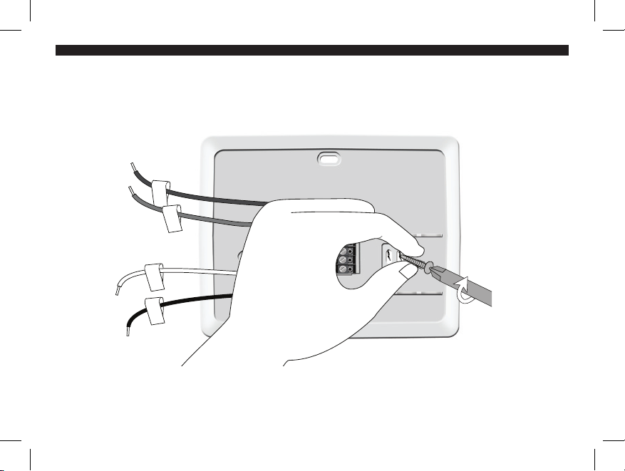
CONNECTING THE WIRES
1. Loosen, but do not remove the terminal screws.
NOTE: A jumper wire is provided, connecting the RH and RC terminals for systems that do not have
both an RH and RC wire. If you have both an RH and RC wire, remove this jumper; otherwise, leave
the jumper in place.
2. Complete wiring diagrams for Conventional HVAC Systems and Heat Pump
Systems are provided on pages 72-74. Match and connect the wires from the wall
to the terminals as shown. Insert wires behind the black terminal shield. Tighten
each screw after the connection is made.
3. Wrap the ends of any extra wires individually in electrical tape and carefully push
them into the wall. Push any excess wire length back into the wall to prevent
interference.
440 02- 01 r06 0607
18
440 02- 01 r06 0607

19
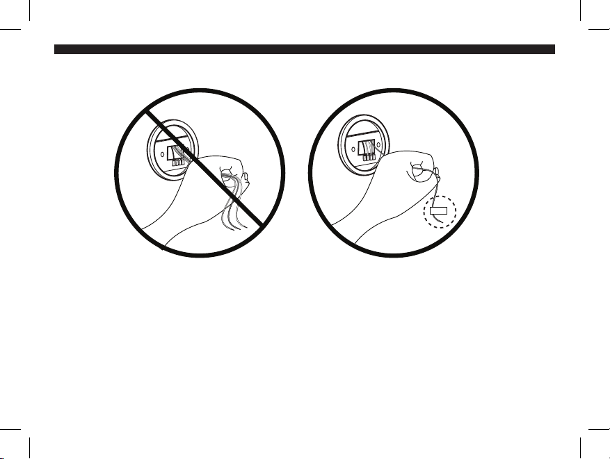
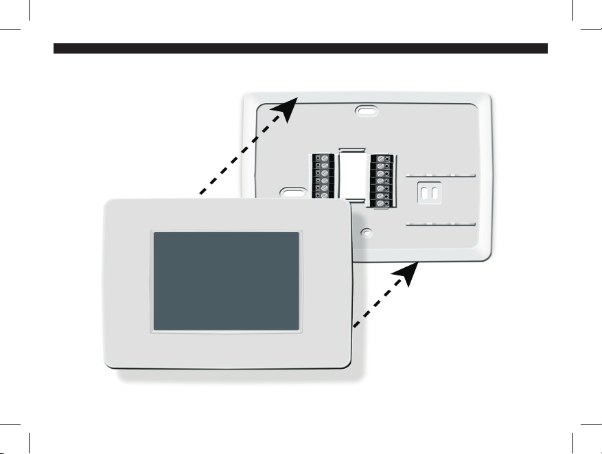
ATTACHING THE THERMOSTAT
1. Insert three AA alkaline batteries into the back of the thermostat.
2. Place the thermostat over the wall plate, aligning it over the terminal and battery
openings. Press the thermostat to the wall plate and it will snap into place.
NOTE: Do not force the thermostat onto the wall plate as this may damage the terminal pins. If the
thermostat does not snap into place easily, the unit may not work.
3. Restore power at the electrical panel and/or furnace.
440 02- 01 r06 0607
20
MA Y 1 7 20 0 6
TH U RS D A Y
440 02- 01 r06 0607

21
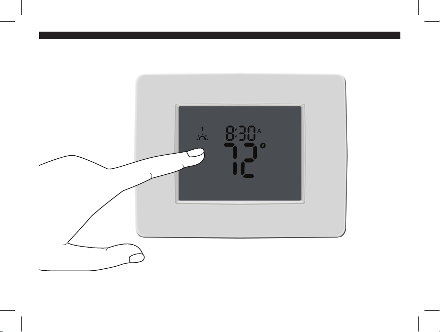
GENERAL OPERATING INSTRUCTIONS
Your new Hunter thermostat is easy to program and use. The front of the thermostat
is a touch screen that responds to the pressure of a finger.
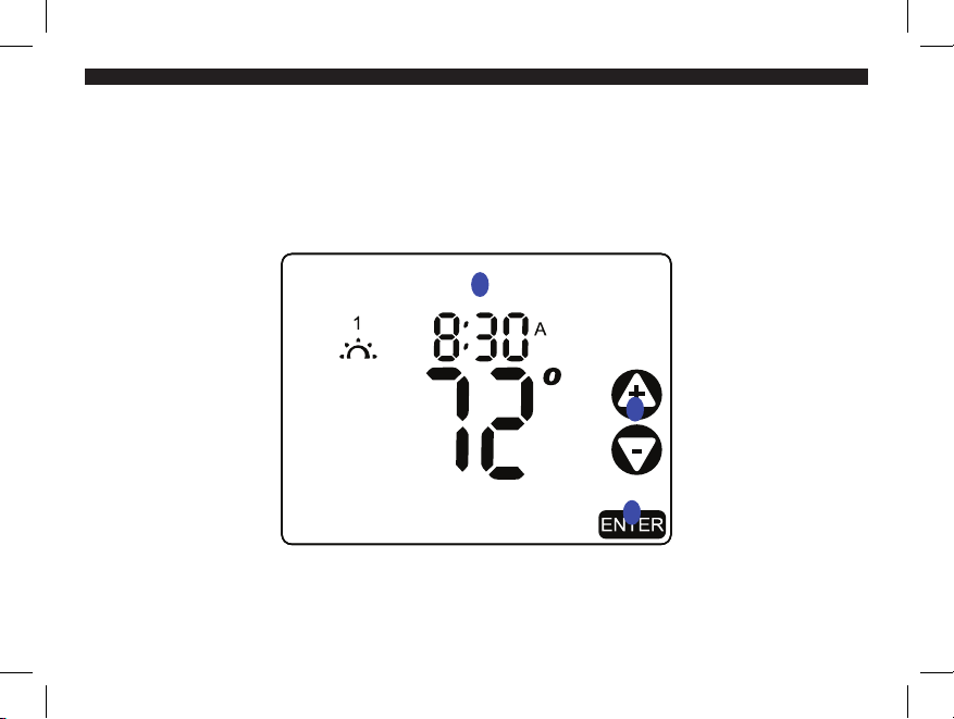
You can program the thermostat to automatically readjust the temperature and
airflow to settings that you choose or you can use the pre-programmed default
settings. You can also operate the thermostat manually.
440 02- 01 r06 0607
22
DATE & TIME SETTINGS
DATE, MONTH, YEAR
MAY 1 7 2 0 0 6
THURS D A Y
1
2
3
440 02- 01 r06 0607
 Loading...