

Page 1

.( .;i I
SINCE
« «.III »♦
Set In Save II Plus
1 8 « & PROGRAMMABLE THERMOSTAT
^ '• W» rfMf»*# *-rFf fM
.v'Ti“r~T^.“
Owner's Manual
Model 42223
Page 2

Table of Contents
Congratulationsi
Welcome to' the Hunter energy saving family of
quality products.
Your Hunter Programmable Thermostat allows you to
find your maximum comfort level using the least
amount of fuel. Through srnart programming, this
thermostat should pay for itself during Its first Season
of use.
Thank you for buying Hunter products!
Hunter Consumer Service Hotline
Weekdays 8 AM to 6 PM Central Standard Time
901-746-9222
Features
Installation
Setting Clock/Programming
Personal Program Schedule
Manual Override
Temperature Span
Energy Monitor
Energy Usage Chart '
Trouble Shooting Guide
Wiring Diagrams
6
a
14
18
29
31
31
34
36
38
Page 3

Read This Before Installing Thermostat
4-5
IMPORTANT
Read the entire installation section of this
Owner’s Manual thoroughly before you
I
begin to install or operate your Hunter
Thermostat
• Remove the mylar labei from the display
window.
INSTALUTION
All installation is normally performed at
your thermostat.
2
PROGRAMMING
You can practice programming before
installing your thermostat by inserting and
3
connecting the batteries as shown on page 13,
can be restarted- This feature will prevent
damage to your air conditioner compressor
caused by rapid cycling. It does not provide a
delay when there are power outages,
TEMPERATURE RANGE
Your thermostat can be programmed
6
between 40°F and 90°F. However, it will
display room temperatures from 32°F to
POWER FAILURE
Whenever the main power is Interrupted
or fails, the battery power retains the
7
programs and current time-
and following the instructions on page 14. Thiscan be done while you relax in your favorite
chair and is a very good way to familiarize
yourself with all the functions of your Hunter
Thermostat.
OPERATION
Your Hunter Therniostat is designed to
operate with most gas, oil, electric or
4
forced hot water heating and air conditioning
systems. These have 24-voit or millivolt
controls and represent most central heating
and air conditioning units in use In the United
States. ■
This Hunter Thermostat will not control multi
stage heating or cooling systems.
COMPRESSOR PROTECTION
- The thermostat provides a 4-minute delay
after shutting off the compressor before it’
5
BATTERY WARNING
When the batteries are low, “LOW ВАТТ”
indicator on the display will flash. When
8
this happens, install new batteries {do not use
old batteries) as soon as possible. The
battery should last one year.
CAUTION: The batteries are the only source
of power used to operate your system. If
you do not replace the batteries, the display
will dim and your heating and cooling
system will stop operation.
(f you have questions about the installation or
.programming of the Hunter Thermostat, call us
at 901-745-9222 from 8AM to 5PM Central
Standard Time.
Page 4
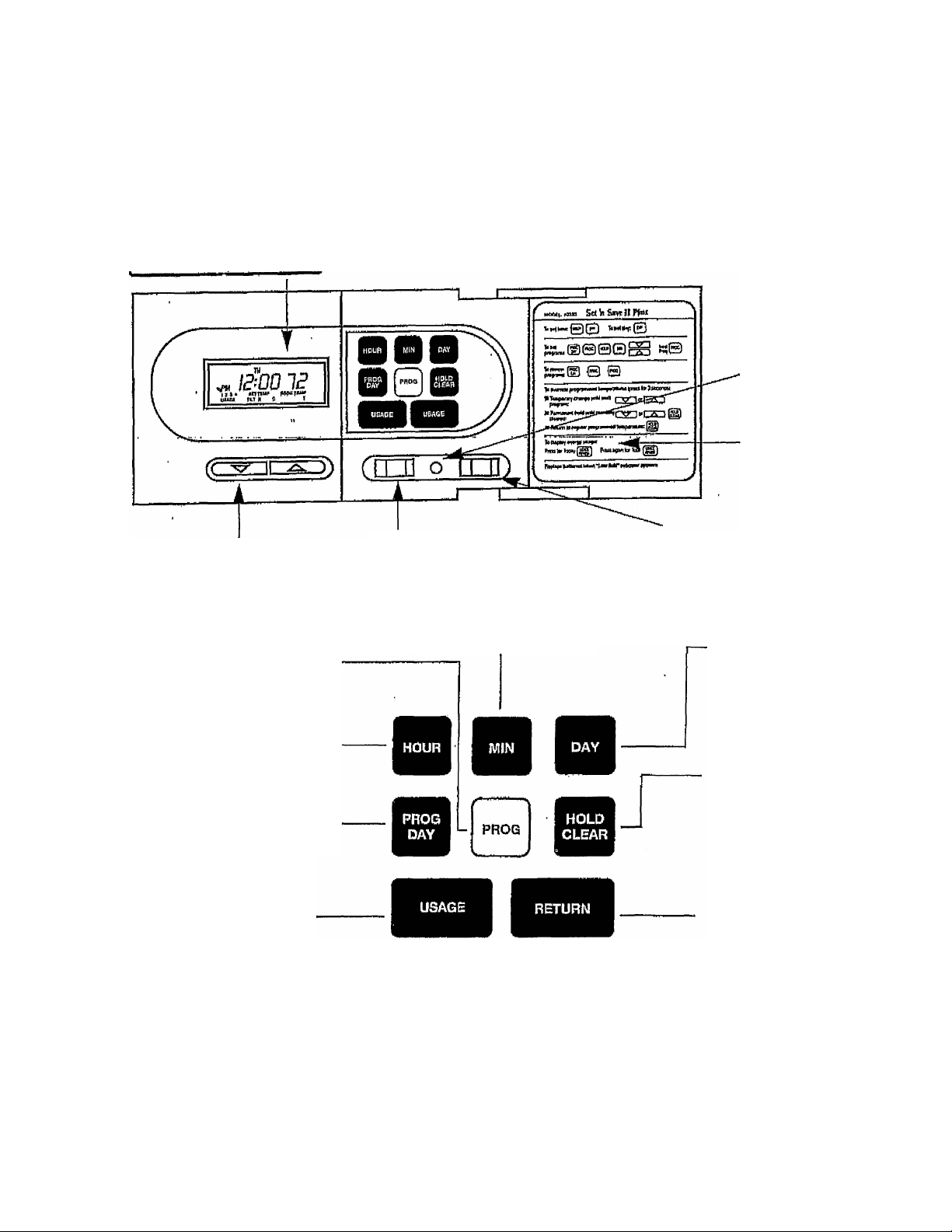
Features
6-7
mrvmmm&isu hold
IP^OO ÚÜ LOW
imfU^uu uu
USASE cool. HEAT 1 Я 3 4 -
Individual pushbuttons for raising
or lowering temperature settings.
DATI
Fqr reviewing or entering
Weekday and Weekend'
Program cycles.
Display shows time, day.
temperature, pM, program
number, hold and usage
indicator.
Manual switch for turning on
heating and cooling system.
For entering minute of day.
Simplified programming
instruotlons are provided on
inside of door cover for easy
reference.
Reset button for resetting
computer back to 12:00
A.M. and clearing all
programs.
Door label
Manual switch for automatic or
continuous fan operation.
For entering day of week.
For entering hour of day.
Picks the day/days for programs
Energy Monitor key recalls
energy usage today and total.
LCD shows energy usage in
hours and minutes.
Batteries keep programs
during power failure.
Provides permanent temperati
setting by overriding stored
programs or converts to manu
operation of thermostat Also,
clears manual override and
returns back to current prograr
Returns display to current
time and temperature. Also,
if held for 4 seconds, clears
manual override.
M Fingertip programming-easy
touch keyboard for entering
program and displaying time
and temperature setting and
energy usages.
Page 5

Installation
Your Hunter Thernnostat comes with two #6 slotted
screws and two anchors for mounting. To install your
unit, you should have the following tools and
materials:
■ Slotted Screwdriver
■ Electric drill and
3/16" bit
■ Hammer
V Three 1,6V (M size)
Alkaline batteries
Remove Old Thermostat
CAUTION: Do not remove any wiring from existing
thermostat before reading the instructions
carefully.
Wires must be labeled prior to removali.
<4 Turn your existing thermostat to OFF position.
I Turn off the power to the furnace at the main
power panel to avoid electrical shock.
j
Remove existing thermostat cover and
thermostat. Some thermostats will have screws
2
or other locking devices that must first be removed.
Once wall is exposed, look for wires.
If wires are not visjbie. they may be connected to the
back of wallpiate. Again, look for screws, tabs, etc.
Some models have doors that open to expose wires
and mounting screws (see Figure 1).
Each wire coming from the wall to the existing
thermostat is connected to a terminal point on
3
that thermostat. Each of these terminal points is
usually marked with a code letter as shown in Table
A, Before disconnecting any wires, apply the self
adhesive labels provided to the wire as shown In ‘
Table A. (For example, attach the label marked
W WHITE to the wire which goes to the W or H
terminal on your existing thermostat.)
TYPICAL. HOME THERMOSTATS
Your Hunter thermostat requires three 1.5 volt
batteries. You must replace the batteries
whenever the Low Battery indicator appears on
the display.
IGNORE THE COLOR OF T|-tE WIRES since these do
not always comply with the standard. The number of
wires in your system can be as few as two (for heat
only systems), as many as eight, or any number in
between, if you follow the labeling procedures
correctly, you don’t have to be concerned about how
many wires there are. There is often no terminal
marking on the existing thermostat of two wire, heat
onfy systems. Don't worry, dust connect either of the
wires to the "RED" terminal on your Hunter
thermostat. Then connect the other wire to the
"WHITE" terminal on your thermostat to complete the
circuit.
After labeling wires, disconnect them from the
4
existing thermostat terminals.
Remove existing wallpiate. To make sure wires
5
do not fall back Into wall opening, you may want
to tape them to the wall.
If hole In wall is larger than necessary for wires,
seal this hole up, so no hot or cold air can enter
6
the back of the thermostat from the wall. This air
could cause a false thermostat reading.
Cover
FIG.1
Wall Mounting Plate Thermostat
Cover
Page 6
,i e-
Installation
Wire Labeiin
If the code fetter on your then mark wire with
existing thermostat Is label shown
This table will help you
match the labels to the wires
so you can attach them to
your Hunter Thermostat
TABLE A
NOTE; 5-Wire Systerns
If your existing thermostat has separate wires going
to terminals marked “R” and “RH,” do this simple
test—momentarily turn the main power on. Lightly
scratch the two wires together, (Because this is only a
24V system, there Is no danger in performing this test)
RH, RC,
a M,VR, VC or 4
24 Volt
G or F
Fan
Y or 0 (See Note)
Air Conditionliig
WorH
Heating
10-11
and connect to thermostat
Terminal shown
RED
GREEN
YELLOW
WHITE
then be sure to turn the power off again. If you saw a
spark call 901 -745-9222 for further Information, If
there was no spark simply connect both these wires
to terminal marked "'RED” on your thermostat.
Connect only the wires that were connected to your
old thermostat to your new thermostat
NOTE: Do not connect a “Common” wire (sometimes labelled “C” to any terminal on this thermostat Tape up the
wire and do not use.
Mount Thermostat Wallplate
Snap open the wallplate from your Hunter thermostat
disconnect the battery and leadwire terminal connectors
Position wallplate on wal) and pull existing wires
through large opening. Then level for appearance.
Use any two of the many rectangular holes provided
on the wallplate for mounting. Mark holes for plastic
anchors provided if existing holes do not line up with
Hunter thermostat holes, (Figure 2)
Drill holes with 3/16" bit, and gently tap anchors Into
the holes until flush with wall.
Reposition wallplate to wall, pulling wires through
large opening, insert mounting screws provided into
wall anchor and tighten.
(Figure 2)
Page 7

Installation
Heating Systems Selector
The heating system seJector is a switch on the Printed Circuit Board, The switch is at "HG" position. Leave it In
this position if you have a gas furnace or an oil burner.
If you have an eiectn'c furnace, check to see if the heat comes on when called for and that the blower fan will also
come on. If either do not, then change the switch to the “HE” position, if the heat and fan come on normally as
expected, then leave the switch in the "HG” position. The system selector has no effect in the cooling mode.
12-13
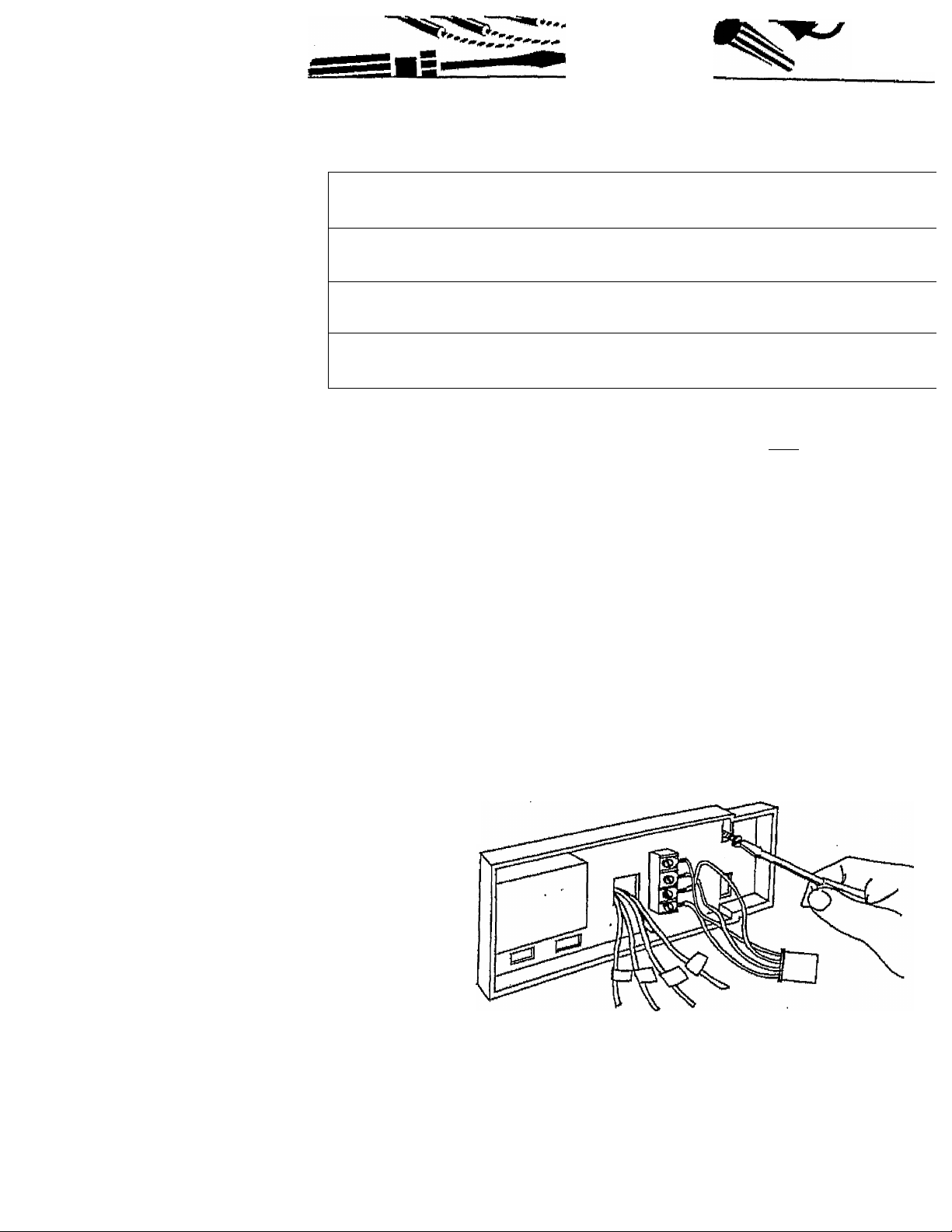
Connect Wires and. Mount Tbermostat Coyer
-4 Match and connect the labeled wires to the
I appropriate coded terminal screws on the
mounting plate (Figure 4). Ignore any wires which may
be present, but which were not connected to your old
thermostat Do not connect these to your Thermostat.
Push excess wire back into hole to prevent
interference with mounting of Thermostat cover.
2
Insert the batteries into your Thermostat as
shown in Figure 5, observing the polarity marked
3
on the unit,
Make sure the HEAT - OFF - COOL switch is In
OFF position and FAN - AUTO switch is in AUTO
4
position. Push all the connectors at the end of each
thermostat wire onto the appropriate spade terminals
HG
V
Ù
on the mounting plate, matching letter codes to wire
colors (See Figures 3 and 4). Connect battery lead
connectors (Figure 5),
Line up the thermostat cover with wallpiate,
snap the thermostat to the wall plate,
5
Switch on the main power. Press the reset
button to reset and start the clock. Use a thin
6
probe such as a straightened paper clip to push
gently the reset button through the hole in the front
panel (Figure 6). The-LCD display should read 12:00
MO and show the current room temperature of your
house. If it shows random numbers, or partial
digits, press the reset button once again,
if you haven't already done so, remove the mylar
label from the display window^
7
HE
Spade Terminal
"'I fST'. I
Figure 4
Battery
Figure 6
Page 8

Programming
IMPORTANT: READ BEFORE YOU BEGIN TO PROGRAM
Remove mylar label covering display window.
1
The PM indicator will appear between 12:00
noon and 11:59 p,m. There is no AM indicator,
2
When the heating or cooling system is actually
operating, "HEAT" or "COOL" will appear on the
3
display.
When you first install the three AA batteries.t the thermostat automatically sets the day.,and ilma to. Monday, 1.2:00
a.m„ shows the current room temperature and is programmed for 68“ in heat mode and 78° in cool mode.
The first data you should enter is the current time and day of week. As the keys are pressed, the display will show
the data being entered.
If power is interrupted the batteries will keep all
programs.
4
If "LOW ВАТТ" appears on the display replace
the batteries.
14-15
i:
EXAMPLE:
If the unit
is being
installed at
9:15 pm,
Saturday,
to set the
thermostat,
you would
press the
keys in the
shown
sequence.
RETURN
MO
!г--оо IS
^\S--0Q
MO
3-00
PM
MO
PM
те
PM
те 7г
PM
P Initial read-out after pressing reset button.
■ Current room temperature is 72“.
■ No indication of program number.
: Press once. Temperature digits disappear, show
time set mode.
■ Press and hold until 9:00 p.m. appears on display.
Press and hold until 15 minutes appears on display.
Ш Press 6 times until Saturday appears on display.
M Returns to normal time and temperature.
■ If return is not pressed it will return automatically in
16 seconds.
Page 9

N»
Programming
TypicaTSuggested Summer and Winter Programs
Studies conducted by the Department of Energy
estimate that setting your thermostat back 10'^F for
two 8-hour periods during winter can reduce your fuel
bid by as much as 30%. By setting your thermostat
up 5° for two 8-hour periods during summer you can
reduce your fuel bill up to 25%,
Your thermostat is capable of holding up to 4
separate programs for heat or cool for each weekd.ay
and 2 programs for each weekend day. You can
program all weekdays, Monday to Friday, to the same
4 programs as shown in the table, or each weekday
can have a different setof 4 programs. Similarly
weekend programs, Saturday and Sunday, can be the
same 2 programs or each weekend day can have a
different set of 2 programs.
Weekday Program (Mon. - Fri.)
Weekday - ^ ^ ^
Program 1 6p00aM
Weekday^ o-on
Program OlOUAM
Weekday- _
Program O OpUUpM
Weekday, . .
Program 4 IlOOpM
Summer
78°P
Summer
84°f
Summer
78°f
Summer
80°f
16-17
Winter
68°f
Winter
60°F
Winter
68°f
Winter
58°f
...V
NOTE: The thermostat program will NOT take
effect immediately after programming of your
Thermostat Monitor but at the next programmed
time/temperature change. The Thermostat is pre
set to 68®F for heat and 78°F for air conditioning,,
So if you want a temperature other than 6S°F or
78®F right away, use the temporary manual
override feature (described on page 29) to enter
your desired temperature setting.
Whan your program becomes effective at the next ,
time/temperature setting, the appropriate corre
sponding program number will appear on the display.
Weekend Program (Sat. -
Weekend . _ _ _
Program! /IUUaM
Weekend- . .
Program ¿ n:UUPM
Summer
78°p
Summer
80°f
Sun.)
Winter
68°f
Winter
58°f
Page 10

Programming
Personal Program Schedule
18-19
Before programming or changing the program^ use
this Personal Program Schedule to determine which
times and temperature settings will best satisfy both
POR WINTER
PROGRAM 4
TIME,
TIME' '
ríMP-
iwe.
liijp-
IWC.
ilMI*
•«e
■ TEMA . •
MONDAY
mm
'/VEDNÉSOAY
THURSDAY
mM
SATURDAY
SUNDAY
PROGRAM 1
nw;
TEMP
TIME
ÍEMP
riME.
lEMPTIME.
ItMP-
EWE.
TEMP ■ '
IWE,
TEMP-
TIME:
Ta,IP:
PROGRAMS
ri№
rfUP
riMt
rrMP
TIME.
TEMP
IIME,
TEMP-
IIME.
TEW*
IIME
TEMPHUE
TEW*'
programs
TIME:
TEMP
TIME
lEMP-
IIME.
lEMP-
TWE.
im
TIME;
TEWP^
Pmaramming Your Thermostat
your comfort and energy saving requirements,
Use a pencil so you can revise your records each
time you change your temperature settings.
FOR SUMMER
PROGRAM t programs PROGRAMS
MONDAY
TUESDAY
WSWESDAY
THURSDAY ■
FRIDAY
SATURDAY
SUNDAY
rwE.
'EMP
TIME
'EW
TIME
W
TME,
TEMPTIME
.W
_________
TIME.
TEMP
1ÌUE.
TEMP
Time
TEMP
TIME,
7E.UP
TIME’
TEMP
TIME
TEMP
TIME.
.
TEMP
r,HE.
TEMP
TIME:
TE.MP
'ME.
"sMP
'■ME,
“MP-
r-WE.
Tpl-IP;
TWE:
TE.MP
TIME:
jm
_______
PROGRAM 4
TIME.
TEMP-
TIME
TEMP;
'niilE:
TEMP;
TIME;
TEMP;
TIME:
liMP;
Familiarize yourself with programming. In this
exampie your thenmostat will be programmed for
winter as per suggested program on pages 16 and
17. However, you can program or change program of
each individual day.
Weekday
Programs
•
Q-/C
PW IL
mfumvim
I
r ^
PROG
MO ru № VIÍ
n-nn CO
u-uu oo
SA
NOTE: 1) The program time is set in increments of
15 minutes.
2) The program temperature is set in increments
of rF.
3) When setting PM time, make sure the "PM"
indicator appears on the display,
■ Normal display of time, temperature, and day of
week.
■ Selects days MO to FR for same set of 4 programs
each day.
m Program indicator (1) is displayed.
m es^F is displayed.
1
■ 0:00 space for time is displayed.
■ MO to FR Is displayed.
Page 11

Programming
Programming Your Thermostat (Cont)
20-21
r ' "1
PR OG
^. ............
HB :
MO W we TH FR
MO ru WB TH FR
j
wo ru we TH FR
MO w m m
MO TUWBTHFR
o^on CP
oou ou
c-n n CO
U-U U UU
n.nn CO
U-U U UO !
O’-Pp CO
D'U U UU
O-DP CO
UU
2
H Press and hold until 6:00 is displayed.
■ Weekday Program 1 is complete.
1
H Program Indicator (2) is displayed.
H Space for time of second program is displayed,
2
N Press and hold until 8:00 is displayed.
2
Clock-advances In inorements-of 16 minutes.
- p Pressing the DOWN arrow each time decreases
one degree.
P When you reach. 60®F, Program 2 is complete.
f '
^
r
PR OG
PR OG
AJO ru WE TH FR
n.nn CO
u^uu ou
r MO ru WE TH FR
■■■■ J»nn CO
PM D^UU uO
MO TU WE TH FR
n.nn CO
U^UU UU
MO TU WE TH FR
tUPp CO
PM / /"UU UU
P Program Indicator (3) is displayed.
P Press and hold until 3:00 p.m. is displayed.
P Weekday Program 3 is ■complete.
P Program Indicator (4) Is displayed.
P Press and hold until 11:00 p.m. is displayed.
A
one degree.
When you reach 58'^F, Program 4 Is complete.
Page 12

Programming
Programming Your Thermostat
22-23
RETURN
Weekend
Programs
°'¡s V
PM J
LJ-00 bS
SA
SA SÜ
M Press RETURN to display current time,
temperature, and day of week. If It is not pressed,
Thermostat will return to current time and
temperature in 15 seconds.
Selects days MQ to FR for same set of 4 programs
each day,
■ Selects weekend days SA, SU for same set of 2
programs each weekend day.
■ SA and SU displayed,
Ü Program indicator (1) is displayed.
SA SU
n.nn CÍ
vuu
SA sy
Press and hold until 7:00 a.m. is displayed.
Weekend Program 1 is now complete.
■ Program'indicator (2) is displayed.
n-nn C(
u-uu c
Press and hold until 11:00 p.m, is displayed.
ll-nn CQ
-iiJ
ft
''I
SA
RETURN
Q-/C
PM D^lD lU
Pressing the DOWN arrow each time decreases
one degree.
When you reach 58®F, Weekend Program 2 is
complete.
II Press to return to display current time, temperature,
and day of week* If it is not pressed, thermostat wlli
automatically return to current time and
temperature in 15 seconds.
Page 13

Programming
Pp^rammi^_________________________________________________________________________________
To program for each individual day separately by a different set of programs, first select day by displaying the day
-i. — -1+-inrtoc> >sm H tomnRraturBS.
24-25
Use
Similarly
psi
IBHV VHBV
' MOW we niFR
$A SU
" MO "
TV
m MO to FR are selected. MO to FR will have
same programs.
V SA and SU will have same program.
■ MO Is selected, program for MO only.
.
to enter programs for Monday,
■ TU is selected.
mmm
Display the day to be programmed and use
enter programs.
NOTE: Another approach to programming is to first program ail weekdays MO through FR and SA and SU as
same programs. Then, display and change the programs of only those days which will have different programs.
Now slide "Heat/Off/Cool" switch to “Heat"
NOTE: If program time remains 0:00, that particular program will not be effective; e.g., if Program #2 has
time 0:00, the thermostat will jump from Program #1 ,to Program #3.
ws
■ WE is selected.
to
Page 14

Programming
Displaying Programs
You may want to review the programs to see that the
settings are compatible with your lifestyle.
Weekday
Program
-27
Page 15

Programming
28-2Í5
NOTE; Tho temperatures you have entered will
NOT take effect immediately, but at the next
program time change. The Thermostat is pre-set
to 68®F in heat mode and 7B^F in cool mode.
If you want a temperature other than 68°F or 78°F
nght away, you must use the manual override
feature described below to enter the temperature
you want.
To Review The Current Temperature Setting:
Press
for 2
seconds
or less:
When your entered program becomes effective,
the corresponding program number will appear on
the display.
After programming, confirm
the new programs by pressing
Current time and temperature.
m 70 indicates the current setting of the therroQstat is
70"F. 68 shows the present room temperature as
6S®R
m If held for more than 2 seconds, you will manually
override your present temperature to a new setting
as explained below.
Manual Override of Program
If You Want to Change the Temperature Without Affecting Your Program:
Press and hold raise temperature. Press and hold to lower temperature.
Temporary Manual Override
In the following example, the present room temperature is 60‘’F and we want to raise the temperature to 70°F
temporarily until the next program.
■ Press arrow to display current set and room
temperatures.
■ Continue pressing arrow. After 2 seconds, the set
teniperature digits will blink and begin to increase
until the button is released at the desired setting (In
this case 7D'’F).
■ Program number disappears.
■ Press return or in 16 seconds it will return to
showing current time and temperature.
■ To display a manual override setting, press either
arrow for less than 2 seconds.
■ When arrow is released, the display will show
current time and temperature,
M Your thermostat is now in manual override mode to
70*^F until the next program indicator number has
disappeared until the next program time comes
into effect.
Page 16

r
Programming
Permanent Manual Override
To Return
To Program*
(’From temporary or permanent manual
override state)
NOTE: You can also return the current program by
pressing «HOLD TEMP” once in, permanent
override mode.
30-31
In the event you wish to hoid your manual override for
vacation or just an extended period of time, follow the
temporary manual override instructions on page 29,
then immediately press HOLD/CLEAR.
This will maintain override setting
Indefinitely, «HOLD" will, appear
on the display.
■ To return immediately to the current
program, press HOLD/CLEAR until
program number appears, "HOLD”
will disappear if you were in
permanent manual override.
Other Features
Temperature Span
Your thermostat is pre-programmed at the factory
to cycle when the temperature rises 1" above
The Energy Monitor
The Energy Monitor measures and stores the amount
of time the heating and air-conditioning system
operates. By pressing the key sequence shown, the
usage can be displayed for the present day, the
or V below the temperature setting; It cannot
be changed.
previous day, and the total. By monitoring on a daily
basis, you can gradually adjust winter or summer
temperature settings and monitor the effect of your
energy conserving efforts.
W Normal display of current time and room
temperature on Saturday.
Page 17

other Features
32-33
Using
The
Energy
Monitor
Ü Press USAGE REVIEW to display amount of time
system has run today (Saturday 12:01 a,m, through
present time).
li Press again to'display total usage in hours and
minutes since usage counter was set to zero, (See
note below.)
m Returns to norma! time and temperature.
m Auto return after 15 seconds if no key Is pressed.
USAGE
/
I 1C DO
USAGE
$A
nj DK
UD U i
UD DO
C^nn UCf
PM
>UU
Ou
NOTÉ: After 999.S9 hours of usage the Energy Monitor will restart from zero.
Resetting Energy Monitor
To reset the usage Energy Monitor back to zero;
simply press and hold the USAGE REVIEW button for
4 seconds.
Page 18

Information
Energy Usage Chart
34-35
The Hunter Set 'n Save II measures, stores and
displays the amount of time your heating or air
conditioning system has operated the present day,
and the previous day.
This Energy Usage Chart will help you discover
your most efficient energy saving comfort zone ,
■DatfiRftdn. . Month. ... ... Dav ,
’
.............................................................
' MON
TUES
by recording your energy usage on a daily or
weekly basis.
Simply enter the daily hours
displayed when you press the
orange Usage Review key.
WED
.... ...........
THURS FRl
.....
Year.
SAT
USAGE
SUN
TOTAL
WEEK1
WEEK 2
WEEKS
WEEK 4
WEEK 5
WEEKS
WEEK 7
WEEK 8
WEEK 9
WEEK 10
WEEK 11
WEEK 12
•
-
Page 19

Troubleshooting |^|
Problem
SCRAMBLED OR DOUBLE DISPLAY (numbers over
numbers
NO DISPUY
entire DISPUY DIMS
PROGRAM DOES NOT CHANGE AT YOUR
DESIRED SETTING
HEAT/FAN DOES NOT COME ON
Solution
1. Remove clear mylar sticker.
1, Check battery connections and batteries.
2, Press reset button once with a small pin and hold (n
for two seconds.
1, Replace batteries.
1. Check that time is set properly to "AM" or "PM,"
2. Check that thermostat is not in "HOLD" mode,
3. Check for correct day setting.
1, Move HG/HE system selector to opposite position.
HEATINQ OR COOUNG DOES NOT GO ON OR OFF
IF TEMPERATURE RISES WHEN AC IS ON/
IF THERMOSTAT CONSISTENTLY READS ROOM
TEMPERATURE TOO HIGH
ERRATIC DISPLAY
IF UNIT CONTINUES TO OPERATE IN OFF POSITION
THERMOSTAT READS EE, HI, LO
If you experience any other problems, call 901-745-9222 from SAM to 5PM. Central Standard time.
1, Check that function switch is in correct position
("HEAT" or "COOL"),
2, There may be as much as 20 seconds delay in the
thermostat turning the system on - wait and check.
3, Check your circuit breakers and switches to ensure
there is power to the system.
4, Replace batteries, .
5, Make sure your furnace blower door is closed properly.
1. Thermistor out of place. The thermister is the small
red part that should fit in the slot at the bottom of
the unit and be exposed to the air.
1. Press the reset button once with a small pin and
hold in for two seconds. Then reprogram.
1. Replace unit.
1. Replace unit
Page 20

Wiring Diagrams
Typical Thermostat
Energy Monitor Thermostat
Micro Computer
1
3 AA Batteries
—Jl
------
Typical 4-wira system.
é-
>
.......
_________
c=
*4=
ro
o
X
Heat
Off „ ,
0
Auto
sa
Fan
m
rqOn
 Loading...