

Page 1
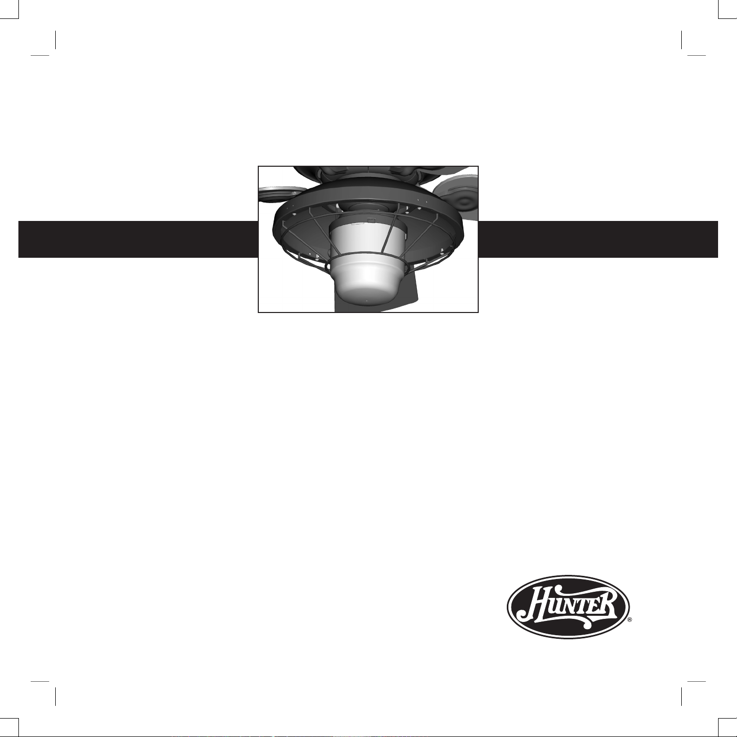
Hunter Outdoor Light Fixture
Installation Instructions
41770-01 05/16/2005
41770-01.indd 5/17/2005, 5:26 PM1
Page 2
CAUTIONS
• Read entire installation instructions carefully before beginning installation and save these instructions.
• To reduce the risk of electrical shock, install this light xture only on
HunterTM fan type 5. Marked suitable for use in wet locations when
installed in a GFCI protected branch circuit. Note: e fan type can
be found on the ceiling fan package or on the name plate label located
on top of the motor housing of the ceiling fan.
WARNINGS
• To avoid possible electrical shock, before installing light xtures disconnect power by turning o the circuit breakers both to the outlet
box and to its associated wall switch location. If you cannot lock the
circuit breakers in the o position, securely fasten a prominent warning device, such as a tag, to the service panel.
• Connect house wiring to the fan before attaching the light xture to
the fan.
• All wiring must be in accordance with national and local electrical
codes. If you are unfamiliar with wiring, you should use a qualied
electrician. Professional installation is recommended.
Troubleshooting
Light does not come on.
1. Pull light pull chain one or two times to see if light comes on.
2. Make sure bulbs are installed properly and lament is not blown.
3. Make sure breakers or fuses are on.
4. Verify that the light power lead is connected at the ceiling. Refer to your
ceiling fan manual for locating assembly and wiring.
Glass rattles.
1. Make sure the glass globe is secure.
For other problems or ques-
tions, contact the Hunter Fan
Company Technical Support
at
1-888-830-1326 or
techsupport@hunterfan.com.
http://www.hunterfan.com
is light xture is for use
only on Hunter Outdoor
ElementsTM Ceiling Fans,
models 28532, 28533, 28534,
28535, and 28536.
41770-01.indd 5/17/2005, 5:26 PM2
Page 3

95420-4.eps
Step 2
Steps 3-4Steps 6-7
1. Disconnect power to the ceiling fan by turning o the circuit breakers
both to the outlet box and to its associated wall switch location.
2. Align the three holes in the gasket with the three holes in the switch housing mounting plate. Partially install two screws.
3. Place the keyhole slots in the upper rain shield over the two partially
installed screws and turn the upper rain shield counter clockwise.
4. Place the keyhole slots in the upper switch housing over the two partially
installed screws and turn the upper switch housing counter clockwise.
5. Install a screw into the third hole. Securely tighten all three screws.
6. Feed the two wires from the tter through the center hole in the lower
switch housing.
7. Attach the tter to the lower switch housing with the two screws. Securely tighten the two screws. WARNING: Improper installation could cause
the light xture to fall.
8. Remove the wire nut from the black/white wire in the lower switch housing. Use this wire nut to connect the black/white wire from the lower
switch housing to the black wire from the light xture. Remove the wire
nut from the white wire in the lower switch housing. Use this wire nut to
connect the white wire from the lower switch housing to the white wire
from the light xture.
95420-5.eps
Step 5
Gasket
Upper
Rain
Shield
Upper Switch
Housing
Lower Switch
Housing
Fitter
41770-01.indd 5/17/2005, 5:26 PM3
Page 4

9. Connect the 9-pin plug connectors. Attach the lower switch housing to
the upper switch housing with the three thumb screws.
10. Attach the lower rain shield to the upper rain shield with four screws.
Securely tighten all four screws.
11. Attach the wire cage to the lower rain shield with four screws. Securely
tighen all four screws.
12. Install a 75 W Max A-19 bulb.
13. Raise the glass globe and align the indents in the glass globe with the tabs
on the tter. Twist the glass globe clockwise to secure.
14. Restore power to the ceiling fan.
95420.eps
Step 9
Steps 10
Steps 12-13
Step 11
Lower Rain
Shield
Wire Cage
Glass
Globe
41770-01.indd 5/17/2005, 5:26 PM4
Page 5

41770-01.indd 5/17/2005, 5:26 PM5
Page 6

Hunter Fan Company
2500 Frisco Avenue
Memphis, Tennessee 38114
Printed in China & Taiwan
is Light Fixture weighs 7.0 lbs.
© 2005 Hunter Fan Company
41770-01.indd 5/17/2005, 5:26 PM6
 Loading...