

Page 1
For Your Records and Warranty
Assistance
Model Name: _____________________
Catalog/Model No.: ________________
English Español
Date Purchased: ___________________
Where Purchased: _________________
For reference also attach your receipt or a
copy of your receipt to the manual.
Hunter Fan Company 41532-01 • 10/22/13
Page 2
Welcome
READ AND SAVE THESE INSTRUCTIONS
Your new Hunter® ceiling fan is an addition to your home or office that will provide comfort and
performance for many years. is installation and operation manual gives you complete instructions for
installing and operating your fan.
We are proud of our work. We appreciate the opportunity to supply you with the best ceiling fan available
anywhere in the world.
Before installing your fan, for your records and warranty assistance, record the information from the
carton and the Hunter nameplate label (located on the top of the fan motor housing).
Cautions and Warnings
• Read this entire manual carefully before beginning installation. Save these instructions.
• Use only Hunter replacement parts.
• To reduce the risk of personal injury, attach the fan directly to the support structure of the building
according to these instructions, and use only the hardware supplied.
• To avoid possible electrical shock, before installing your fan, disconnect the power by turning o the
circuit breakers to the outlet box and associated wall switch location. If you cannot lock the circuit
breakers in the o position, securely fasten a prominent warning device, such as a tag, to the service
panel.
• All wiring must be in accordance with national and local electrical codes and ANSI/NFPA 70. If you are
unfamiliar with wiring, use a qualified electrician.
• To reduce the risk of personal injury, do not bend the blade attachment system when installing,
balancing, or cleaning the fan. Never insert foreign objects between rotating fan blades.
• To reduce the risk of re, electrical shock, or motor damage, do not use a solid-state speed control with
this fan. Use only Hunter speed controls.
• is product conforms to UL STD 507 and is certied to STD C22.2 No.113.
• Wash your hands after your fan installation is complete.
• Use only with light kits marked suitable for damp locations.
Table Of Contents
Getting Ready .........................4
Pre-Installation ........................5
Installing Ceiling Hardware ............6
Hanging e Fan ......................7
Wiring the Fan ........................9
Installing e Canopy..................10
Lubrication............................11
Fan Blade Assembly ...................12
Operation And Care...................13
Energy Star ............................14
Troubleshooting Guide . . . . . . . . . . . . . . . . 15
Page 3
Optional Accessories
Understanding Mounting
Hunter’s patented mounting system provides you maximum ease in installing your fan. is fan was
designed to be mounted only on flat ceilings and can be used only on ceilings no less than 8 feet high.
Considering Optional Accessories
Consider using Hunter’s optional accessories, including a wall-mounted or remote speed control.
To install and use the accessories, follow the instructions included with each product. For quiet and
optimum performance of your Hunter fan, use only Hunter speed controls.
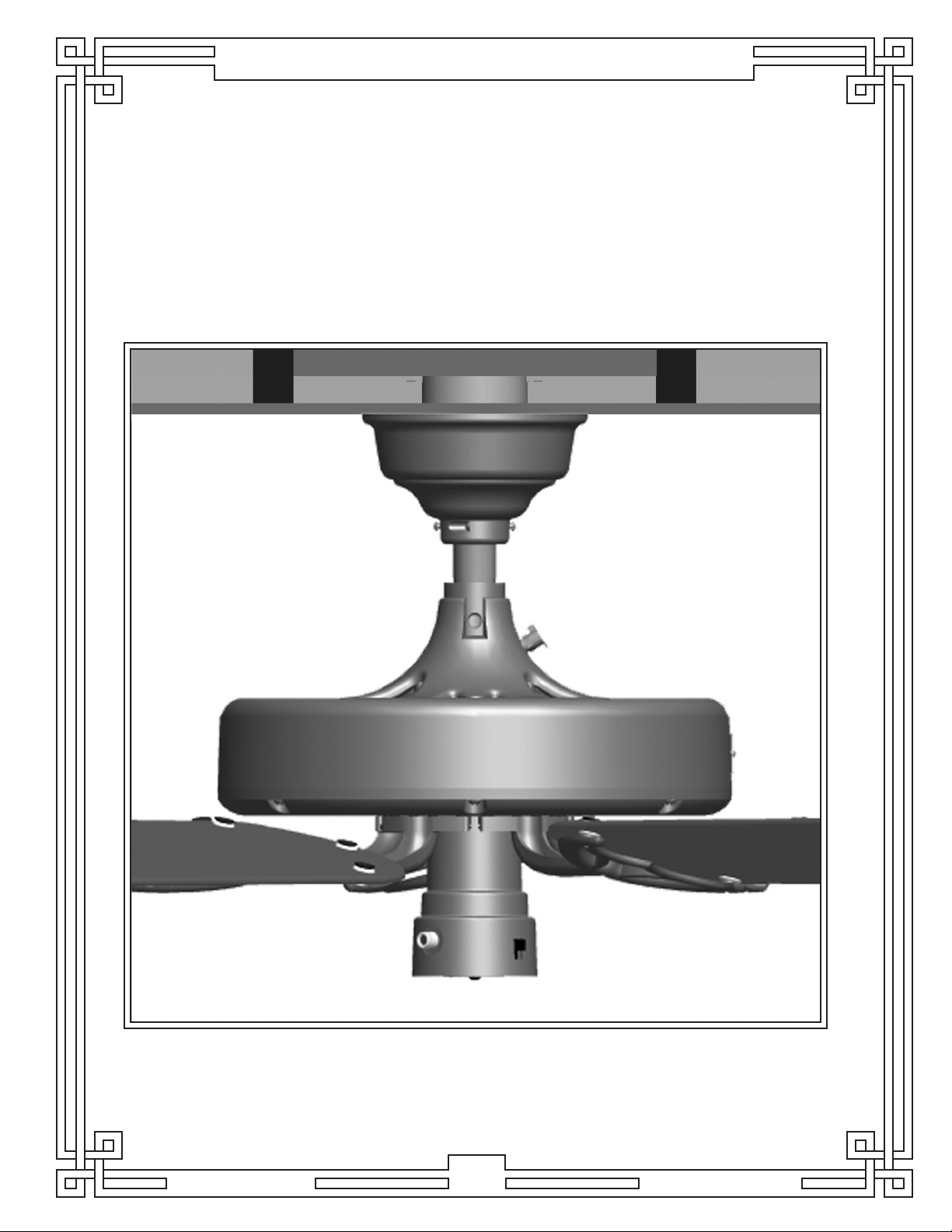
Standard Mounting
hangs from the ceiling by a
downrod (included), recommended
for ceilings 8 feet or higher
Hunter Fan Company 41532-01 • 10/22/13
3
Page 4
Getting Ready
To install a ceiling fan, be sure you can do the following:
• Locate the ceiling joist or other suitable support in ceiling.
• Drill holes for and install wood screws.
• Identify and connect electrical wires.
• Lift 70 lbs (31.8 kg) pounds.
If you need help installing the fan, your Hunter fan dealer can direct you to a licensed installer or
electrician.
Gathering the Tools
You will need the following tools for installing the fan:
• Adjustable wrench or pliers
• Electric drill with 11/64” bit
• Standard screwdriver (magnetic tip recommended)
• Phillips-head screwdriver (magnetic tip recommended)
• Ladder (height dependent upon installation site)
• 3/8” socket wrench
Checking Your Fan Parts
Carefully unpack your fan to avoid damage to the fan parts. Refer to the included Parts Guide. Check
for any shipping damage to the motor or fan blades. If any parts are missing or damaged, contact your
Hunter dealer or call Hunter Technical Support Department at 1-888-830-1326.
Installing Multiple Fans?
If you are installing more
than one fan, keep the blade
assemblies in sets as they were
shipped.
Hunter Fan Company 41532-01 • 10/22/13
4
Page 5
Pre-Installation
Pre-Installation
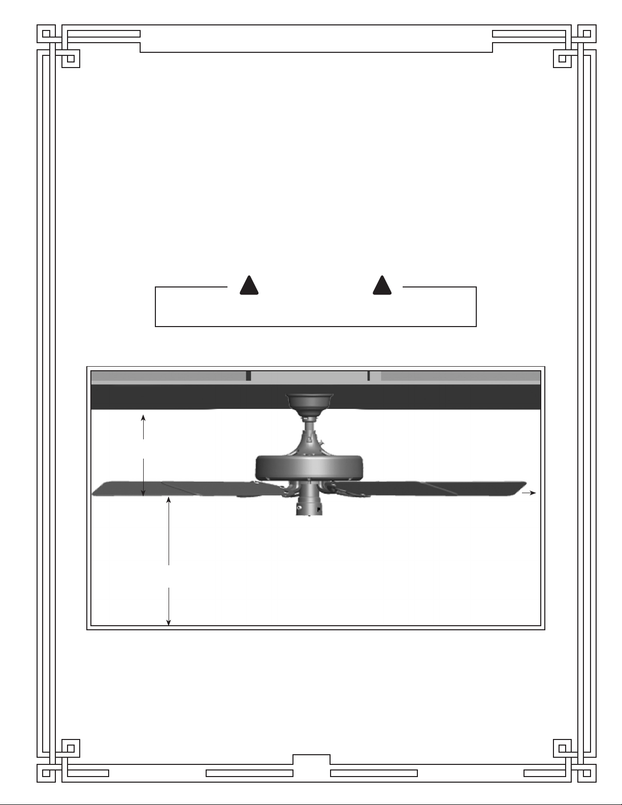
Select installation site: Normally this is near the center of the room, often replacing a light xture.
Make certain that ample clearance is left for the rotating fan blades. For maximum efficiency, no
obstruction (walls, posts, etc.) should be within 30” of the tips of the blades (see Fig. 1).
Your Hunter fan comes with the proper hardware to hang the fan from a 8 foot ceiling so the fan
blades will be 12” from the ceiling and approximately 7 feet from the oor (see Fig. 1).
NOTE: On vaulted ceilings, up to 45° pitch, you may want to use the Hunter Vaulted Ceiling
Mounting Kit. is kit can be purchased via our website or our parts and service number.
! !
CAUTION
NEVER LIFT THE MOTOR BY THE WIRES.
LET MOTOR REST IN THE CARTON LINER FOR PROTECTION.
12” (ref.) Minimum
7’ From Floor
Fig. 1
30” Clearance
Hunter Fan Company 41532-01 • 10/22/13
5
Page 6

Installing Ceiling Hardware
! !
CAUTION
DO NOT USE LUBRICANT ON SCREWS
1. Drill two (2) 1/4” diameter holes 2-9/16” apart through the back of the outlet box into the cross
brace 2" deep. ese holes are for the U-bracket bolts. Install rubber bushing and pin into the
u-bracket. Use a 3/8” wrench to install the (2) 3 1/2” lag bolts to secure the U-bracket to the joist
(see Fig. 2).
Exploded View Installed View
Cross
Brace
Rubber
Bushing
and Pin
Lag Bolt
Fig. 2
U-Bracket
Ceiling
Outlet
Box
3 1/2” Lag Bolt
Standard
Mounting
Style
Support
Structure
Ceiling
Outlet Box
(required)
Use Standard Mounting or Low-Profile Mounting to
hang the fan from a flat ceiling.
Hunter Fan Company 41532-01 • 10/22/13
6
Page 7

Hanging The Fan
! !
CAUTION
BE SURE TO TIGHTEN THE HANGER PIPE INTO THE FAN, AND THE
HANGER BRACKET ONTO THE PIPE. TIGHTEN THE 2 SET SCREWS, AS
DESCRIBED IN STEP 7, TO PREVENT THE FAN FROM FALLING. YOUR FAN
MAY WEIGH UP TO 50 LBS. ALL OF THE FOLLOWING STEPS MUST BE
FOLLOWED IN ORDER TO ENSURE A SECURE MOUNTING.
1. Feed the wires from the top of the fan motor through the hanger pipe (see Fig. 3).
2. Back out the motor housing set screw (Do not completely remove from fan) in neck of fan motor
housing and hanger bracket assembly so the hanger pipe can be screwed in.
3. Screw the pipe into the fan until tight (at least 4 1/2 turns) (see Fig. 4).
NOTE: Some of the pipe threads may still be visible.
Motor
Housing
Fig. 3
Wires
Hanger
Pipe
Motor Housing
Set Screw
Fig. 4
Hunter Fan Company 41532-01 • 10/22/13
7
Page 8

Hanging The Fan
4. Back out the set screw on the hanger bracket.
5. Feed the 3 wires through the hanger bracket assembly and screw the hanger bracket onto the
hanger pipe until tight (at least 3 turns) (see Fig, 5).
6. Use pliers to tighten both the hanger bracket assembly and the hanger pipe together.
7. Tighten the set screw in the motor housing and the hanger bracket assembly (see Fig 6).
Hanger
Bracket
Hanger
Pipe
Hanger
Bracket
Set Screw
Motor Housing
Set Screw
Fig. 5 Fig. 6
8. Be sure that the pin is centered in the rubber bushing.
9. Lift the fan by the motor housing. Hook the hanger bracket assembly onto the rubber bushing
pin. Ensure both ends of the pin are outside the hanger bracket assembly (see Fig 7).
and
Rubber
Bushing
and Pin
Hanger
Bracket
Assembly
Fig. 7
Hunter Fan Company 41532-01 • 10/22/13
8
Page 9

Wiring the Fan
! !
CAUTION
BE CERTAIN THAT THE ELECTRICITY IS TURNED OFF AT THE
MAIN PANEL BEFORE STARTING THIS SECTION.
NOTE: All wiring must be in accordance with
national and local electrical codes and ANSI/
NFPA 70-1999. If you are unfamiliar with
wiring, use a qualified electrician.
Wall switches are not included. Select an
acceptable general-use switch in accordance with
national and local electrical codes.
1. Before attempting installation, make sure the
power is still o.
2. To connect the wires, hold the bare metal
leads together and place a wire connector over
them, then twist clockwise until tight. For all
these connections use the wire connectors
provided.
3. Connect the bare or green ground wire
(grounding) from the ceiling to the side of the
hanger bracket assembly.
4. Connect the white wire (grounded) from the
ceiling to the white wire (grounded) from the
fan.
5. Connect the remaining wires as follows:
Dual Switch Wiring (see Fig. 8):
• e black wire (ungrounded) from the ceiling
to the black wire (ungrounded) from the fan.
• e blue wire (ungrounded) from the fan to
the wire (ungrounded) from the wall switch.
Single Switch Wiring (see Fig. 9):
• The black wire (ungrounded) from the ceiling
to the black (ungrounded) and the blue wire
(ungrounded) from the fan.
Wire Connector
Fig. 8
! !
CAUTION
NO BARE WIRES OR WIRE STRANDS SHOULD
BE VISIBLE AFTER MAKING CONNECTIONS.
6. Turn the splices upward and push them
carefully into the outlet box.
7. Spread the wires apart, with the grounded
wires on one side of the outlet box and the
ungrounded wires on the other side of the
outlet box.
Hunter Fan Company 41532-01 • 10/22/13
Fig. 9
9
Page 10

Installing The Canopy
NOTE: Your canopy comes pre-assembled. Uninstall the canopy screws and separate the two halves
of the canopy before continuing to step 1.
1. Assemble canopy halves around pipe, and loosely install the canopy assembly screws.
2. Slide canopy up close to ceiling.
3. Tighten the canopy assembly screws (see Fig. 10).
4. Tighten the canopy set screw (see Fig. 10).
Canopy
Canopy Set Screw
Canopy Assembly
Screw
Fig. 10
Hunter Fan Company 41532-01 • 10/22/13
10
Page 11

Lubrication
! !
CAUTION
DO NOT TURN FAN ON UNTIL LUBRICATION HAS BEEN ADDED. TO OPERATE THE FAN
WITHOUT OIL OR WITH LOW OIL WILL VOID YOUR WARRANTY.
Adding Oil
1. Your fan has been shipped without oil in the motor.
2. A 1-ounce tube of high grade SAE 10 non-detergent oil is packaged in the sack parts.
3. All of the oil in the tube must be put into the fan.
4. Cut the tip o the end of the tube and place the tube into the oil hole (see. Fig. 11).
NOTE: To avoid overowing during lling, allow oil to gravity ow about one minute to ll the oil
reservoir. It may be necessary to puncture the tube to allow air in.
Checking Oil
1. Check oil level immediately after filling the reservoir and every 1 to 5 years thereafter.
2. To check oil, bend an ordinary pipe cleaner into 1/2” long hook and dip it into the oil reservoir.
3. If the oil touches the end of the pipe cleaner, the fan has ample oil. If it does not touch, add SAE 10
non-detergent oil slowly until it touches the pipe cleaner (see. Fig. 12).
Oil Tube
Oil Hole
Pipe
Cleaner
Oil
Reservoir
Fig. 11
Fig. 12
Your Original Hunter’s Unique Lubricating System
e bearings are submerged in a bath of oil. e oil moves up a spiral groove in the shaft, lubricating
all bearing surfaces as the fan operates. is unique lubrication system is one reason your Original
Hunter Ceiling Fan will last a lifetime. Typically this Lubrication System does not normally “use up” or
require the addition of extra oil once the oil reservoir has been filled to the correct level. We
recommend that you check the oil reservoir once per year to ensure proper lubrication. Failure to
maintain proper oil level in the fan could result in operational issues or failures.
Hunter Fan Company 41532-01 • 10/22/13
11
Page 12

Fan Blade Assembly
! !
CAUTION
TO REDUCE THE RISK OF PERSONAL INJURY, DO NOT BEND THE BLADE
BRACKETS WHEN INSTALLING THE BRACKETS, BALANCING THE
BLADES, OR CLEANING THE FAN. DO NOT INSERT FOREIGN OBJECTS
IN BETWEEN ROTATING FAN BLADES.
Fan Blade Assembly
1. Your fan may include blade grommets. If the fan has grommets, insert them by hand into the holes
on the blades (see Fig. 13).
2. Attach each blade to a blade iron using three blade assembly screws. If you used grommets, the
blades may appear slightly loose after the screws are tightened. is is normal (see Fig. 14).
3. For each blade, insert one blade mounting screw through the blade iron, and attach lightly to the
fan. Insert the second blade mounting screw, then securely tighten both mounting screws.
NOTE: With some fans you have an option to install four or five blades. For five blades, mount to the
outer row of holes on the motor. For four blades, use the inner row (see Fig. 14).
Fig. 13
Blade
Grommet
Grommet
Outer Row
Inner Row
Blade
Assembly
Screws
Blade
Mounting
Screw
Hunter Fan Company 41532-01 • 10/22/13
12
Fig. 14
Page 13

Operation And Care
1. e fan pull chain controls power to the fan. e pull chain has four settings in sequence: High,
Medium, Low, and O.
• Pull the chain slowly to change settings.
• Release slowly to prevent the chain from recoiling into the blades.
2. For cleaning nishes, use a soft brush or lint-free cloth to prevent scratching. A vacuum cleaner
brush nozzle can remove heavier dust. Remove surface smudges or accumulated dirt and dust
using a mild detergent and a slightly dampened cloth. You may use an artistic agent, but never
abrasive cleaning agents as they will damage the finish.
3. Clean wood finish blades with a furniture polishing cloth. Occasionally, apply a light coat of
furniture polish for added protection and beauty.
To Reverse The Flow Of Air.
1. Move the directional lever down for down draft (see Fig. 15).
2. Move the directional lever up for up draft (see Fig. 15).
Fig. 15
UP
Directional
Lever
DOWN
Hunter Fan Company 41532-01 • 10/22/13
13
Page 14

Energy Star
Hunter fans have the power to cut your cooling costs up to
40%.
Beat the High Cost of Cooling
e air movement created by a Hunter ceiling fan lets you
set your thermostat higher and still stay comfortable. Every
degree you raise the thermostat saves up to 7% on energy
costs. So, you can cut back on expensive air conditioning...
and save up to 40%* on cooling. In winter, your Hunter fan
recirculates warm air and saves up to 10%* on heating bills.
*On average at low speed settings. Your savings may vary
based on climate, building type and thermostat setting.
Save Energy and Money While Protecting the Environment
Congratulations! You’re saving energy and money while
protecting the environment by purchasing this ENERGY
STAR qualied Hunter ceiling fan! With this purchase, you are
doing your part to protect the environment. In 2010, ENERGY
STAR qualied ceiling fans are projected to cut air pollution
by more than 500 million pounds!
Your new ceiling fan has earned the ENERGY STAR label
because it meets high energy efficiency specifications set by
the Environmental Protection Agency (EPA). ENERGY STAR
labeled ceiling fans save energy because they have more
efficient fan motors and air delivery due to more aerodynamic
blade congurations. Ceiling fan models bearing the ENERGY
STAR label move air 14-20% more eciently than typical
ceiling fan models. For more information on ENERGY STAR
visit www.energystar.gov.
Hunter Fan Company 41532-01 • 10/22/13
14
Page 15

Troubleshooting Guide
Problem: Nothing happens; fan does not move.
1. Turn power on, replace fuse, or reset breaker.
2. Check all connections according to the wiring the fan section.
3. Pull the pull chain to ensure it is on.
Problem: Noisy operation.
1. Tighten the blade assembly screws until snug.
2. Check to see if the blade is cracked. If so, replace all the blades.
Problem: Excessive wobbling.
1. If your fan wobbles when operating, use the enclosed balancing kit and instructions to balance the
fan.
If you need parts or service assistance, please call
888-830-1326 or visit us at our WEB site at
http://www.hunterfan.com.
Hunter Fan Company
7130 Goodlett Farms Pkwy. #400
Memphis, Tennessee 38016
Hunter Fan Company 41532-01 • 10/22/13
15
 Loading...