

Page 1
yCPr=
?
The Or ígma l
Ov er 80 yea rs of lea der shi p
fe
JROBBINS
niVIYERS
THE PAST
It was 1886 when the Hunter Brothers of
Fulton, New York launched the business.
Other interesting things happened that year
too. Geronimo surrendered. President Grover
Cleveland got married in the White House.
Robert Peary headed for the North Pole.
So Hunter Is Historic
Robbins & Myers, with which Hunter merged
in 1949, is even more so. R & M was founded
in 1878 in Springfield, Ohio. Both companies
were national leaders in the development of
fans, and the merger of their experience and
know-how was good news for customers ail
over the country.
So the name is now Comfort Conditioning
Division,Robbins & Myers, Inc. The address
is 2500 Frisco Avenue, Memphis, Tennessee
38114. The products are still the world's
best fans.
.............................
yet
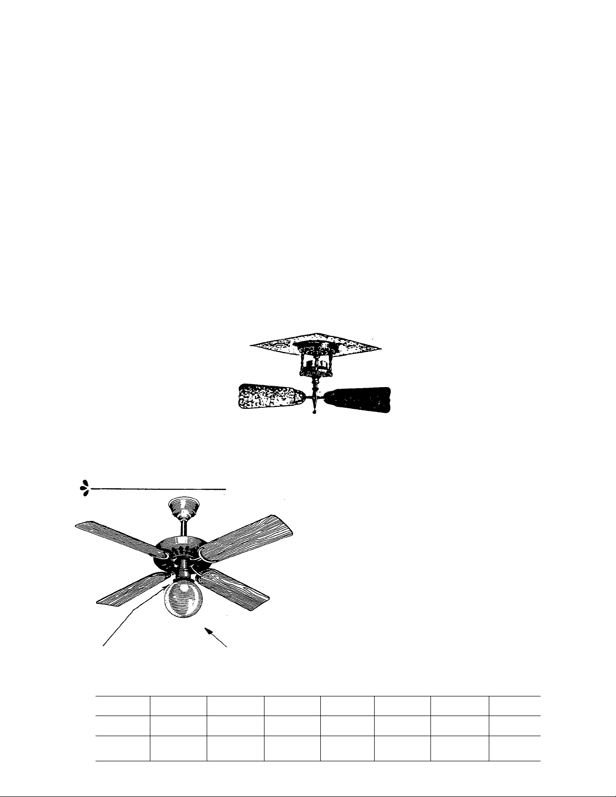
OPTIONAL LIGHT KIT AND GLOBE
AVAILABLE
Tuerk
“Artistic” Ceiling Fans
In Three Gracle.s, Nos. 1.2 and 3
(From our 1903 Catalog)
PRESENT SPECIFICATIONS
THE PRESENT
Operating at slow speeds, HUNTER
Ceiling Fans are ideal for quiet
circulation of large volumes of air at
low velocities. Extremely quiet
operation, dependability and
inexpensive installation have made
HUNTER Ceiling Fans the standard
for hotels, restaurants, offices, stores
and homes since 1886. They are ideal
for meat and fruit counters, as
vestibule-fan in stores, and especially
over open doorways to divert insects.
HUNTER Ceiling Fans are more
sought after today by home owners
and business people than in history
for their look of antiquity and
decorative value as well as their
efficient and quiet air circulating
qualities.
1. Two speed motors
2. 120v., 60HZ., single phase operation.
3. Fan blades can be mounted as close
as 9 1/2" from ceiling on some mod
els. See chart in installation instruc
tions for specific clearances required.
4. Fans available in many colors and
finishes.
5. Optional light kit available. Consult
catalog for specific information.
6. Adaptair blades available for 52"
model. A single control changes
blade pitch from downflow to upflow.
7. Solid state, wall mounted, variable
speed control, (catalog No. 22166),
is available for the 52" model for
fully adjustable speed control.
FAN SIZE
36" 2 4000
52”
SPEEDS
2
CFM (NEMA)
7000
RPM HIGH
275
200
RPM LOW
175
115
WATTS HIGH
85
155
WATTS LOW
55
80
SHIP WT.
21
45
I
Page 2
INSTALLATION INSTRUCTIONS
Note; Your Hunter fan has been carefully manufactured, using the finest of materials and craftmanship for long life and simplicity
of installation and operation. To insure quiet operation and full efficiency of the unit, please follow the included instructions
carefully, observing the “caution” notes at the beginning of each step. The basic instructions cover a standard installation in a drywall
or plaster ceiling. The mounting instructions for additional wood and concrete installations are covered In an additional section following
the basic Instructions below.
STEP 1. PRE-INSTALLATION INSTRUCTIONS
A. Select installation site. Check to make certain that in normal use no object can come in contact with the rotating fan blades.
Mounting site should also meet the pre-cautions listed in step 3 below.
B. Installation hardware is included for a standard drywall or plaster ceiling. You will need a 4" X 1-1/2" octagon junction
box and wire nuts (2) which can be purchased from any hardware store or electrical supply house.
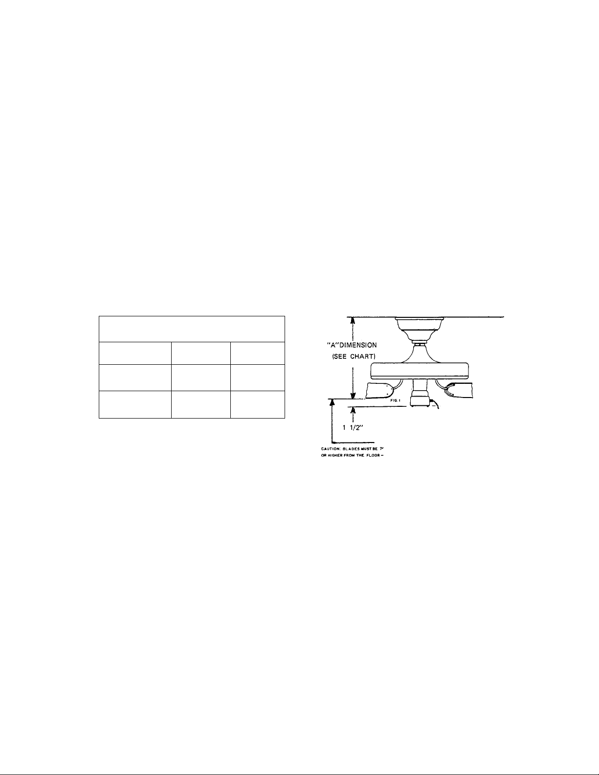
C. The pipe nipple included will mount the unit so that the bottom of the fan blades will be approximately 10" from the
ceiling. If the ceiling height is over eight feet, you may wish to increase the distance to the ceiling by increasing the length of
the mounting pipe. To determine new pipe length, take desired distance from ceiling to fan blade lower edge (Dimension
"A" in Fig. 1), add 2" to it, then subtract minimum hanging dimension as req'd from chart. Discard 2" nipple supplied with
unit if longer pipe section will be used.
CAUTION: IN DETERMINING PIPE LENGTH, BE CERTAIN THAT FAN BLADES WILL REMAIN AT LEAST 7'ABOVE
FLOOR TO AVOID STRIKING TALL PERSONS OR OBJECTS. ALSO, BE CERTAIN THAT PIPE PURCHASED IS .109"
WALL MINIMUM TO PROPERLY SUPPORT FAN. PIPE MUST HAVE 3/4"-14 NPT THREAD EACH END.
MINIMUM HANGING DIMENSIONS
(USING 2X2" PIPE NIPPLE SUPPLIED)
TYPE OF MOUNT
SEMI-RECESS
(SEE FIG. 2)
SURFACE
(SEE FIG. 3)
"A" FOR
36" FANS
10"
10 X2"
"A"FOR
52" FANS
12"
12X2"
STEP 2. INSPECTION OF UNIT
A. Unpack unit carefully to avoid damage to any components.
B. Check for any shipping damage to motor assembly and fan blades. If more than one unit is being installed, keep fan
blades in sets of four, since they are shipped as a matched set. Should one of the fan blades receive damage during shipment,
return all four blades for replacement.
C. Check contents for assembly hardware. Make certain that a bag of parts and a canopy have been included with the unit.
STEP 3. INSTALLATION OF CEILING MOUNTING HARDWARE
CAUTION: YOUR CEILING FAN MAY WEIGH UP TO 50 LBS, SO THE FOLLOWING NORMAL
PRECAUTIONS MUST BE TAKEN TO INSURE THAT THE UNIT WILL NOT FALL FROM THE CEILING.
A. Wood joist must be sound and of sufficient size to support a SOib. ioad, but in no case be smaiier than l->/2" X 3-V2” (nominal 2X4 size).
B. Edge of drilled hole must be no closer than V2” from edge of joist to avoid splitting wood when hook is threaded in.
C. Use only 9/32” drill so hook will have greatest holding power without splitting wood.
D. Do not mount directly to unsupported drywall celling or to unreinforced ceiling wiring box.
A. The unit is designed to fit an octagon junction box surface mounted or semi-recessed into drywall or plaster ceilings as shown
in Fig. 2 and 3. Mount this junction box to the ceiling joist at desired location. Note: Fan is supported independently of
Junction box, so box will not require special mounting.
B. Drill 9/32" hole 3" deep in center of joist. Thread hook into hole to 1" of inside of box as shown in Fig. 2 and Fig. 3. Use
vaseline, soap or oil to lubricate hook threads.
Page 3

STEP 4: ROUGH-IN WIRING
CAUTION: BE CERTAIN THAT ELECTRICITY IS TURNED OFF AT MAIN PANEL BEFORE ANY WIRING IS DONE
A. Bring Electrical cable into octagon box and attach with an approved connector.
Make certain that wiring meets all national and local electrical codes. See Fig. 4.
STEP 5; ASSEMBLY OF FAN AND HANGING FAN ON HOOK
A. Remove card board sleeve from carton and place on working surface. Carefully set motor into sleeve as shown in Fig. 5.
B. Feed wires from top of motor through pipe nipple. See Fig. 5.
C. Thread pipe nipple into fan until tight (at least 4’/2 turns). Thread pipe nipple into hanger bracket
untii tight (at least 3 turns). Tighten setscrew in hanger bracket (alien wrench supplied) and set
screw in motor housing. See Fig. 6.
D. Place rubber bushing on hook. Lift fan and hook hanging bracket onto pin in rubber bushing. See Fig. 6.
STEP 6: FINAL WIRING AND CANOPY INSTALLATION
A. Connect electrical supply leads to leads from, motor, using approved connectors.
Ground wire must be attached to ground screw as shown in Fig. 7.
B. Install split canopy by pressing two halves together around pipe, placing pins
on one half into holes in other half. Screw halves together using two 3/8" long
self-threading screws provided. Allow 1/8" min gap between ceiling and canopy
for fan movement. Use extra screw in center of hub to assist in clamping canopy
to pipe. See Fig. 7.
STEP 7: FAN BLADE INSTALLATION
Blades are shipped in sets matched by weight. A weight mark appears on the back of
each blade. Install blades in sets of matching number, one opposite the other. In some
instances, all blades may have the same weight mark and may be installed in any posi
tion. Replacement blades should be ordered in sets of 2.
Insert a 12-24 Fillister Head Screw (provided) in hole in blade bracket. Use screwdriver
to hold in place. Align blade holes with mtg. holes in hub, by turning screw and re-adjus
ting blade bracket until screw mates with threaded hole.in hub. Repeat for 8 screws.
GAOUMO SCAEW
CEILING
CANOPy HAIP
Page 4

STEP 8: LUBRICATION OF BEARINGS
CAUTION; DO NOT OPERATE FAN WITHOUT LUBRICATION. SUCH OPERATION
COULD RESULT IN PERMANENT DAMAGE TO THE MOTOR.
Fans are shipped without oil. A one-ounce bottle or tube of high grade SAE 20 oil is packed with fan. To
avoid overflow during filling, add oil very slowly, about 1/4 of the bottle/tube every 10 seconds.
To check oil supply; Bend the end of a pipe cleaner into a 1/2" long hook and insert it into the oil reser
voir as shown In FIG. 8. if oil touches the pipe cleaner, the fan has ample oiUf it does not touch, add
SAE 20 oil slowly until it just touches pipe cleaner. Under normal use, oil level should be checked once
per year.
STEP 9: OPERATION OF FAN
A. Turn electrical service on at main panel
B. Attach pull cord to switch chain. Switch operates in sequence. "High" - "Off" • "Low" • "Off", or "High" • "Low" - "Off".
Pull cord SLOWLY to operate. Also, release the cord SLOWLY so as to prevent cord from flying up into blades, possibly resulting
in damage to blades or injury.
NOTE: DO NOT USE AN ABRASIVE CLEANSER ON FAN. A MILD DETERGENT WILL CLEAN MOST UNITS TO THEIR
ORIGINAL APPEARANCE.
INSTALLATION IN CONCRETE CEILING
FOLLOW BASIC INSTALLATION INSTRUCTIONS. INCLUDING CAUTIONS, MAKING THE CHANGES AS LISTED BELOW.
CAUTION:
A) FOR CONCRETE MOUNTING THE DRILLED HOLE MUST BE AS RECOMMENDED BY THE MANUFACTURER OF THE ANCHOR
(THIS IS USUALLY MARKED ON THE ANCHOR) AND MUST BE DRILLED AT LEAST 1/2" DEEPER THAN THE LENGTH OF THE ANCHOR.
B) THE HOLE MUST BE MADE WITH A SUITABLE CARBIDE TIPPED MASONRY DRILL WITH A TIP DIAMETER CONFORMING TO
ANSI B94.12 ( 5/8" NOMINAL = .660/ .650 ACTUAL)
C) THE ANCHOR MUST BE NEW AND UNUSED.
D) THE CONCRETE CEILING MUST BE SOUND AND FREE OF CRACKS OR VOIDS IN THE VICINITY OF THE MOUNTING HOLE.
E) THE ANCHOR MUST BE HAMMERED IN FLUSH WITH THE SURFACE OF THE CONCRETE.
F) THE HOOK MUST NEVER BE BACKED OUT. IF THE HOOK CAN BE TURNED EASILY ( BY HAND ),
DO NOT HANG FAN.
A. Drill hole In concrete ceiling to receive 3/8 x 2Vz lag screw expansion shield
anchor, "STAR STA2IN"#1825 - 00300 or equal (not furnished). Install shield in
hole observing all cautions above, and thread hook Into shield to depth shown in
Fig. 9. Do NOT back hook out to achieve the 1" dimension.
B. When properly installed, such an anchor wiil hold a proof test load of over 900 lbs.
and is rated for a safe working load of over 240 lbs.
C. Proceed with the installation of the fan per the basic installation instructions.
3n*x21Q'LAQ SCREW
ADDITIONAL WOOD INSTALLATIONS
USE THE SPECIFIC FIGURE BELOW SHOWING THE MOUNTING DESIRED AS
A GUIDE IN CONJUNCTION WITH THE BASIC MOUNTING INSTRUCTIONS.
PITCHED BEAM MOUNT
MOUNTING ON SPAN SeTWEEN PITCHED SEAMS
Hunter
COMFORT CONDITIONING DIVISION, Robbins & Myers, Inc.
2500 Frisco Ave., Memphis, Tenn. 38114
FORM NO. 40590 REV. 5-81
CONCRETE CEIUNQ MOUNT
HORIZONTAL BEAM MOUNT
JRpBBINS
HIVfYERS
 Loading...