

Hunter 21587 Owner's Manual
For Your Records and
Warranty Assistance
For reference, also attach your receipt or a copy
of your receipt to the manual.
Type 2 ModelsType 2 ModelsType 2 Models
__________________________________________
Model Name
__________________________________________
Model No.
__________________________________________
Date Purchased
__________________________________________
Where Purchased
Owner’s Guide and Installation Manual
English Español
Form# 42724-01
20100701
©2010 Hunter Fan Co.
Table Of Contents
1 • Getting Ready. . . . . . . . . . . . . . . . . . . . . . 6
2 • Installing the Ceiling Plate . . . . . . . . . . 7
3 • Assembling and Hanging the Fan . . . 8
4 • Wiring the Fan . . . . . . . . . . . . . . . . . . . . . 9
5 • Installing the Canopy and Canopy Trim
Ring . . . . . . . . . . . . . . . . . . . . . . . . . . . . . . 10
6 • Assembling the Blades. . . . . . . . . . . . . . 11
7 • Completing Your Installation With or
Without a Bowl Light Fixture . . . . . . 12
8 • Operating and Cleaning Your Ceiling
Fan . . . . . . . . . . . . . . . . . . . . . . . . . . . . . . . 16
9 • Troubleshooting. . . . . . . . . . . . . . . . . . . . 17
Welcome
Your new Hunter® ceiling fan is an addition to your home or oce that
will provide comfort and performance for many years. is installation
and operation manual gives you complete instructions for installing
and operating your fan.
We are proud of our work. We appreciate the opportunity to supply
you with the best ceiling fan available anywhere in the world.
Before installing your fan, for your records and warranty assistance,
record information from the carton and Hunter nameplate label
(located on the top of the fan motor housing).
Cautions and Warnings
• READ THIS ENTIRE MANUAL CAREFULLY BEFORE BEGINNING
INSTALLATION. SAVE THESE INSTRUCTIONS.
• Use only Hunter replacement parts.
• To reduce the risk of personal injury, attach the fan directly to the
support structure of the building according to these instructions,
and use only the hardware supplied.
• To avoid possible electrical shock, before installing your fan,
disconnect the power by turning o the circuit breakers to the
outlet box and associated wall switch location. If you cannot lock
the circuit breakers in the o position, securely fasten a prominent
warning device, such as a tag, to the service panel.
• All wiring must be in accordance with national and local electrical
codes and ANSI/NFPA 70. If you are unfamiliar with wiring, use a
qualied electrician.
• To reduce the risk of personal injury, do not bend the blade
attachment system when installing, balancing, or cleaning the fan.
Never insert foreign objects between rotating fan blades.
• To reduce the risk of re, electrical shock, or motor damage, do not
use a solid-state speed control with this fan. Use only Hunter speed
controls.
© 2010 Hunter Fan Company
2
42724-01 • 07/01/10 • Hunter Fan Company
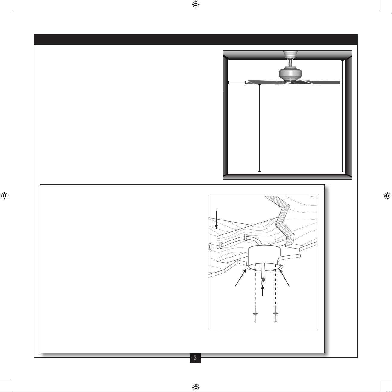
Preparing the Fan Site
Step 1 - Choose the Fan Site
Proper ceiling fan location and attachment to the building
structure are essential for safety, reliable operation, maximum
eciency, and energy savings.
Choose a fan site where:
• No object can come in contact with the rotating fan blades during
normal operation.
• e fan blades are at least 7 feet above the oor and the ceiling is
at least 8 feet high.
• e fan blades have no obstructions to airow, such as walls or
posts, within 30 inches of the fan blade tips.
• e fan is directly below a joist or support brace that will hold the
outlet box and the full weight of the fan.
30” From
Wall or
Nearest
Obstruction
7’ Minimum
Blades to
Floor
8’ Minimum
Ceiling
Height
Checklist for Existing Fan Site
If you want to use an existing fan site, complete the following checklist to
determine if the site is acceptable and safe for your new Hunter fan. If you
cannot check o every item, prepare a new fan site as described on this
page.
Fan Support System
• Fan attaches directly to building structure.
• Fan support system will hold full weight of the fan and light kit.
Ceiling Hole
• e outlet box clearance hole is directly below the joist or support brace.
Outlet Box
• e outlet box is an UL-approved octagonal 4” x 1-1/2” outlet box (or as
specied by the support brace manufacturer).
• e outlet box is secured to the joist or support brace by wood screws
and washers through the inner holes of outlet box.
• e outer holes of the outlet box are aligned with joist or support brace.
• e bottom of the outlet box is recessed a minimum of 1/16” into
ceiling.
Wiring
• e electrical cable is secured to outlet box by an approved connector.
• Six inches of lead wires extend from outlet box.
If your existing fan site is suitable, skip ahead to Section 2 • Installing the
Ceiling Plate.
3
Fan Support
System
Fan Support
System
Suitable Existing Fan Site
Outlet Box
Wiring
42724-01 • 07/01/10 • Hunter Fan Company
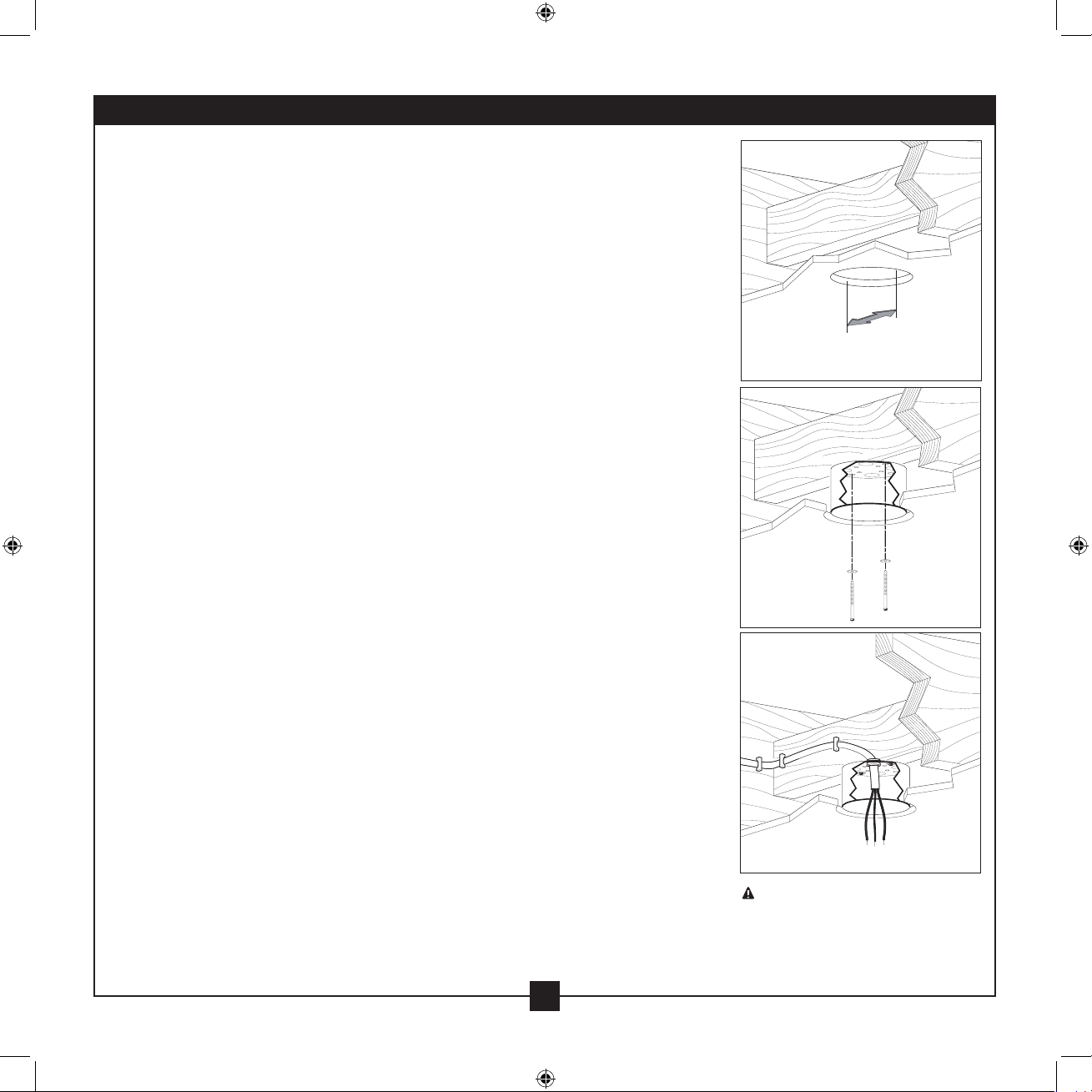
Preparing the Fan Site (continued)
Step 2 - Cut the Ceiling Hole
2-1. Locate the site for the ceiling hole directly below the joist or support brace that
will hold the outlet box and fan.
2-2. Cut a 4” diameter hole through the drywall or plaster of the ceiling. You will use
the hole to install the support brace and outlet box.
Step 3 - Install a Support Brace, If Necessary
Determine if there is a ceiling joist directly above the ceiling hole. If the joist is there,
determine if it is positioned to allow you to recess the outlet box a minimum of
1/16” into the ceiling. If NOT, install a support brace as follows:
3-1. Attach a 2” x 4” support brace between two joists. Position it to allow you to
recess the bottom of the outlet box a minimum of 1/16” into the ceiling.
3-2. Check the support brace to ensure it will support the full weight of the fan and
light kit.
Step 4 - Install the Outlet Box
4-1. Obtain a UL-approved octagonal 4” x 1-1/2” outlet box, plus two #8 x 1-1/2”
wood screws and washers, available from any hardware store or electrical supply
house.
4-2. Orient the outlet box so that both the inner and outer holes in the box align
with the joist or support brace.
4-3. Drill pilot holes no larger than the minor diameter of the wood screws (5/64”)
through the inner holes of the outlet box.
4-4. Attach the outlet box directly to the support brace or joist with two #8 x 1-1/2”
wood screws and washers. e bottom of the outlet box must be recessed a
minimum of 1/16” into the ceiling.
Step 5 - Prepare the Wiring
5-1. Make sure the circuit breakers to the fan supply line leads and associated wall
switch location are turned o . If you cannot lock the circuit breakers in the
o position, securely fasten a prominent warning device, such as a tag, to the
service panel.
5-2. read the fan supply line through the outlet box so that the fan supply line
extends at least 6” beyond the box.
5-3. Attach the fan supply line to the outlet box with an approved connector,
available at any hardware store or electrical supply house.
5-4. Make certain the wiring meets all national and local standards and ANSI/NFPA
70.
You have now successfully prepared your ceiling fan site. For instructions to install
your ceiling fan, go to your fan manual and continue with Section 2 • Installing the
Ceiling Plate.
Steps 2 – 3
Step 4
Step 5
CAUTION: All wiring must be in
accordance with national and local
electrical codes and ANSI/NFPA 70. If
you are unfamiliar with wiring, use a
qualied electrician.
4
42724-01 • 07/01/10 • Hunter Fan Company
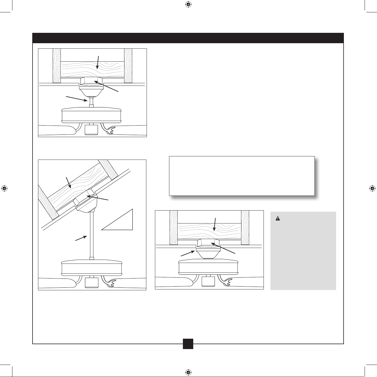
Installer’s Choice and Optional Accessories
Support Brace
Standard
Mounting
Style
Standard Mounting hangs from the
ceiling by a downrod (included).
Support Brace
Ceiling
Outlet Box
Angled
Mounting
Style
Ceiling
Outlet Box
12
Understanding Mounting and Installer’s Choice®
Hunter’s patented 3-position mounting system provides you maximum
installation exibility and ease. You can install your Hunter fan in one
of three ways, depending on ceiling height and your preference: Low
Prole, Standard, or Angled mounting. e steps in this manual include
instructions for all three Installer’s Choice mounting methods.
Considering Optional Accessories
Consider using Hunter’s optional accessories, including a wall-mounted
or remote speed control. To install and use the accessories, follow
the instructions included with each product. For quiet and optimum
performance of your Hunter fan, use only Hunter speed controls.
For ceilings higher than 8 feet, you can purchase
Hunter extension downrods. All Hunter fans use
sturdy 3/4” diameter pipe to assure stability and
wobble-free performance.
8
Low Prole
Mounting
Style
Support Brace
Ceiling
Outlet Box
CAUTION: To
reduce the risk of
personal injury, attach
the fan directly to the
support structure of
the building according
to these instructions,
and use only the
hardware supplied.
Angled Mounting recommended for a
vaulted or angled ceiling
42724-01 • 07/01/10 • Hunter Fan Company
Low Profile Mounting ts close to the
ceiling, recommended for ceilings less
than 8 feet high
5
1 • Getting Ready
To install a ceiling fan, be sure you can do the following:
• Locate the ceiling joist or other suitable support in ceiling.
• Drill holes for and install wood screws.
• Identify and connect electrical wires.
• Lift 40 pounds.
If you need help installing the fan, your Hunter fan dealer can direct
you to a licensed installer or electrician.
Gathering the Tools
You will need the following tools for installing the fan:
• Electric drill with 9/64” bit
• Standard screwdriver (magnetic tip recommended)
• Phillips-head screwdriver (magnetic tip recommended)
• Wrench or pliers
• Ladder (height dependent upon installation site)
Checking Your Fan Parts
Carefully unpack your fan to avoid damage to the fan parts. Refer to
the included Parts Guide. Check for any shipping damage to the motor
or fan blades. If any parts are missing or damaged, contact your Hunter
dealer or call Hunter Technical Support Department at 888-830-1326
(In Canada, call 1-866-268-1936).
Installing Multiple Fans?
If you are installing more than
one fan, keep the fan blades and
blade irons (if applicable) in sets,
as they were shipped.
6
42724-01 • 07/01/10 • Hunter Fan Company
 Loading...