

Hunter 20802 Owner's Manual
CAUTION!
1. Read entire instructions before beginning installation.
2. To avoid possible electrical shock, be certain electricity is
shut off at main panel before wiring.
3. All wiring must be in accordance with national and local electrical codes. If you are unfamiliar with wiring, you should use
a qualified electrician.
WARNING!
1. To reduce the risk of fire or electrical shock, do not use a solid
state speed control with this fan. Use Hunter Controls only.
2. To reduce the risk of personal injury, do not bend the blade
brackets when installing the brackets or cleaning the fan. Do
not insert foreign objects in between the rotating fan blades.
Step 1: Pre-installation Instructions
A. Select installation site. Check to see that in normal use no
object can come in contact with the rotating fan blades. The
mounting site should also meet the precautions listed in Step C
below.
B. Installation hardware is included for a standard drywall or
plaster ceiling. You will need a 4" x 1-1/2" or 4" x 1/2" outlet box
and wire nuts (2) which can be purchased from any hardware
store or electrical supply house.
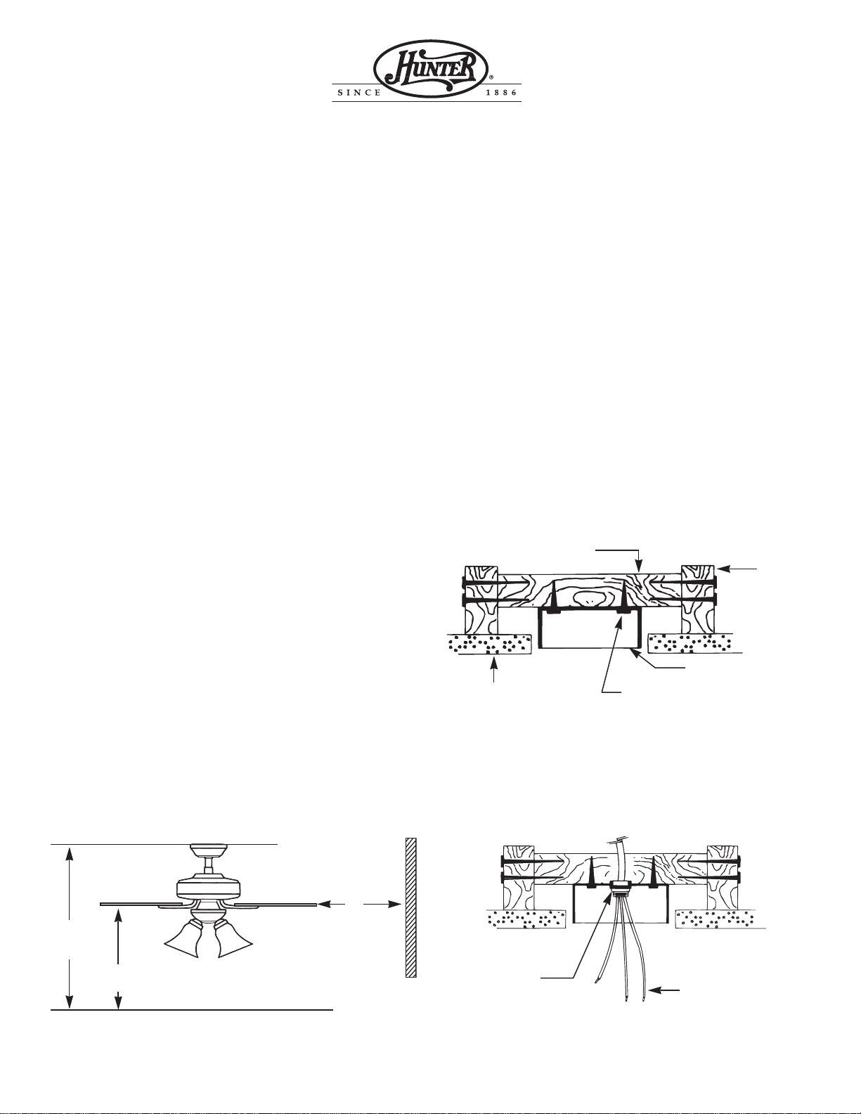
C. The fan blades must be mounted at least 7' above the floor.
For maximum efficiency, they should not have any obstruction
(walls, posts, etc.) within 24" of the blade tips. See Figure 1 for
mounting distances.
Step 2: Inspection of Fan
A. Unpack the fan carefully to avoid any damage to the
components.
B. Check for any shipping damage to the motor and the fan
blades. If more than one fan is being installed, keep the matched
and balanced blades in sets, as they were shipped. Should one of
the blades become damaged during shipment, return all blades in
the set for replacement.
C. Check contents to be certain it contains a bag of parts.
Step 3: Installation of Outlet Box and
Rough—In Wiring
CAUTION: Your Hunter ceiling fan with accessories can weigh
up to 35 lbs. The following precautions must be taken for safety
and to ensure that your fan is securely mounted to the ceiling. Be
certain electricity is “off” at the fuse panel when inspecting or
repairing installation site. All wiring must meet local and
national electrical codes. Do not mount directly to an unsupported ceiling or to an electrical outlet box. Mounting must support a 35 lb. fan with accessories.
A. Secure metallic outlet box 4" x 1-1/2" or 4" x 1/2" deep to 2
x 4 cross brace between two ceiling joists as shown in Figure 2.
The outlet box must be recessed into the ceiling by 1/16 " minimum. Secure the outlet box to the cross brace by drilling (2)
pilot holes no larger than the minor diameter of the wood screws
( 5/64") and use two #8 x 1-1/2" wood screws and washers. Use
the innermost holes for securing the box. Orient the box so the
outermost holes will be used in Step 4B.
CAUTION: Do not use lubricant on screws.
B. Bring electrical cable into the outlet box and attach with an
approved connector. Make certain that wiring meets all national
and local electrical codes. Wire leads should extend at least 6"
beyond outlet box for ease in making connections. See Figure 3.
FORM NO. 41201-01 1/95 - 1 - ©1998 HUNTER FAN CO.
INSTALLATION INSTRUCTIONS
FOR HUNTER CEILING FAN TYPE 2
READ AND SAVE THESE INSTRUCTIONS
Figure 1. Wall Clearances
Figure 3. Wiring Outlet Box
6" MIN.
LEAD LENGTH
2 x 4 BRACE
CEILING
JOIST
OUTLET BOX
CEILING
CONNECTOR
#8 WOOD SCREW &
WASHER (2) REQUIRED
Figure 2. Outlet Box
7' MIN.
TO FLOOR
24"
CLEARANCE
TO
OBSTRUCTIONS
8' MIN.
CEILING
TO FLOOR
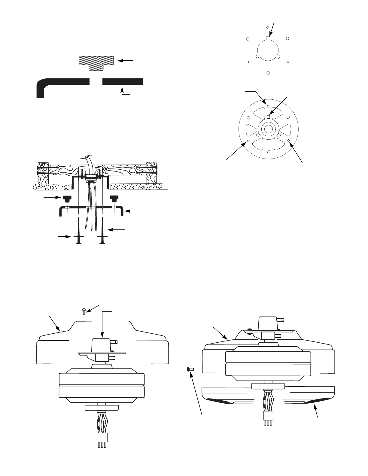
B. Before attaching the housing to the motor adaptor first align
the (3) notches in the top of the cover with the (3) matching tabs
on the adaptor.
Place the housing onto the adaptor making sure the tabs on the
adaptor fit into the notches in the housing. The housing should
sit flat on the adaptor.
Assemble the housing to the adaptor using (3) #6-32 screws with
lockwashers furnished in the sack parts. Make sure you use the
(3) screw locations located above. Tighten the screws.
C. Assemble bottom cover to fan housing using (3) #6-32
screws and lockwashers supplied in sack parts. Make certain
screws are tight (see Figure 5B).
Step 4: Installation of Ceiling Plate
A.
Install the (3) rubber bushings into the top of the ceiling
plate by inserting small side of rubber bushing into the three
round holes in the ceiling plate. See Figure 4.
B. Thread the lead wires through the opening in the ceiling
plate and install the ceiling plate to the 2 x 4 brace which supports the outlet box. Use (2) #10 wood screws 3" long and (2)
flat washers for mounting. Drill (2) pilot holes for mounting
screws 9/64" diameter. See Figure 4A.
Step 5: Fan Assembly
CAUTION: Do not lift motor by wires.
A. Assemble the fan housing to the motor hanger adaptor. See
Figures 5 and 5A.
FORM NO. 41201-01 1/95 - 2 - ©1998 HUNTER FAN CO.
RUBBER
BUSHING
CEILING PLATE
Figure 4A. Installing Ceiling Plate
Figure 5
Figure 5B
CEILING PLATE
ASSEMBLY SCREW
LOCATION (2)
ASSEMBLY SCREW
LOCATION (3)
ASSEMBLY SCREW LOCATION (1)
(3) PLACES
TAB ON TOP OF ADAPTOR
NOTCH IN TOP OF FAN HOUSING
3" WOOD SCREW
FLAT WASHER
#6-32 SCREWS
WITH LOCKWASHERS
#6-32 SCREWS
WITH LOCKWASHER
BOTTOM COVER
MOTOR HANGER ADAPTOR
HOUSING
HOUSING
RUBBER
BUSHING
Figure 4. Rubber Bushings
Figure 5A.
Top view of housing and motor hanger adaptor
showing parts alignment and assembly screws locations
 Loading...