

Hunt Electronic Outdoor Day/Night Speed Dome, Indoor SpeedDome User Manual
1
Notes on Safety
◎Please read the instructions thoroughly before installing or operating the unit.
Please do not mount the machine on an unstable surface or bracket.
Please prevent all liquids or other material from entering the dome housing.
When connecting the power source, please follow all electric safety standards and only use the power
supply designated for this device. The speed dome’s RS-485 and video signal uses TVS technology to
protect it from strong electrical surges. This technology prevents damage to the device resulting from
impulse signals such as lightning strikes or surges of power. Allow for enough distance between the
RS-485 and video signals and high-voltage equipment or cables during the transmission process. Please
do not power the unit until all connections are secure and installation is complete.
Avoid shooting very bright objects directly into the camera’s CCD (such as the sun or light fittings).
When the machine is not operating properly, please refer to the instructions for information about how to
service or repair your speed dome.
Please protect the unit against extremes of vibration, pressure or dampness while transporting unit.
Damage can occur from improperly packaging the unit while shipping.
The outdoor dome camera system is designed to be installed in outdoor environments only.
2
Ⅰ. Introduction 3
Ⅱ. Technical Data 3
2.1. Technical Parameters of the Intelligent High-speed Dome 3
2.2. Camera Parameter for High-speed Dome: (Built in SONY Camera). 4
Ⅲ. Settings 4
3.1 Dome Address, Transmission Speed, Protocol Setting 4
3.2 Speed Dome Camera Address Setting 5
3.3 Speed Dome Camera Communication Protocol Setting 6
3.4 Speed Dome Camera Transmission Speed Setting (Baud Rate Setting) 6
3.5 RS-485 Bus Matching Resistance 6
IV. Basic Function of Dome Camera 7
4.1 Preset Position 7
4.2 Dome Pattern Tours 7
4.2.1 Preset Position Parameter Setting 7
4.2.2 Pattern Tours Setting 7
4.3 Auto Scanning (Two points scanning, 360°scanning) 7
4.3.1 Two Points Scanning 7
4.3.2 360° Scanning 8
4.4 Guard Location 8
4.4.1 Setting the Guard Location 8
4.5 Alarm Linkage Function 9
4.6 Objective Tracking 9
4.7 Focus/Rotation Speed Auto Match Technology 10
4.8 Auto-Flip 10
4.9 Camera Control 10
4.9.1 Zoom Control 10
4.9.2 Focus Control 10
4.9.3 Iris Control 10
4.9.4 Auto Backlight Compensation 11
4.9.5 Auto White Balance 11
V. Camera Menu (OSD Menu) Setting 11
VI. Present Position Char Over lap Function (Multi-Function Series Only) 12
VII. Protocol Order 12
7.1 PELCO-D,PELCO-P Protocol Order Chart 12
7.2 SAMSUNG, KALATEL Protocol Order Chart 12
VIII Camera Menu of available models 13
8.1 Sony camera menu 13
8.2 LG Camera 14
8.3 CNB camera menu 16
Ⅹ. Exception Handling 20
3
. Introduction
Congratulations on purchasing our speed dome, an intelligent, high-speed dome with a
high-performance DSP camera and sophisticated zoom lens. It is an advanced technological
surveillance product combining an all-direction variable speed dome and digital decoder all in one unit.
It can aim quickly and scan continuously, making omni-directional and non-blind-spot monitoring into
reality. Additionally, it can quickly adapt to changing environments with its 18x optical and 12x digital
zoom with precise stepping motors. The advanced stepping motor technologies enable the dome to
rotate smoothly, respond sensitively and aim precisely. The speed dome camera has a memory
function so when the power cuts off it can auto resume to previous working status. Use our
high-performance speed dome “When it Counts.”
All of the features make the intelligent high-speed dome camera fit for a wide range of applications such
as intelligent building, bank, street of city, airport, station etc.
. Technical Data
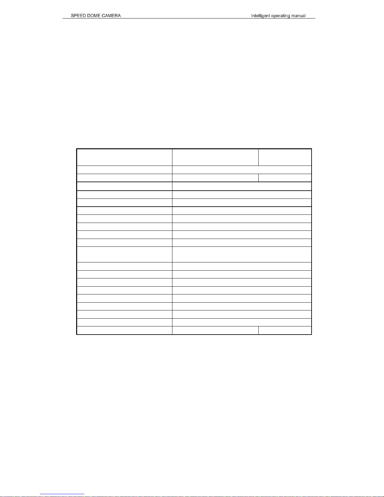
2.1. Technical Parameters of the Intelligent High-speed Dome
Model
Outdoor Day/Night
Speed Dome
Indoor Speed
Dome
Power Supply AC24V±5%
Operating temperature - 40~+60 0~+40
Operating moisture ≤95%
Power consumption 20W
Communication RS485 bus
Communication transmission speed 1200/2400/4800/9600bps
Horizontal rotation speed 0.4° - 280°(1-64 grade shift gears)
Horizontal rotation range 360° unlimited rotation
Tilt rotation range 90°
Auto f lip Rotates 180° when camera tilts to the vertical position
Auto zoom speed control Control speed auto-adjusted according to zoom length
changing
2 points scan Can set freely
2 points scan speed 1- 64 grade available
Dwell time(2 points scan) 1 - 60s available
Preset Positions 128 pcs
Running to preset speed: 1 - 64 grade available, 0.4º- 280 º
Dwell time at preset position 1 - 60s available
Cruise Tour: 8 group
Cruise Points Qty per cruise group 16 preset positions
Fan, Heater Fan and heater auto-starts 24VAC NIL
4
2.2. Camera Parameter for High-speed Dome: (Built in SONY Camera).
Model Outdoor Day/Night Speed Dome Indoor Speed Dome
Mode
¼”Sony Exview (Day/Night) CCD ¼” Sony Exview CCD
Sync Internal/ external
Scan 2:1 Interlace
Resolution >480 lines
Minimum illumination 0.7lux/0.01lux (b/w mode) 0.7lux
Iris Auto/manual
Focus Auto/manual
Zoom 216 X (Optical 18x; Digital 12x)
Focal length f=4.1-73.8mm, F=1.4-3
Angle of view 47°(wide) , 2°(Tele-)
Backlight compensation Backlight compensation
White balance Auto
Gain Auto
Signal PAL/NTSC
S/N ratio >55dB
Video signal output 1.0±0.2Vp-p
Ⅲ. Settings
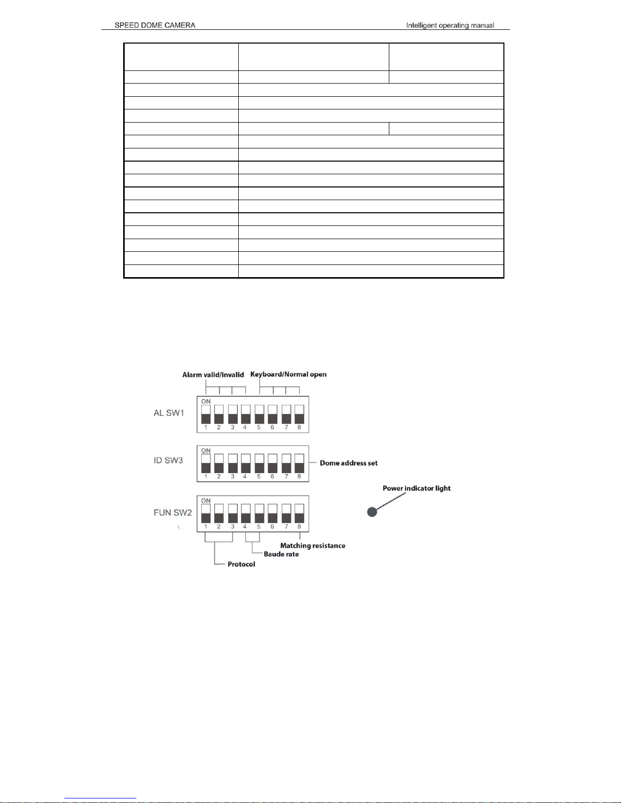
3.1 Dome Address, Transmission Speed, Protocol Setting
Before the dome is installed, the communication protocol, baud rate and dome address, should be
confirmed. Set the code switch, keeping the setting consistent with the control system. The relative
code switch site and connecting wires are diagramed below for reference.
5
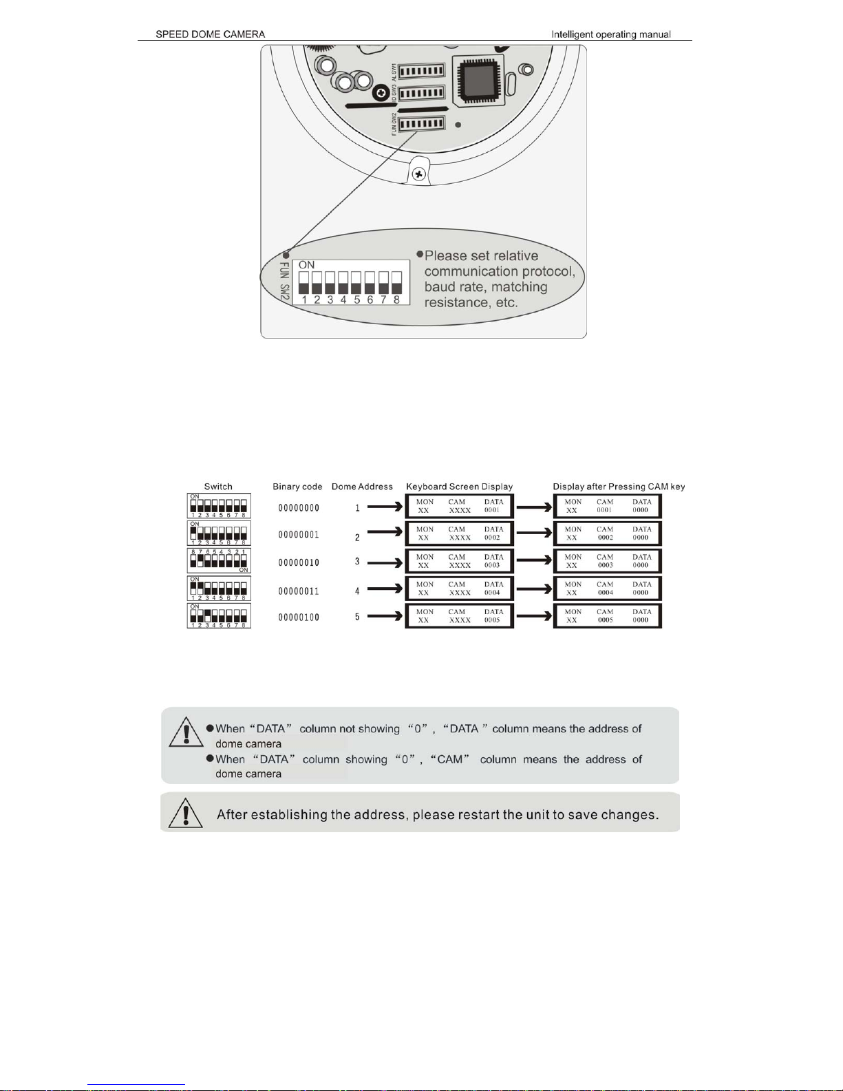
3.2 Speed Dome Camera Address Setting
The address code for the speed dome should be properly set before use to ensure accurate addressing
of the dome at the control center and to control several dome cameras. The address code is made up
of SW2 (8 bits) on PCB board. The 8 bit switch uses the 8421 binary coded decimal system. The largest
value is 256. 1 means ON status and 0 means OFF status. Each dome address code and keyboard
relative screen display mode is represented in the chart below (see the following figure and the
address/digits in following chart)
With reference to the above chart: When all code switches are under “OFF” status on speed dome,
address code is 1. When you input Numerical key No.1 on control keyboard, then press CAM key for
confirmation showing that set keyboard address as No.1 control address., At this time, keyboard can
control speed dome camera(its control address is 0001). Other addresses should be set as above.
6
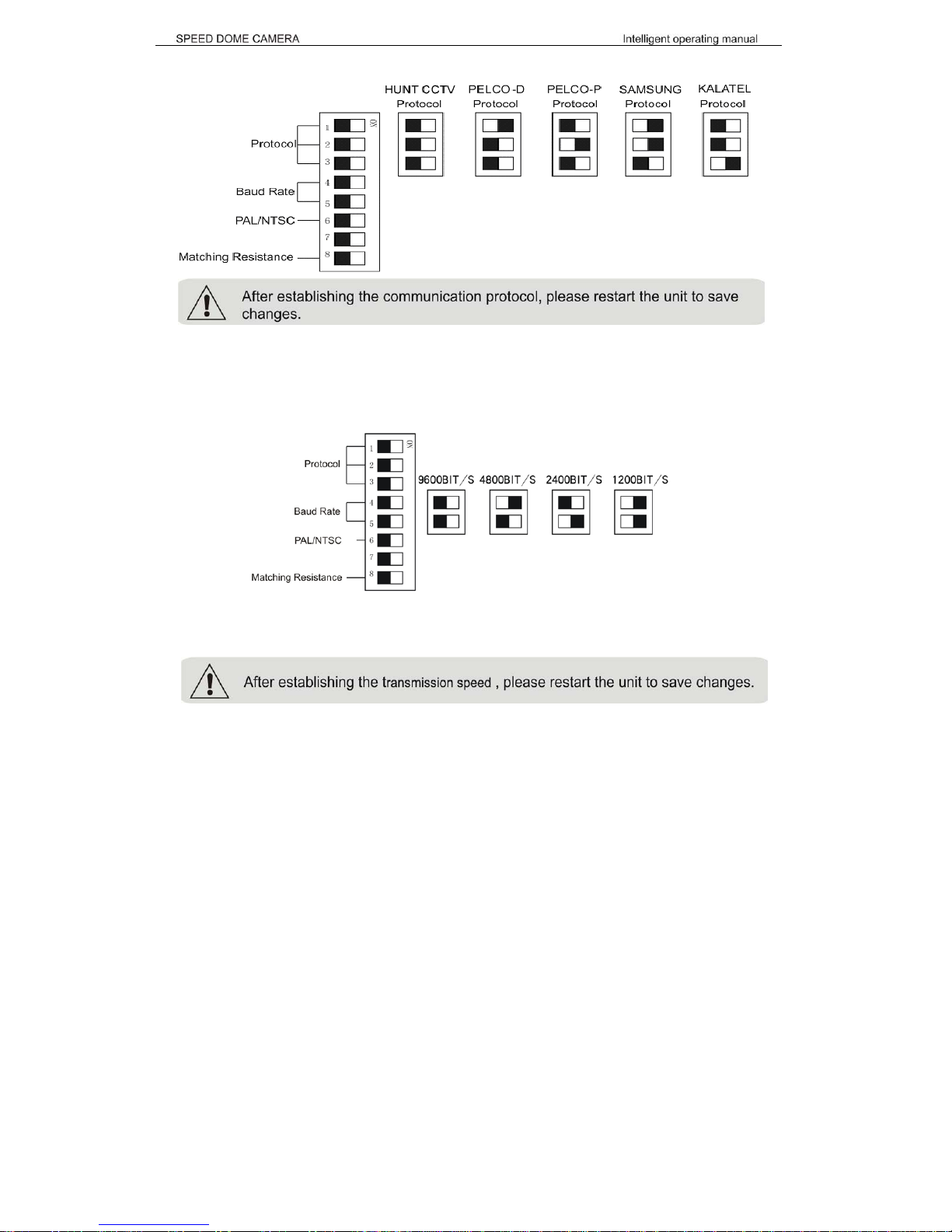
3.3 Speed Dome Camera Communication Protocol Setting
The 1st, 2nd and 3rd bits in SW3 are used to set communication protocol (see following figure)
Please ensure that the controlling device and the camera are using the same protocol.
3.4 Speed Dome Camera Transmission Speed Setting (Baud Rate Setting)
The 4th and 5th bits of SW3 on the PCB board are used to set the baud rate (see following figure). The
default baud rate setting is 9600.
Baud Rate Options: 1200BIT/S 、2400BIT/S 、4800BIT/s、9600BIT/s
Please refer to the controlling device and protocol for baud rate requirement.
3.5 RS-485 Bus Matching Resistance
For better centralized control, a matching resistance should be connected in a parallel way at the
connecting port where the RS-485 is connected into the device which is the furthest away from the
center controller. By doing this, reflection and interference from the RS-485 signal and the like can be
cleared up. There is a switcher for controlling of the matching resistance at the end of SW2 on the PCB
board. And the matching resistance is connected to the RS-485 cable when the “No. 8” switcher is set
to “ON” status.
 Loading...