

Hunt Electronic HVRM-T1600L Installation & User Manual

Installaction & User Manual
0
HVRM-T1600L
Install & User’s Guide
(v 1.0)
Installation/User Manual
HVRM-T1600M, HVRM-T800M, HVRM-T400M,
HVRM-T1600Q, HVRM-T800Q
Digital Video Recorder
Installation/User Manual
English

Installaction & User Manual
1
Introduction
Thank you for purchasing a Hunt digital video recorder.
This manual is for . Before product installation and operation, please become thoroughly familiar
with this user manual and other manuals referenced by this manual.
This user manual and the software and hardware described here are protected by copyright law.
With the exception of copying for general use within fair use, copying and reprinting the user
manual, either partially or in entirety, or translating it into another language without the consent
of Hunt Inc. is strictly prohibited.
This specification may change without prior notice for improvement of product performance.
Product Warranty and Limits of Responsibility
The manufacturer does not assume any responsibility concerning the sale of this product and
does not delegate any right to any third party to take any responsibility on its behalf. The
product warranty does not cover cases of accidents, negligence, alteration, misuse or abuse.
No warranty is offered for any attachments or parts not supplied by the manufacturer.
Malfunctions due to negligence by the user
Deliberate disassembly and replacement by the user
Connection of a power source other than a properly rated power source
Malfunctions caused by natural disasters (fire, flood, tidal wave, etc.)
Replacement of expendable parts (HDD, FAN, etc.)
※ The warranty period for the HDD and Fan is one year after purchase.
This product is not for exclusive use of crime prevention but for assistance in cases as
fire or theft. We take no responsibility for damage from any incident.

Installaction & User Manual
2
Caution
As this equipment undergone EMC registration and suitable for business purpose, distributors
and users are aware of this point.
FCC Compliance Statement
Caution : Any changes or modifications in construction of this device which are not expressly
approved the party responsible for compliance could void the user's authority to operate the
equipment.
NOTE : This equipment has been tested and found to comply with the limits for a Class A
digital device, pursuant to part 15 of the FCC Rules. These limits are designed to provide
reasonable protection against harmful interference when the equipment is operated in a
commercial environment. This equipment generates, uses, and can radiate radio frequency
energy and, if not installed and used in accordance with the instruction manual, may cause
harmful interference to radio communications, Operation of this equipment in a residential
area is likely to cause harmful interference in which case the user will be required to correct
the interference at his own expense.
Warning
This is a class A product. In a domestic environment this product may cause radio interference
in which case the user may be required to take adequate measures
Warning
1. In case of changing built-in lithum battery, it should be replaced as same or kindred one to
prevent a danger of explosion. Since old batteries could be a factor of environment
contamination, be cautios to treat them.
2. Do not throw the batteries to fire or heating. Neither short circuiut or disassembly is
prohibited.
3. Do not charge the batteries provided with Remote Controller

Installaction & User Manual
3
Important Notice
1. Do not place heavy objects on the top of the product.
2. Product is for indoor use. It is not weatherproof. Use product with referring to its
environmental specifications (Temperature & Humidity). To clean the product, gently wipe the
outside with a clean dry cloth.
3. Product uses AC power of 110V ~ 240V. Be cautious not to cause electric damages to
product.
4. Be careful not to drop the product. Physical shocks may harm the product including internal
HDD. In addition, be sure the product is secured after installation.
5. Product is made of metal. Therefore you can hurt human beings if you throw it to them or hit
on them. When installing product, be cautious to locate on safe places where children are
unreachable.
6. If Product does not operate properly, please contact the closest HUNT distributor for after
sales service. Tampering or disassembling the product will void the warranty.
7. Security surveillance laws may differ for each country. Therefore, please contact the local
region first to avoid any surveillance law violations.
Experience and technical skills are needed for the installation of this product as an improper
installation may cause fire, electric shocks, or defects. Any installation job should be performed
by the vendor you purchased this product from.
The content of this manual can differ according to firmware or Software upgrading, and the
standard and appearance of products may be changed for the improvement of quality without
an advance notice.

Installaction & User Manual
4
Contents
INTRODUCTION ............................................................................. 1
KEY FEATURES ............................................................................. 9
INSTALL MANUAL ....................................................................... 12
1. FEATURE .............................................................................. 12
1.1 Supplied Accessories ....................................................................................................... 12
1.2 Description & Function ..................................................................................................... 13
1.2.1 Front .......................................................................................................................... 13
1.2.2 Rear ........................................................................................................................... 15
1.2.3 REMOTE CONTROLLER ......................................................................................... 16
2. INSTALLATION ......................................................................... 18
2.1 Installation and Connection .............................................................................................. 18
2.1.1 Connecting & Running .............................................................................................. 18
2.2 Running OSD menu ......................................................................................................... 19
2.2.1 OSD menu configuration ........................................................................................... 19
2.2.2 Setting remote controller ........................................................................................... 21
2.2.3 Installation examples ................................................................................................. 22
2.2.4 Basic Setting ............................................................................................................. 23
2.3 Connecting and configuring DIO ports ............................................................................. 27
2.3.4 HDD ........................................................................................................................... 37
2.3.5 Remote monitor and control ...................................................................................... 38
2.3.6 External device connection ....................................................................................... 39
2.3.7 NVS04 connection ..................................................................................................... 41
USER MANUAL ............................................................................ 43
3. MENU USE ............................................................................ 43

Installaction & User Manual
5
3.1 Menu Structure ................................................................................................................. 43
3.2 Function Menu .................................................................................................................. 43
3.3 Factory Reset ................................................................................................................... 44
4. MONITORING ........................................................................ 49
4.1 Basic Screen .................................................................................................................... 49
4.2 Single Fll Screen Mode .................................................................................................... 49
4.3 Multi Screen Mode ............................................................................................................ 49
4.4 Screen Description ........................................................................................................... 49
4.5 Auto Switch Mode ............................................................................................................. 50
4.5.1 System Standard Mode ............................................................................................. 50
4.5.2 User Sequence Mode................................................................................................ 50
4.6 Event Screen .................................................................................................................... 51
4.7 Zoom Screen Mode .......................................................................................................... 52
4.8 Pause Live Screen ........................................................................................................... 52
4.9 PTZ Control ...................................................................................................................... 53
4.9.1 Pan/Tilt ............................................................................................................................ 54
4.9.2 Zoom/Focus .................................................................................................................... 54
4.9.3 Load Preset .................................................................................................................... 54
4.9.4 Save Preset .................................................................................................................... 54
4.9.5 Auxiliary On ..................................................................................................................... 54
4.9.6 Auxiliary Off ..................................................................................................................... 55
4.9.7 Menu ............................................................................................................................... 55
5.PLAYBACK ................................................................................ 56
5.1 Playback Mode ................................................................................................................. 56
5.1.1 Playback on Standard monitor (16 / 9 division) ......................................................... 56
5.1.2 Playback function ...................................................................................................... 56

Installaction & User Manual
6
5.2 SEARCH MODE ............................................................................................................... 56
5.2.1 Time Search .............................................................................................................. 57
5.2.2 Schedule Search ....................................................................................................... 57
5.2.3 Event Search ............................................................................................................. 58
5.2.4 Thumbnail Search ..................................................................................................... 58
5.3 Copy ................................................................................................................................. 59
5.3.1 CD/DVD ..................................................................................................................... 59
5.3.2 RE4............................................................................................................................ 61
5.3.3 AVI ............................................................................................................................. 61
6.CONFIGURATION ..................................................................... 63
6.1 Recording Structure .......................................................................................................... 63
6.2 System Setup ................................................................................................................... 63
6.2.1 Date/Time .................................................................................................................. 63
6.2.2 Disk............................................................................................................................ 66
6.2.3 User Setup ................................................................................................................ 68
6.2.4 Utility .......................................................................................................................... 70
6.3 Network............................................................................................................................. 73
6.3.2 xDSL .......................................................................................................................... 75
6.3.3 WRS .......................................................................................................................... 75
6.4 Device Setup .................................................................................................................... 76
6.4.2 Camera Setup ........................................................................................................... 76
6.4.3 Monitor Setup ............................................................................................................ 77
6.4.4 Audio Setup ............................................................................................................... 79
6.4.5 Text Setup ................................................................................................................. 80
6.4.6 Serial Setup ............................................................................................................... 81
6.5 Event Setup ...................................................................................................................... 82
6.5.2 Event Check .............................................................................................................. 83
6.5.3 Sync Event ................................................................................................................ 84
6.5.4 Motion Detection ....................................................................................................... 85
6.5.5 Sensor ....................................................................................................................... 87
6.5.6 Preset ........................................................................................................................ 87

Installaction & User Manual
7
6.6 Recording setup ............................................................................................................... 88
6.6.2 Program setup ........................................................................................................... 88
6.6.3 Manual/Schedule recording setup ............................................................................. 89
7. WEB VIEWER ........................................................................... 95
7.1 System requirement ......................................................................................................... 95
7.2 Login ................................................................................................................................. 95
7.3 User Setup ........................................................................................................................ 96
7.4 Browser available ............................................................................................................. 97
7.5 Monitor .............................................................................................................................. 97
7.5.1 Screen division and changing video position ............................................................ 97
7.5.2 Move to Playback ...................................................................................................... 98
7.5.3 Channel On/Off ......................................................................................................... 99
7.5.4 Sensor Indication ....................................................................................................... 99
7.5.5 Relay operation ......................................................................................................... 99
7.5.6 Using Microphone ..................................................................................................... 99
7.5.7 Event Data ............................................................................................................... 100
7.5.8 Video Recording & Save Saving ............................................................................. 100
7.5.9 Using PTZ ............................................................................................................... 101
7.5.10 Using Audio ............................................................................................................. 102
7.5.11 Closing Video Channel ............................................................................................ 102
7.6 Playback ......................................................................................................................... 103
7.6.1 Video Division & Changing Channel ....................................................................... 103
7.6.2 Image recording ...................................................................................................... 103
7.6.3 Print ......................................................................................................................... 104
7.6.4 Backup .................................................................................................................... 104
7.6.5 Web Monitor ............................................................................................................ 105
7.6.6 Channel On/Off ....................................................................................................... 105
7.6.7 Saving time & Checking Rec, Capacity ................................................................... 105
7.6.8 Searching Calander................................................................................................. 105
7.6.9 Functional function at the buttom of monitor ........................................................... 106
8. USER MANUAL FOR MOBILE VIEWER ............................ 107

Installaction & User Manual
8
8.1 Log-In page..................................................................................................................... 107
8.2 Monitoring page .............................................................................................................. 107
TROUBLE SHOOTING ............................................................... 109
THE WAY TO CHECK THE MANUFACTURING DATE ............... 111
AVAILABLE HDD ......................................................................... 112
COMPATITABLE CD/DVD LIST ................................................... 112
SPECIFICATION .......................................................................... 112
PRODUCT DIMENTION ............................................................... 115

Installaction & User Manual
9
KEY FEATURES
Monitoring Screen
Supprots real live video with high resolution per each channel and variable display mode.
Real H.264 Video
Various monitoring
Single, 4ch, 9ch, 10ch, 16ch
Auto Switching(AUTO)
Composite 4 ea, DVI 2ea
Audio Recording
Supprots real-time audio input and recording
Simultaneous 16ch audio input & recording available
Input : 4ch RCA, 12ch D-SUB, Output : 1ch(Rear)
Simultaneous audio recording and playback available
Recording
It supports 480ips recording at H.264 High-Resolution (4CIF) and available to record max.
5 seconds before triggering an event. Also, convert function is available protecing
privacy(Covert func.).
H.264 Video recording with High-Quality
D1(720x480) 480ips
Supports manual & schedule recording
Video loss detection
Supports archiving event list (Sensor, Video loss, Motion detection, Text)
Available record Max 5 seconds before triggering an event per each channel

Installaction & User Manual
10
Search / Playback
It supports variable and convenient functions for search & playback.
Play back by time,date,channel
Easy and convenient search using mouse
Pre/Post search from a freeze frame
Play back by Event (Sensor, Video Loss, Motion Detection, Text)
Easy search by Remote controller
Back up device
It is available to back up to DVD-R,CD-R,USB memory by user‟s choice
Supports various back up device : DVD-R, CD-R, USB, 1394b
HDD external unit (recordin unit for external capacity expension)
Network
It supports variable network like LAN, XDSL and easily control from remote site using PC
cliet viewer.
E-mail notification thru, TCP/IP, DHCP in case of triggering an event
Live monitoring form remote site (Whole screen or available to select quad
screen)
Available to playback, recording, search and DVR management thru. network
viewer in PC
Available to record, search & playback by time from remote site.
Supprots 10/100Mbps Ethernet/xDSL
ETC
Multiple DVR connection
Supports User friendly GUI and mouse function

Installaction & User Manual
11
Supports User friendly GUI and mouse function
Easy and simple firmware upgrade thru. USB memory
PTZ Control (SPEED DOME), PRESET fucntion
Available to control up to 16 DVRs with one remote controller
Installaction & User Manual
12
Install Manual
1. Feature
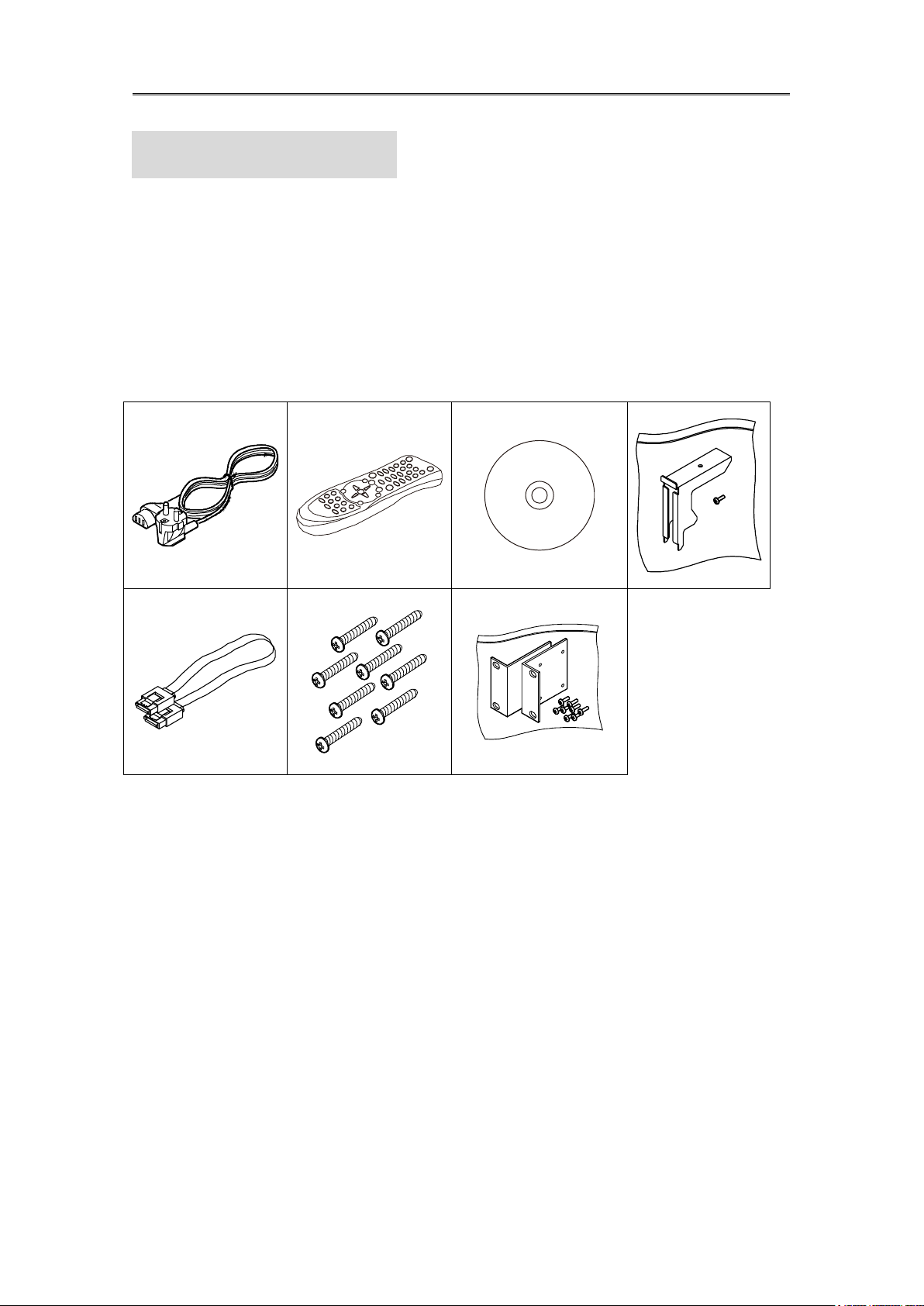
1.1 Supplied Accessories
Unpack and check all the items as below
AC Cord, Remocon, Setup CD, HDD Fixing Clamp, SATA Cable, HDD Fixing Screw, Rack
Mount
Installaction & User Manual
13
4 532
1 6 15 8 1 0
7 913 16 14
12
11
구분
기능
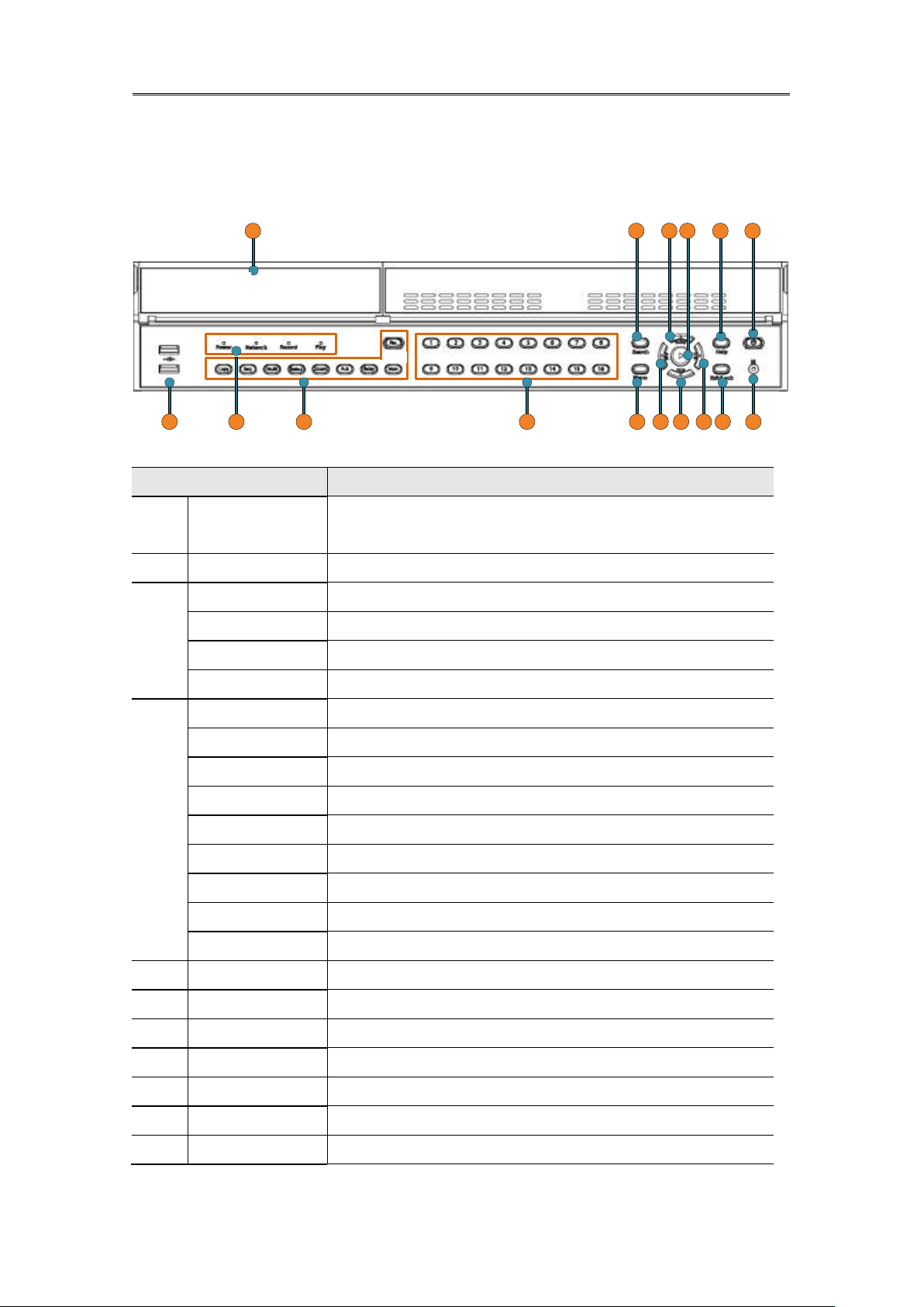
1
DVD-Multi for
Back up
Back up use for recorded data by DVD/CD media
2
USB Port
Use connecting USB memory or Mouse
3
Power LED
Display Power status
Network LED
Display network status
Recording LED
Display recording status.
Playback LED
Display playback status.
4
Copy
To run copy mode.
Sequence
To run or stop user sequence.
Multi
To change DVISION in live or playback mode.
Select
To run PTZ control panel
Zoom
To run digital zoom in live screen upto x2.
Ack
Stop buzz of event action
Relay
To run and pause Relay action by manual.
Mon
Swiching monitor
Rec
To start and stop recording
5
Channel
To select the channel.
6
Search
To enter Search mode.
7
Menu
To enter Menu
8
Help
To enter Function mode.
9
Exit
To exit menu or close pop-up window.
10
Power button
Power on/off
11
IR
Remote controller receiving sensor
1.2 Description & Function
1.2.1 Front

Installaction & User Manual
14
12
Enter/Play
To select menu or enter playback mode.
13
◀ /REW
To move or select in menu and change replay speed to
reverse direction in playback mode
14
▶ /FWD
To move or select in menu and change replay speed to
forward direction in playback mode.
15
▲/Pause
To move or select in menu and pause live/ replay video.
16
▼/Stop
To stop replay in playback mode.
Installaction & User Manual
15
2
17
31
16 15 14 13 12 1 1 10 9 8
4 5 6 7
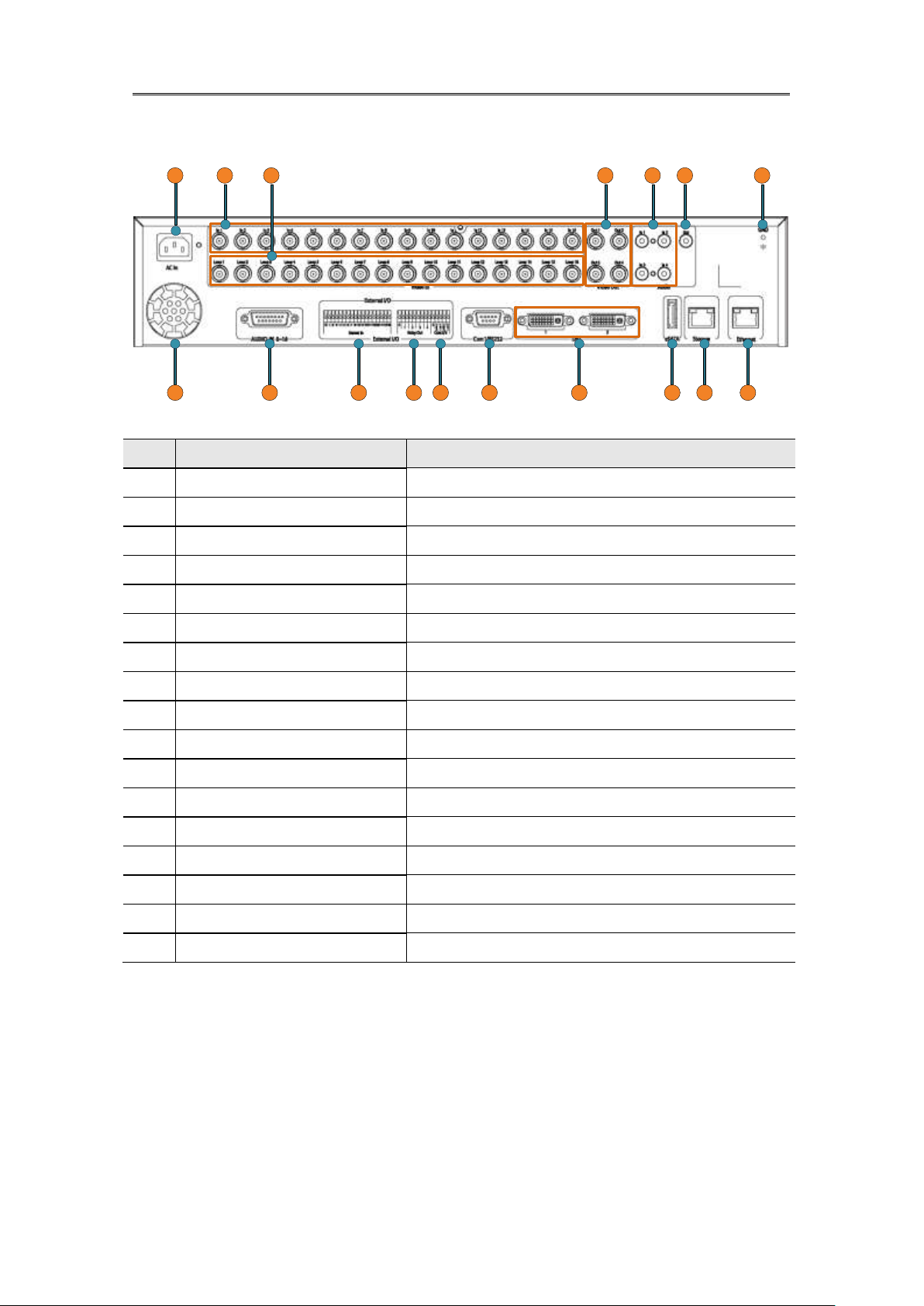
No
Input/ Output name
Descrtiption
1
Power connector
Socket for AC100V~AC240V power cord.
2
CH1~16
BNC input for camera connection
3
Loop out
BNC output(Loop) for camera connection.
4
Monitor 1~4
BNC connection for monitor output.
5
Audio input(RCA)
RCA connection for Audio input
6
Audio output
Speaker output terminal.
7
Ground
Ground between DVR & external device.
8
Ethernet
For network connection (RJ-45)
9
Storage
For external HDD connection
10
eSATA port
For eSATA external HDD connection
11
DVI OUTPUT 1,2
Vidoe output port to connect PC monitor.
12
Com1
RS-232C D-SUB.
13
Com2,3
For RS-485.
14
Relay
Relay Connection terminal.
15
Sensor IN
Input for external sensor.
16
D-Sub Audio port
D-Sub port for Audio
17
Fan
Exhaust internal heat out
1.2.2 Rear
Installaction & User Manual
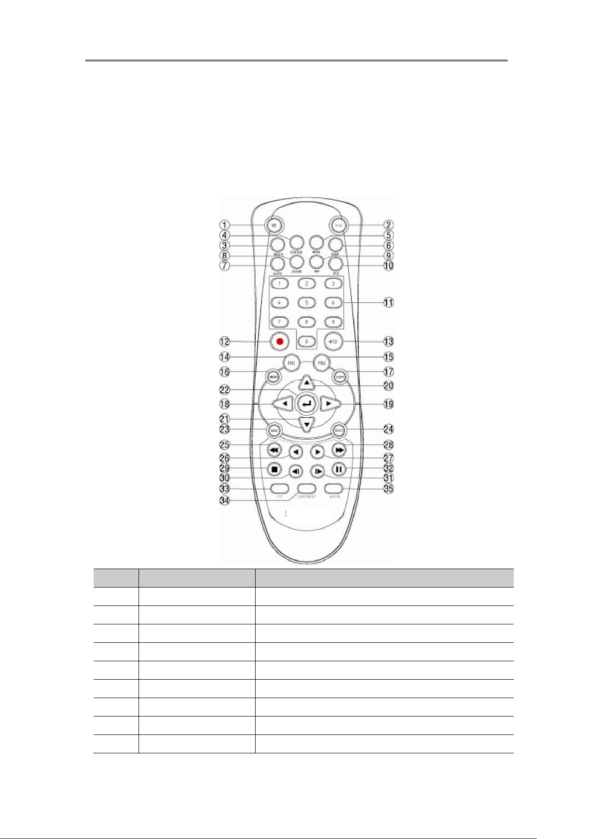
16
No.
Iten
Description
1
ID
To select Remote Controller ID
2
LOCK
Not use
3
COPY
To indicate copy menu, copy recorded data to USB
4
BACKUP
Not use
5
RELAY ON
To manually ON
6
RELAY OFF
To manually OFF
7
SEQ
Auto sequencing
8
MULTI
To change division
9
ZOOM
To run digital zoom
1.2.3 REMOTE CONTROLLER
It is available to use all functions of DVR. If several DVR are set with unique ID numbers,
they can be controlled with one remote controller. To use remote controller, it is necessary
to set ID first which want use. Keep pressing ID button repetedely (Up to Max. 16 times)
and use it matching DVR & ID.

Installaction & User Manual
17
10
SEARCH
To indicate search menu
11
CHANNEL BUTTON
To select channel
12
SELECT
Not use
13
+10
In case of selecting over 10
(+10 + 1)
14
FN1
Not use
15
FN2
Not use
16
MENU
Covert to menu screen
17
HELP
Not use
18
◀ /REW
Move setting menu to left direction/REW
19
▶ /FWD
Move setting menu to right direction/FWD
20
▲/PAUSE
Move setting menu to top direction/PAUSE
21
▼
Move setting menu to bottom direction/STOP
22
ENTER/PLAY
Menu selection/Playback
23
ENTER
To select menu
24
EXIT
To cancel setting, escape from menu
25
FAST REWIND(◀◀)
Speedy replay to reverse direction
26
REWIND PLAY(◀ )
Replay to reverse direction
27
FORWARD PLAY(▶ )
Repleay to forward direction
28
FAST FORWARD (▶▶)
Speedy replay to forward direction
29
STOP( )
To stop replay
30
STEP REVERSE(◀ l)
Replay to reverse direction by each frame
31
STEP FORWARD (l▶ )
Replay to forward direction by each frame
32
PAUSE(ll)
To freeze playback
33
P/T
PAN/TILT Control
34
LOAD PRESET
To read preset
35
AUX ON
Auxiliary ON
Installaction & User Manual
18
2. Installation
2.1 Installation and Connection
2.1.1 Connecting & Running
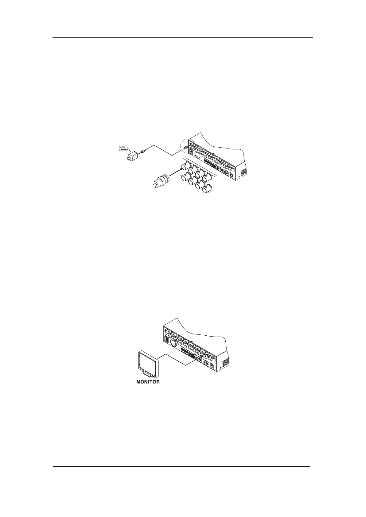
2.1.1.1 Connecting camera
Connect CCTV camera to DVR with BNC cable as below.
- The video type for all channels should be either NTSC or PAL, not be combined both
- DVR sets video signal‟s impedance (75Ω) automatically. Impedence is set as 75 Ω basically. If
connecting a dvice to video output, impedance will be “Hi-z” status.
- Video Type (NTSC/PAL) should be changed after booting DVR. The order of camera
recognition follows ch1 through Ch16 camera amd 1st recognized camera type leads other
camera type.
2.1.1.1 Connecting monitor
Connect CCTV monitor to DVR with BNC cable as below.
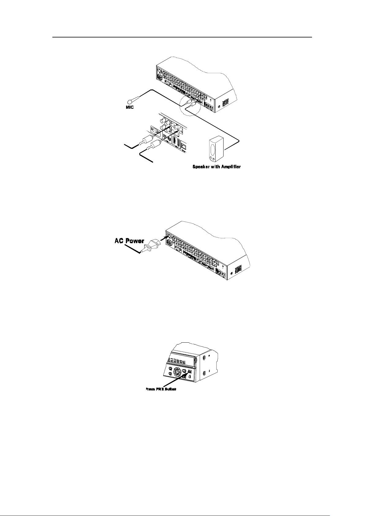
2.1.1.2 Connecting Audio
Connect audio signal to DVR with using RCA cable or D-SUB as below.
Installaction & User Manual
19
2.1.1.3 Supplying Power
Connect power cable as below.
- When supplying power, DVR starts booting automatically.
- In order to cut off power, press power switch on DVR front during 5 seconds, then select
“YES” after appearing a pop-up window.
- For supplying power again, push the Power button.
2.2 Running OSD menu
2.2.1 OSD menu configuration
Press [MENU] in keypad of front to open configuration menu as below
Installaction & User Manual
20
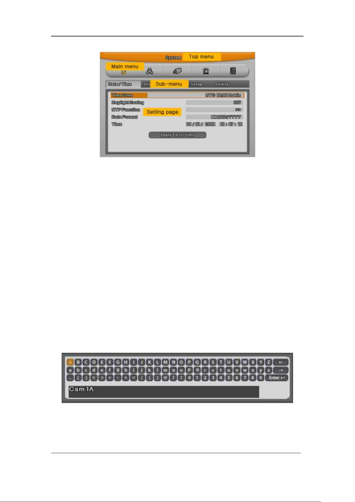
(1) Main Menu : The selected tab is show in bright color and the related sub-menu will be
shown left- below the tab. To move to the previous/next tab, use the [◀ /▶ ] arrow buttons. To
move to a sub-menu press the [Enter] key.
(2) Sub-menu : The selected sub-menu is shown as tab title and the related setting will be
shown. To move to the previous/next tab, use the [◀ /▶ ▲/▼] arrow buttons. To move to the
related setting press [Enter]. To move to upper main menu, press [ESC] button.
(3) Setting page : The selected tab is shown as orange, To move to the previous/next tab, use
the [◀ /▶ ] or [▲/▼] arrow button and press [Enter] key for value setting. Whn setting value is a
word, a dialogue box to edit the word will be open. When setting value is number, it should be
set with using [◀ /▶ ] or [▲/▼]. Press [ESC] button when the value is set and also [ESC] button
is available to upper sub-menu..
2.2.1.1 Dialogue box to edit a word
Dialogue box to edit a word is image shown as below; It is available to input both word and
bumber.
Keep pressing [▲/▼], [◀ /▶ ] arrow button until the word is looking for and press Enter. In case of
deleting input word press [], spacing words press [] button. To exit from dialogue box, press
[Enter] after finishing word input.
Installaction & User Manual
21
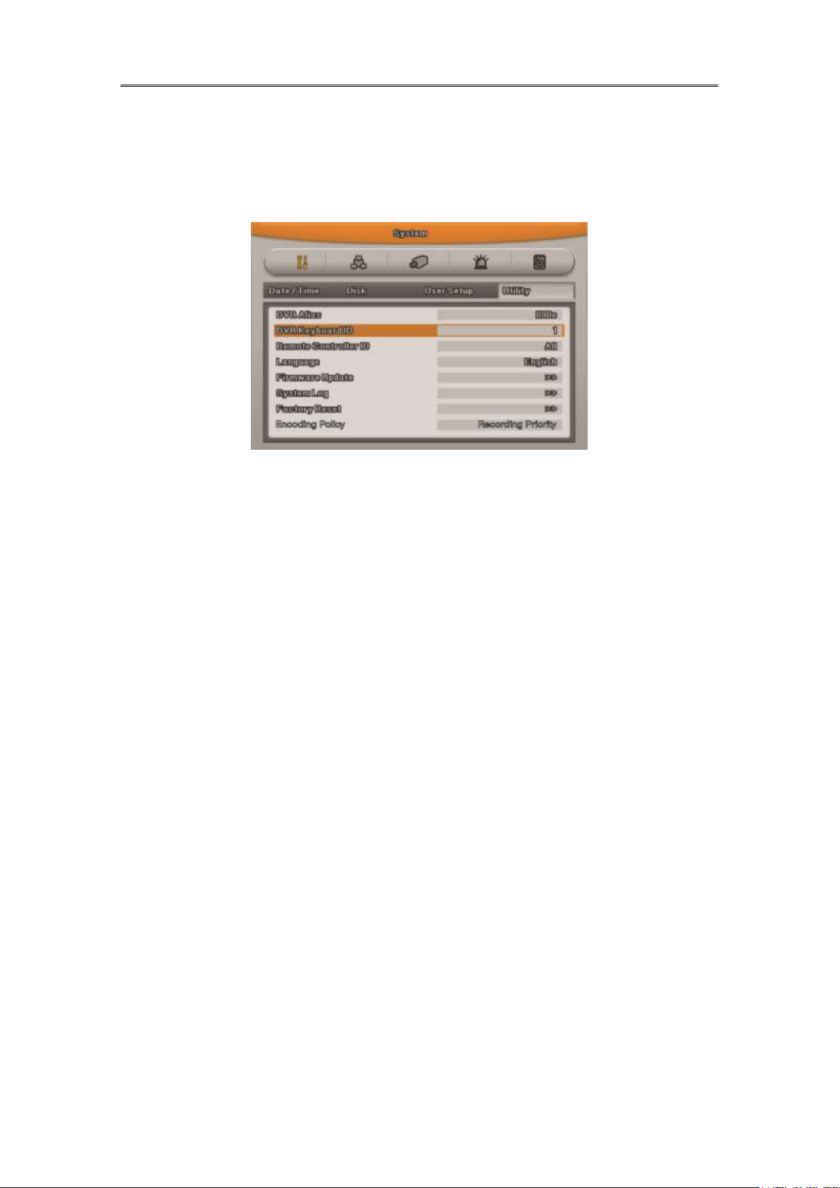
2.2.2 Setting remote controller
2.2.2.1 Setting ID of DVR
When controlling several DVRs with one remote controller, set Remote Control ID as follws.
(1) Press the [MENU] button
(2) [▶ ] Select “system” with using [▶ ] arrow button and press [Enter] or [▼] button
(3) [▼] Select “Utility” with using [▶ ] arrow button and press [Enter] button.
(4) Select “Remote Control ID” and press [Enter]
(5) [◀ /▶ ] Select a value using [◀ /▶ ] arrow buttons and press [ESC]
(6) Press the [ESC] button to return to the monitor mode.
<Reference>
Up to 16DVRs can be controlled with a single remote controller.
When not using remote controller, set the Remote Control ID as “Off”
2.2.2.2 Setting ID
If several DVRs are with unique ID numbers, they can be controllerd with one remote controller.
To select a specific DVR, keep pressing the ID button of remote controller until a buzzer sounds
during 2 seconds.
Installaction & User Manual
22
1. Remove the batter cover.
2. Taking care the poles (+/-)
are correctly positioned
3. Replace the batter cover.
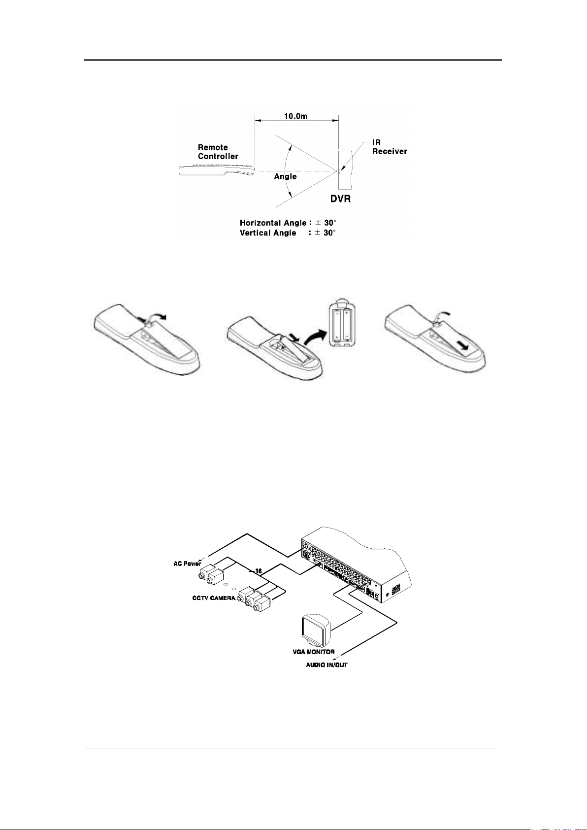
2.2.2.3 Operable range of remote controller
2.2.2.4 Loading the batteris into the remote controller
Remote controller required two AAA-type batteries. Please, refer the following installation step.
2.2.3 Installation examples
2.2.3.1 Basic configuration
Connect camera and monitor and Audio.
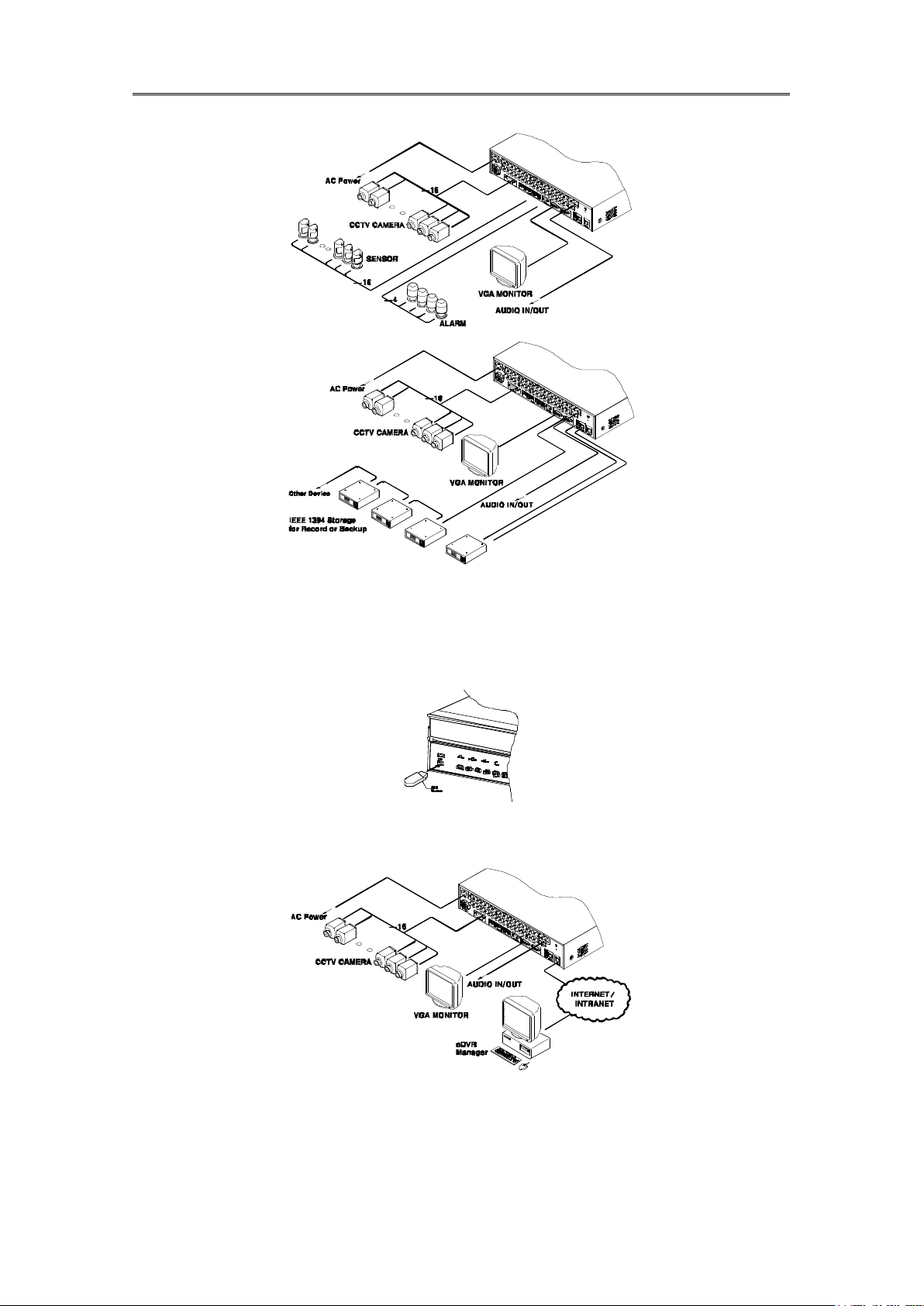
2.2.3.2 Advanced configuration
Connect camera, monitor , audion, sensor, realy etc..
Installaction & User Manual
23
2.2.3.3 External storage & back up configuration
Use USB for back up.
2.2.3.4 Internet / Intranet configuration
2.2.4 Basic Setting
Installaction & User Manual
24
2.2.4.1 Viewing Image
When power is on, eDVR starts automatically and displayed in basic 16ch-split screen after
booting.
<Reference>
If user password is set, a prompt for entering the password will be appeared. Factory
default is reserved as not responding keypad on DVR front (It is not from factory default)
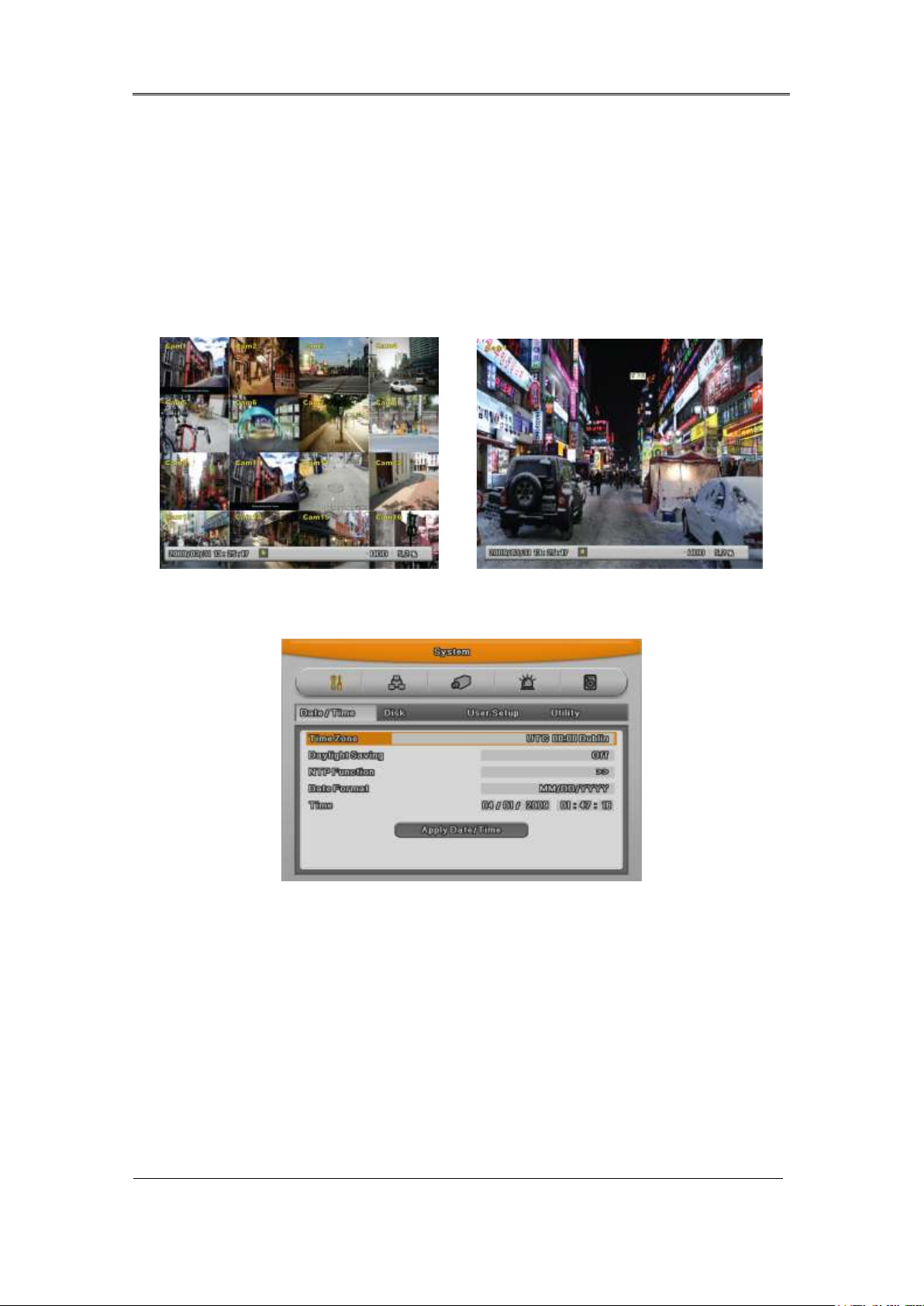
2.2.4.2 Setting Date & Time
- Press [MENU] button and select “ System” when OSD menu is appeared.
- Select“Date/Time”and press [Enter] button.
Time Zome
(1) Select “Time Zone” using [◀ /▶ ] or [▲/▼] arrow button and press [Enter] button.
(2) [◀ /▶ ] Select “Time Zone” using [◀ /▶ ] arrow button and press [ESC] button.
DAYLIGHT SAVING
(1) Summer Time is only activated for Time Zine that uses Daylight savings.
(2) Select “Daylight Saving”using [◀ /▶ ] or [▲/▼] arrow button and press [Enter] button.

Installaction & User Manual
25
(3) Select On/Off using [◀ /▶ ] arrow button and press [ESC] button.
NTP
(1) Select yes or no of using NTP.
(2) Select NTP mode among Client, server, Both using directional key. [◀ /▶ ] or [▲/▼]
(3) Select Public or Both.
(4) Enter server IP address when configuring server type by Local.
(5) Configure communication interval with server.
DATE FORMAT
(1) Select “Date Format” using [◀ /▶ ] or [▲/▼] arrow button and press [Enter] button. Select a
value using [◀ /▶ ] arrow button from YYYY/MM/DD, MM/DD/YYYY, DD/MM/YYYY.
(2) Press [ESC] after finshing value setting.
TIME
(1) Select “Time” using [◀ /▶ ] or [▲/▼] arrow button and press [Enter] button.
(2) Select Date, Time using [◀ /▶ ] arrow button and set value using [▲/▼] arrow button.
(3) Press [ESC] after finshing value setting..
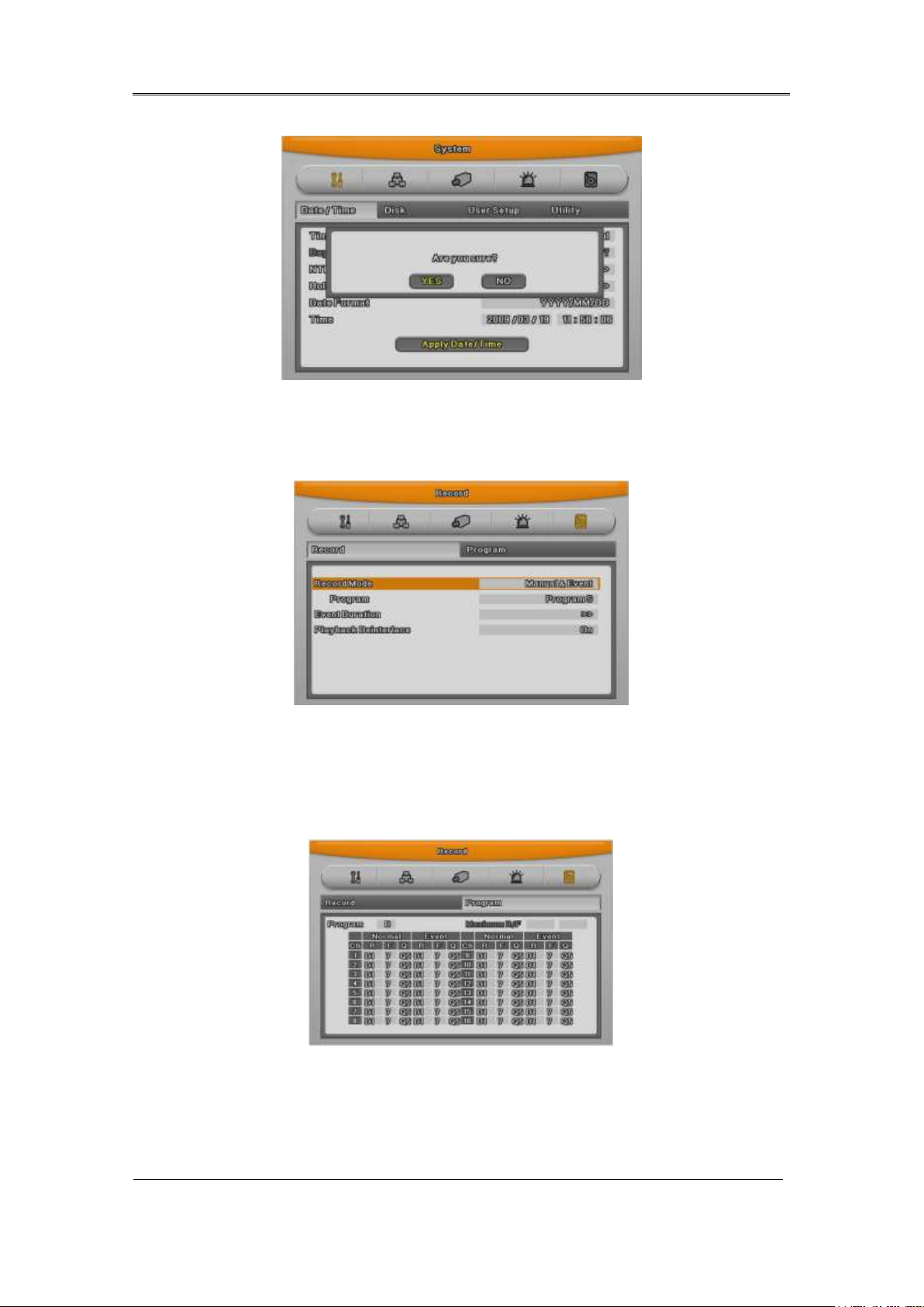
APPLY
Most setting values are appled automatically, when exiting form the related menu page. But
“Date” & “Time” setting are not applied automatically because they may critically affect the file
system of the recorded HDD. To apply Date/ Time settings confirm with [Apply Date/Time]
buttons.
(1) Select “Apply Date/ Time” using [◀ /▶ ] or [▲/▼] arrow button and press [Enter]. Then, a
warning message will be appeared as below image;
(2) Select using [◀ /▶ ] or [▲/▼] arrow button and select “YES”, then, press [ENTER] button. To
cancel, press [ESC] button.
Installaction & User Manual
26
2.2.4.3 Record Setting
Select “Record” pressing menu button in front.
Program Setting
Set resolution, frame rate, quality by each channel that user want record in “Program” of record
menu
Schedule Setting
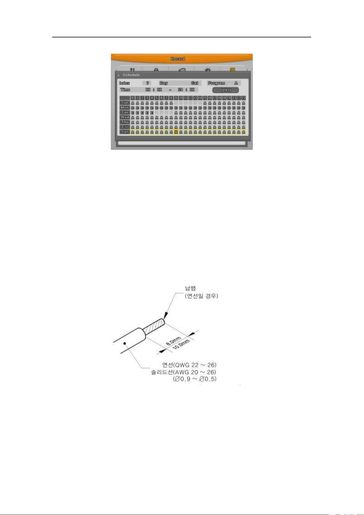
Installaction & User Manual
27
Set recording mode as “Scheduel & Event” and set by date/ time.
Checking method for recording
<Reference>
If recodrding setting is finished correctly, “REC LED” in front is flickering. In addition, it is marked
[S] indicating that all channels are recroding.
2.3 Connecting and configuring DIO ports
2.3.1 Wire Handlin
When connecting a wire to a terminal block, follow the instruction below. Not the different types
of wire that can be used.
- Standard wire : Pie off the wiring cover 8~10mm and solder it. Wire gage should AWG
22~26.
- Sold wire : Peel off the wiring cover 8~10mm and solder it.Wire gage should be AWG 20~26.
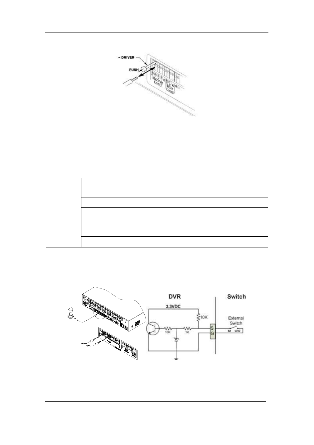
2.3.2 Inserting & removing wire
To insert & remove wire in Terminal Block, use a screw driver in the diagram like below.
Installaction & User Manual
28
Spec
Input Ch
16EA Transistor input
Input type
N.C, N.O supprt
Supported sensor
Dry contact sensor
Way of connecting
Connecting the trimmed wire to terminal block
Performance
Available input
pulse range
Minimum 500ms
Output current
Typical DC 12mA
2.3.3 Conneting and configuaring sensor
2.3.3.1 Specification
In order to run sensor input DVR normally, the following conditions are required.
Connecting sensor input
Connect S1 ~ S16 with referring the following image. It shows to connect a dry contact (Please
refer “Wire Handling”.

Installaction & User Manual
29
SPEC
Output Ch.
2EA relay outputs
Output type
Dry contact
Connecting type
Connect the trimmed wire to terminal block
Perfromance
DC
30V 1A
AC
125V 0.5A
Setting Sensor
(1) Press [Menu] button and select “Event” when OSD menu is appeared.
(2) Move to sub menu pressing [Enter] or using [▼] button and select [Enter].
All Sensor
It is used when setting for all sensors and set Off, or Normal Open (N.O.) / Normal Close
(N.C.) type.
(1) Select All and set type.
Each sensor
It is used when setting for each sensor and set selecting each sensor.
(1) Select sensor and press [Enter] button.
(2) Select sensor that user want set and set type.
(3) Press [ESC] after finishing value setting.
2.3.3.2 Connecting relay and stting
Specification
In order to run relay output of DVR normally, the following conditions are required.
Connecting relay out
Connect R1 ~ R4 with referring to the following images, it shows to connect a warning light.
 Loading...