

Hunt Electronic HVR-04 Installation Manual

HVR-04
Installation Guide
(v 3.1)

FCC Compliance Statement
Caution : Any changes or modifications in construction of this device which are not expressly
approved the party responsible for compliance could void the user's authority to operate the
equipment.
NOTE : This equipment has been tested and found to comply with the limits for a Class B digital
device, pursuant to part 15 of the FCC Rules. These limits are designed to provide reasonable
protection against harmful interference in a residential installation. This equipment generates, uses
and can radiate radio frequency energy and, if not installed and used in accordance with the
instructions, may cause harmful interference to radio communications, However, there is no guarantee
that interference will not occur in a particular installation. If this equipment does cause harmful
interference to radio or television reception, which can be determined by turning the equipment off
and on, the user is encouraged to try to correct the interference by one or more of the following
measures:
- Reorient or relocate the receiving antenna.
- Increase the separation between the equipment and receiver.
- Connect the equipment into an outlet on a circuit different from that to which the receiver is
connected.
- Consult the dealer or an experienced radio/TV technician for help.
CAUTION
1. Danger of explosion if battery is incorrectly replaced. Replace only with the same or equivalent type.
2. Disposal of used batteries according to the general recommendations against the environmental
pollution.
3. Do not throw the batteries into a fire, and do not heat, short-circuit or attempt to disassemble the
batteries.
4. Do not attempt to recharge the batteries.

Important Notice
1. Do not place heavy objects on the top of the HVR-04.
2. HVR-04 is for indoor use. It is not weatherproof. Use HVR-04 with referring to its environmental
specifications (Temperature & Humidity). To clean the HVR-04, gently wipe the outside with a clean dry
cloth.
3. Be sure to use a DC adapter that is provided by Web Gate Inc. Connecting HVR-04 directly to an AC
current will cause electric damages to HVR-04.
4. Be careful not to drop the HVR-04. Physical shocks may harm the product. In addition, be sure the
HVR-04 is secured after installation.
5. HVR-04 is made of metal. Therefore you can hurt human beings if you throw it to them or hit on them.
When installing HVR-04, be cautious to locate on safe places where children are unreachable.
6. If HVR-04 does not operate properly, please contact the closest HUNT ELECTRONIC distributor for
after sales service. Tampering or disassembling the product will void the warranty.
7. Security surveillance laws may differ for each country. Therefore, please contact the local region first
to avoid any surveillance law violations.

Contents
OVERVIEW...................................................................................................................................7
1. What is HVR-04? ..................................................................................................................7
2. Supplied accessories .......................................................................................................... 8
3. Description & Function........................................................................................................9
INST ALLA TI ON AND CONNECTION......................................................................................... 11
4. Connecting & Running HVR-04........................................................................................ 11
4.1. Connecting camera....................................................................................................... 11
4.2. Connecting monitor....................................................................................................... 12
4.3. Connecting audio..........................................................................................................12
4.4. Supplying power ........................................................................................................... 13
5. Running OSD menu...........................................................................................................14
5.1. Using menu...................................................................................................................14
5.2. Dialogue box to edit a word..........................................................................................15
6. Setting remote controller .................................................................................................. 16
6.1. Setting remote control DIP switch.................................................................................16
6.2. Set ID of HVR-04..........................................................................................................16
6.3. Selecting HVR-04 ......................................................................................................... 17
6.4. Operable range of remote controller............................................................................. 17
6.5. Loading the batteries into remote controller.................................................................18
7. HVR-04 configuration ........................................................................................................ 19
7.1. Basic configuration........................................................................................................19
7.2. Advanced configuration................................................................................................19
7.3. External storage & Backup configuration......................................................................20
7.4. Internet/Intranet configuration.......................................................................................20
8. HVR-04 basic setting ......................................................................................................... 21
8.1. Viewing image...............................................................................................................21
4

8.2. Setting Date & Time...................................................................................................... 22
8.2.1. Time zone..............................................................................................................22
8.2.2. Daylight saving ...................................................................................................... 22
8.2.3. Time format............................................................................................................22
8.2.4. Date.......................................................................................................................23
8.2.5. Time ....................................................................................................................... 23
8.2.6. Apply Date/Time.................................................................................................... 23
8.3. Setting recording condition...........................................................................................24
8.3.1. Configuration status...............................................................................................24
8.3.2. Channel status.......................................................................................................25
8.3.3. Recording speed/quality........................................................................................25
8.3.4. Speed(ips)..............................................................................................................25
8.3.5. Quality....................................................................................................................25
8.3.6. Audio recording......................................................................................................25
8.3.7. Apply......................................................................................................................25
9. Connecting and configuring sensor................................................................................ 26
9.1. Connecting Sensor Input..............................................................................................26
9.2. Setting sensor at OSD menu........................................................................................27
10. Connecting & configuring relay out............................................................................. 28
10.1. Connecting relay out ................................................................................................. 28
10.2. Configuring relay out................................................................................................. 29
11. Connecting external device with serial port................................................................ 30
11.1. Connecting text input device (ATM / POS / Access co ntrol).....................................30
12. Connecting & configuring serial ports for Pan/T ilt/Zoom..........................................31
12.1. Connecting serial port...............................................................................................31
12.1.1. Connecting RS232.............................................................................................31
12.1.2. Connecting RS485.............................................................................................31
12.1.3. Connecting RS422.............................................................................................32
12.2. Configuring serial port............................................................................................... 33
13. Connecting USB device.................................................................................................35
14. Connecting external storage.........................................................................................36
14.1. IEEE1394 bay ........................................................................................................... 36
5

14.2. Connecting IEEE1394 device ................................................................................... 36
14.3. Available HDD........................................................................................................... 36
14.4. Registering & Formatting HDD..................................................................................37
15. Network monitoring & managing..................................................................................38
15.1. Connecting Ethernet..................................................................................................38
15.2. Configuring HVR-04’s Network information..............................................................39
16. Using DVR manager.......................................................................................................40
16.1. PC system requirements for running DVR manager.................................................40
16.2. Installing DVR manager............................................................................................40
16.3. Uninstalling DVR manager........................................................................................42
16.4. Configstation ............................................................................................................. 43
16.5. Monitor ......................................................................................................................43
16.6. Playback....................................................................................................................44
APPENDIX .................................................................................................................................45
Appendix #1 Using HDD ........................................................................................................ 46
Appendix #2 Installing and replacing internal HDD............................................................49
Appendix #3 Video Input........................................................................................................54
Appendix #4 Using CD-ROM ................................................................................................. 55
Appendix #5 Specification..................................................................................................... 56
6

OVERVIEW
1. What is HVR-04?
The HVR-04 is a 4-Analog, 12-IP channel network digital video recorder. The HVR-04 can record and
display 4 analog video channels and 12 IP video channels simultaneously. Video, Audio, and Text Event-
Logs are digitized and stored on two internal hard-drives. Main features are as follows.
□ Expandable up to 16 channels (4 analog video channels + 12 IP video channels)
□ 1 channel audio recording & playback
□ Total 120 ips recording speed (Analogue video 60ips + IP video 60ips)
□ Real time monitoring (30ips), IP video 5ips
□ Built-in software multiplexer for all 16 live monitoring channels (1 / 4 / 9 / 13 / 16Ch Mode)
□ Maximum 4TB storage capacity (IEEE 1394 for external HDD)
□ ATM/POS transaction information text recording and search with corresponding video
□ 4 pairs of sensor inputs and alarm outputs
□ Built-in hardware motion detection with search function (64-division comparison)
□ Various efficient back-up methods (IEEE 1394(FiWi), USB (V 1.1), Ethernet)
□ PTZ Control
□ User-friendly color graphic OSD Menu
□ Dynamic IP (DHCP, Floating IP) support
□ IR remote controller
□ Remote Management Software (DVR manager)
□ Clearer Image and Night Noise Filtering for better image quality
□ Digital Water Mark
7
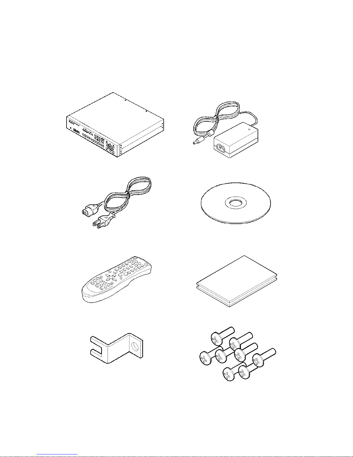
2. Supplied accessories
Unpack and check all the items as below.
1. HVR-04 (1)
2. DC Power Supply (1)
(1 10V~220V)
3. AC Power Cord (1 )
4. CD-ROM (Including DVR manager) (1)
5. Remote Controller (1)
6. Guide (2)
7. Plug Bracket (1)
8. HDD Fixing Screw (8)
8
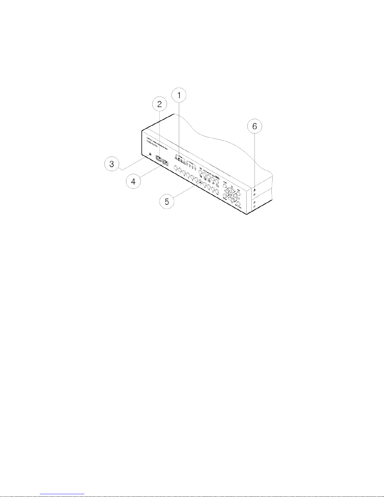
3. Description & Function
HVR-04 front
(1) LED
(2) IEEE1394 connecter
(3) Remote controller receiver
(4) USB connecter
(5) Function buttons
(6) Bracket fixing hole for rack mount
9
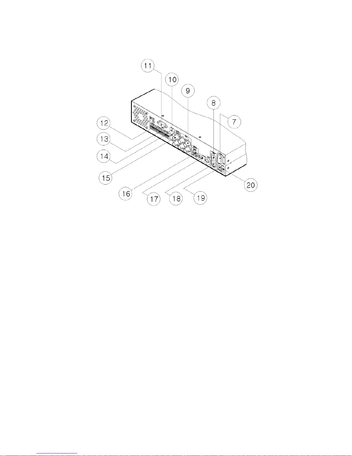
HVR-04 rear
(7) Power switch
(8) Ethernet connector
(9) BNC connector for Video input
(10) Audio input / output connector
(11) RS232 connecter (9Pin D-Sub)
(12) Terminal block for RS232 & 422/485
(13) Terminal block for Sensor input
(14) Terminal block for Relay output
(15) Video output for MONITOR or VCR
(16) Video input type/impedance select & remote controller switch
(17) IEEE1394 connecter
(18) USB connecter
(19) Power connector (DC12V)
(20) GND
10
INSTALLA TION AND CONNECTION
4. Connecting & Running HVR-04
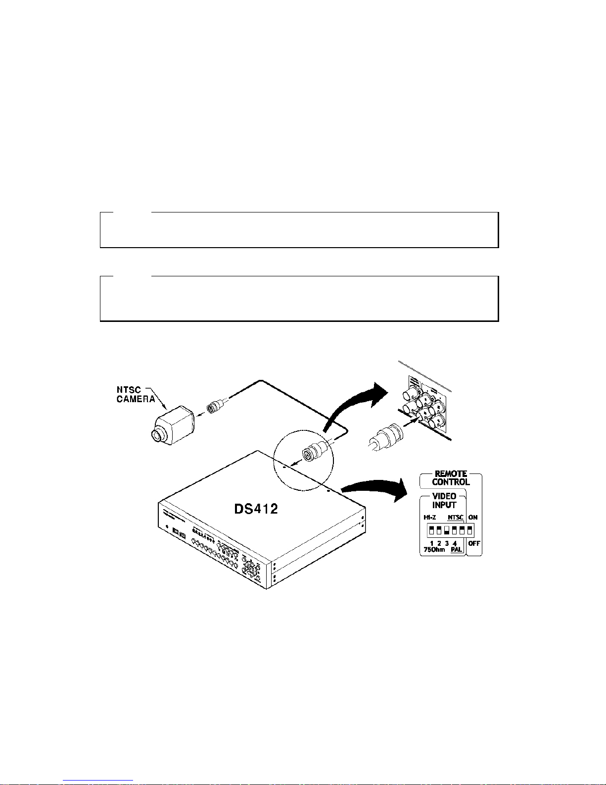
4.1. Connecting camera
(1) Connect CCTV camera to HVR-04 with BNC cable as shown below.
(2) Set video type (NTSC/PAL) by rear panel’s switch.
<Note>
The video type for all channels should be either NTSC or PAL. The only one type must be selected.
(3) Set the impedance control switch for each channel as needed.
<Note>
It may be necessary to configure impedance of video input differently for each channel. For more
detailed information, please refer to “Video type / impedance setup switch” in Appendix #2.
11
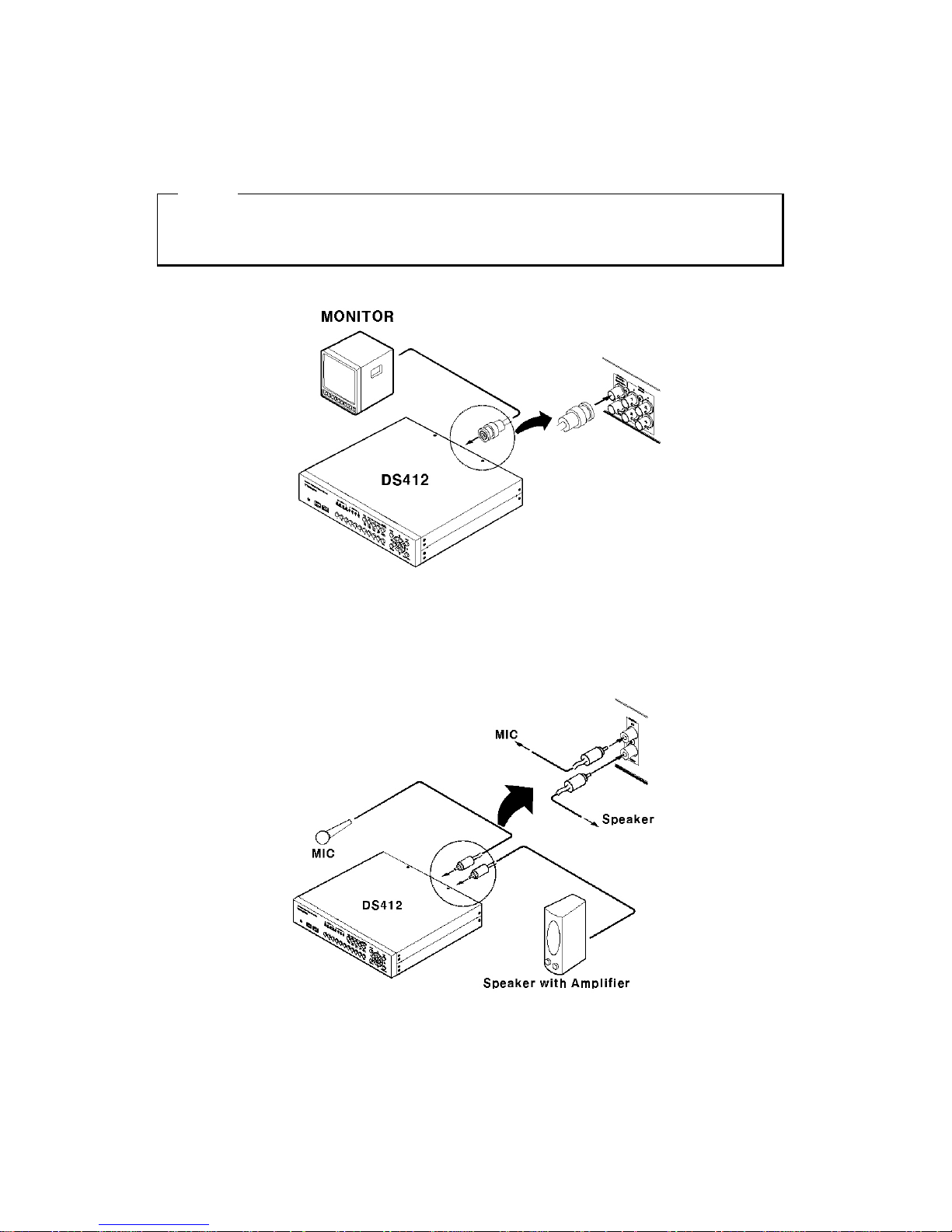
4.2. Connecting monitor
(1) Connect CCTV monitor to HVR-04 with BNC cable as shown below.
<Note>
HVR-04 has two video output ports ; for Monitor and VCR. The output signals from the two ports are
same and either port may be used.
4.3. Connecting audio
(1) Connect audio signal to HVR-04.
12
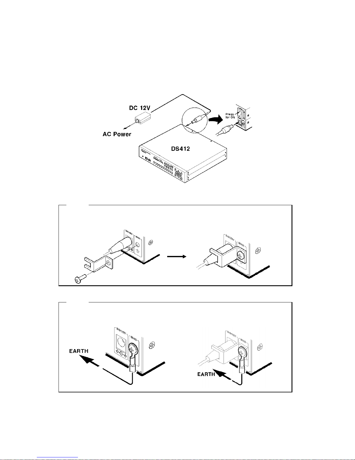
4.4. Supplying power
(1) Connect power cable to HVR-04.
(2) Turn on the power switch located on the HVR-04 rear panel.
<Note>
Use the plug bracket to secure the power cable if needed.
<Note>
To connect EARTH, refer to the following picture.
13
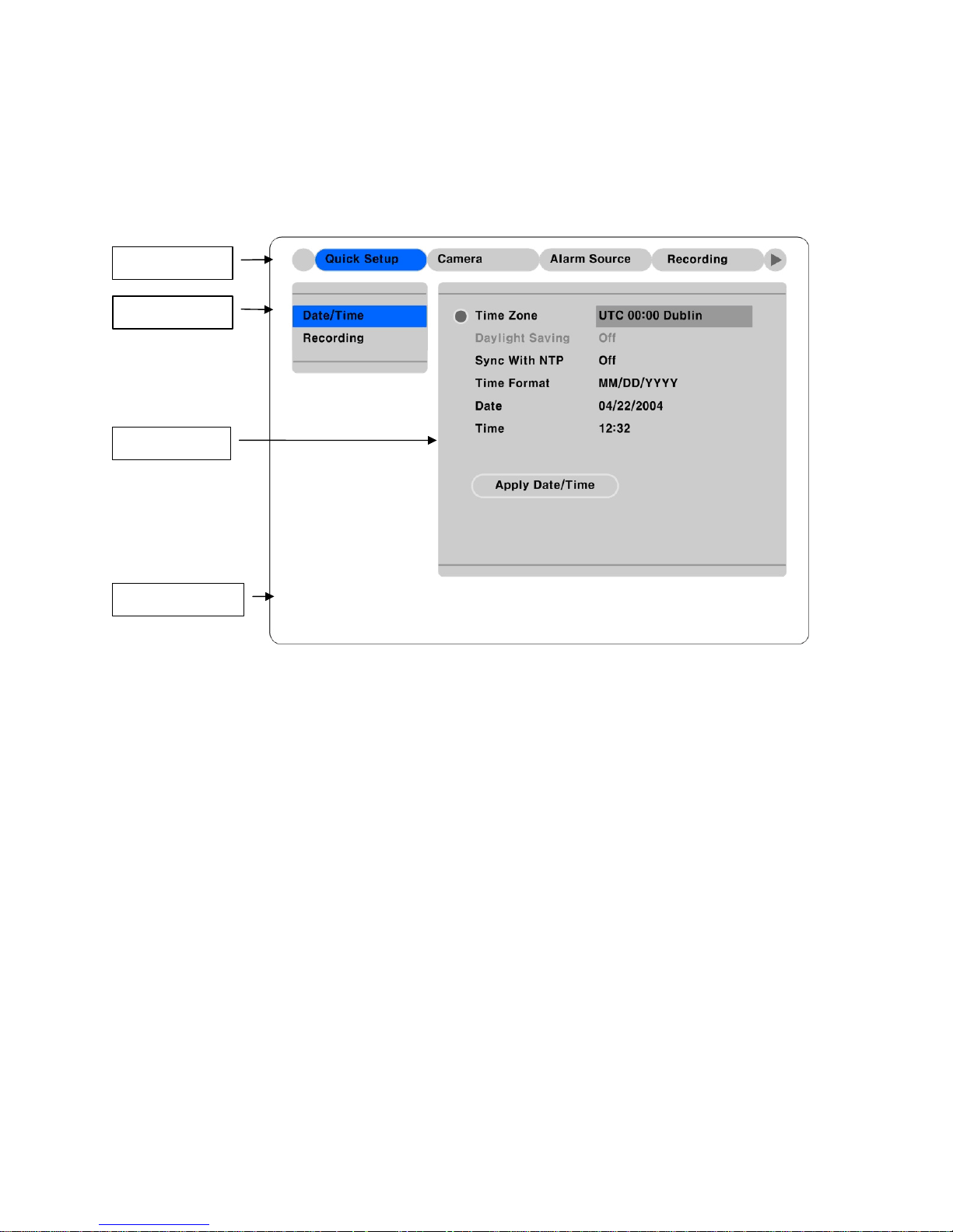
5. Running OSD menu
5.1. Using menu
Press the [MENU] button to open the OSD Configuration Menu.
(1)
Main Menu
(2)
Sub-menu
(3)
Setting Page
(4)
Help message
(1) Main Menu Tabs: The selected tab is shown in blue and the related sub-menus will be shown below
the tab. To move to the previous/next Main Menu Tab, use the [ / ] ◀▶ arrow buttons. To move to a sub-
menu, press the [ENTER] or [▼] buttons.
(2) Sub-menu: The selected sub-menu is shown in blue and the related setting page will be shown to the
right of the sub-menu. Use the [▲/▼] arrow buttons to move within the sub-menu list. To move to the
setting page, press the [ENTER] button. To exit the setting page, press the [EXIT] button.
(3) Setting Page: The selected item is shown in gray. To move within each page, use the [ / ] ◀▶ or
[▲/▼] arrow buttons. Press the [ENTER] button to change the value of a setting. When the setting value
is a word, a dialogue box to edit the word will open. When setting value is a number, it should be set with
using the [ / ] ◀▶ or [▲/▼] arrow buttons. After the value is set, press the [EXIT] button. To exit the
Setting Page, press the [EXIT] button.
(4) Help message: Related information for each menu/setting will be displayed here.
14
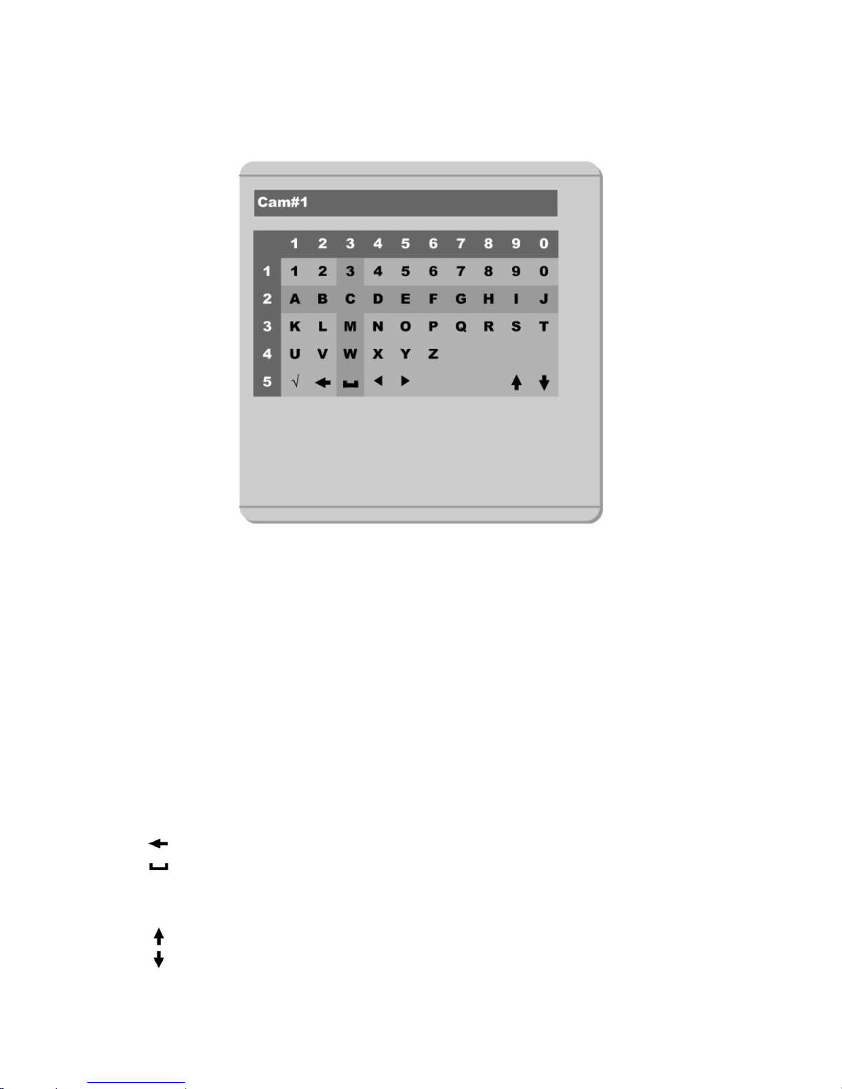
5.2. Dialogue box to edit a word
There are two methods to set word. (The value is displayed as number when number and English is input)
(1) Using number button
Enter the related numbers in order of horizontal/vertical. (For example, in order to select “C”, press [3]
and [2] buttons.)
(2) Using arrow button
Select a value using the [ / ] ◀▶ or [▲/▼] buttons. The intersection of the horizontal and vertical bar is
selected value. Press the [ ]▷ button to confirm the selected value. (The above example is about “C”
input)
(3) Function word
The following symbols are for executing specific functions (The example is about 5 line):
9
: Enter
: Back Space & delete
: Space
◄ : Move to left
► : Move to right
: Previous Code Page
: Next Code Page
15
6. Setting remote controller
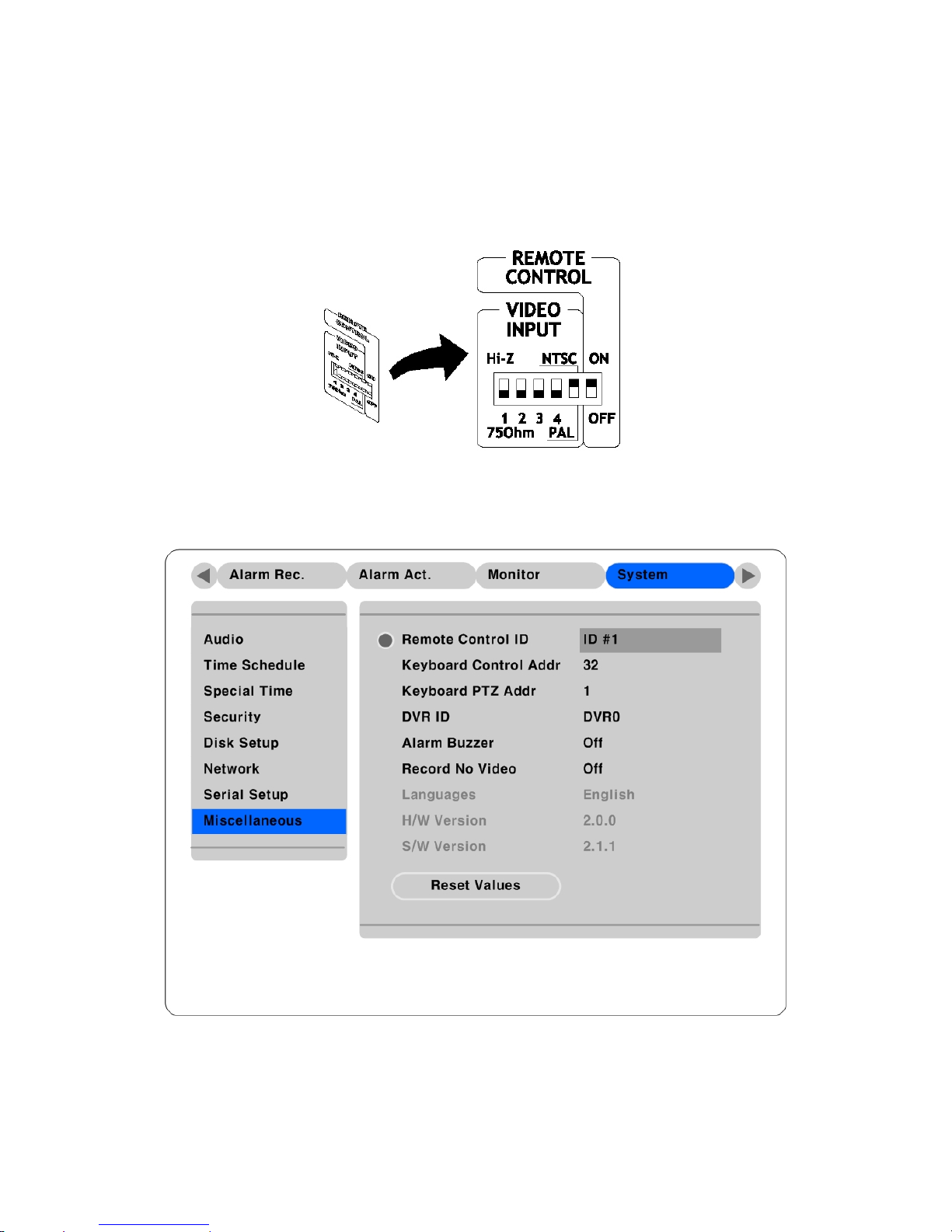
6.1. Setting remote control DIP switch
Set the remote control DIP switch of rear part to “ON.”
6.2. Set ID of HVR-04
When controlling several HVR-04s with one remote controller, set Remote Control ID as follows.
(1) Press [MENU] button.
(2) Select “System” with using [ ] ▶ button and press the [ENETR] or [▼] button.
(3) Select “Miscellaneous” from the sub-menu list using the [▼] button and press the [ENETR] button.
16
(4) Select “Remote Control ID,” and press the [ENETR] button.
(5) Select a value using the [ / ] ◀▶ buttons and press the [EXIT] button.
(6) Press the [EXIT] button to exit the Settings Page and return to Monitor mode.
<Note> Remote Control ID
Up to 16 HVR-04s can be controlled with a single remote controller.
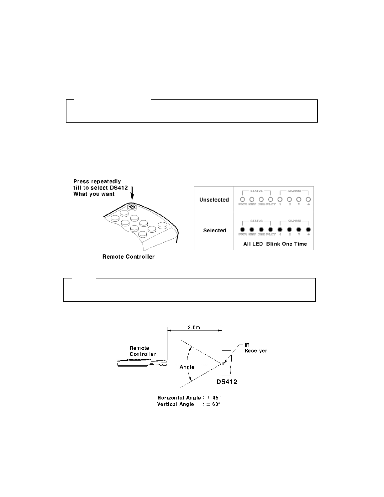
6.3. Selecting HVR-04
If several HVR-04s are set with unique ID numbers, they can be controlled with one remote controller. To
select a specific HVR-04, press the ID button of remote controller repeatedly until the 8 LEDs on the
front of the HVR-04 light up and a buzzer sounds for about 2 seconds.
<Note>
Because remote controller ID is sixteen, HVR-04 will correspond.
6.4. Operable range of remote controller
17
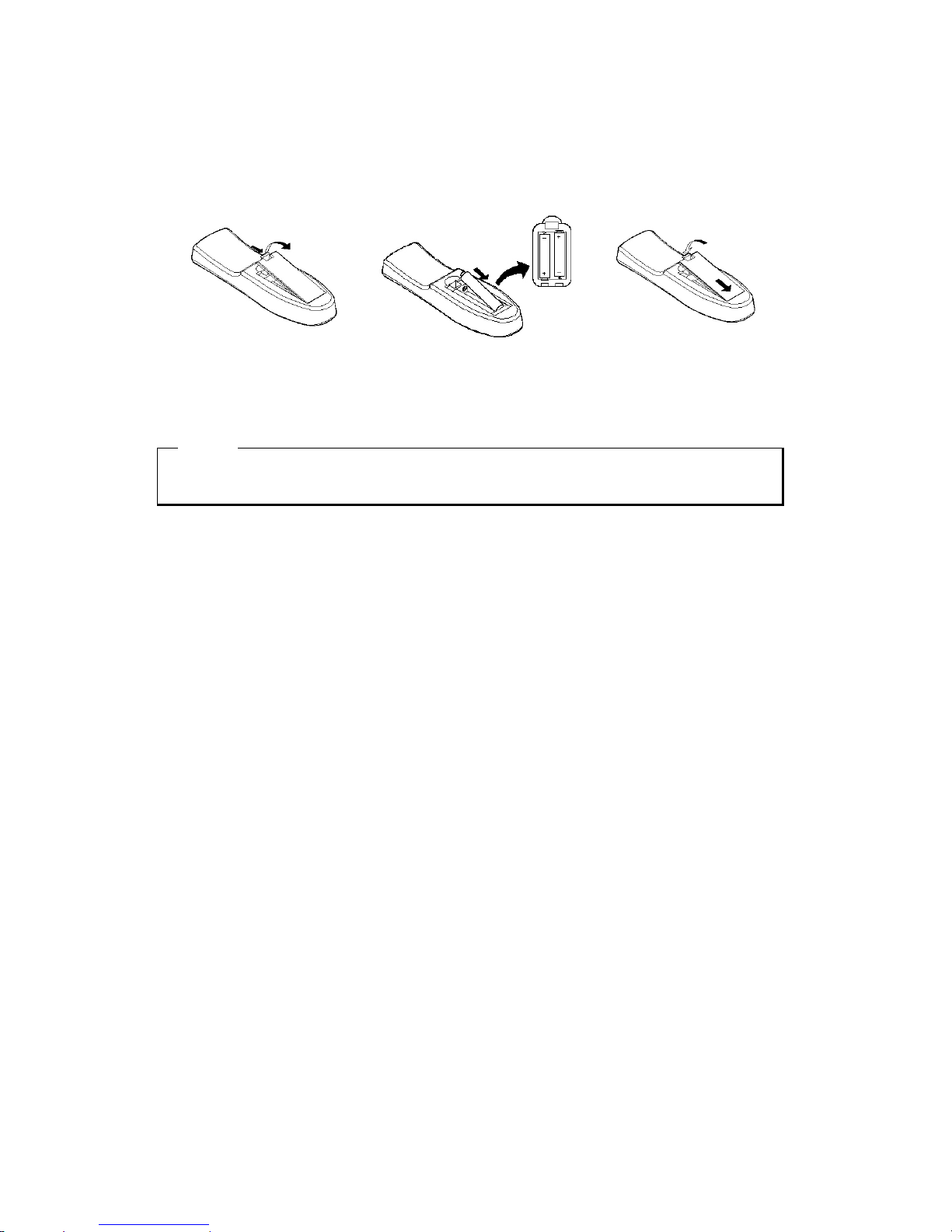
6.5. Loading the batteries into remote controller
Remote controller requires two AAA-type batteries.
1. Remove the battery cover.
2. Taking care that the poles(+/-)
are correctly positioned
3. Replace the battery cover.
<Note>
Batteries are not included as a packing accessory.
18
 Loading...