

Hunt Electronic HTZ-3701WBH Instruction Manual

INSTRUCTION MANUAL Ver 1.2
High Speed Dome Camera
Speed Dome Camera Instruction Manual 2/82
CAUTION
RISK OF ELECTRIC SHOCK
DO NOT OPEN
CAUTION : TO REDUCE THE RISK OF ELECTRICAL SHOCK, DO NOT OPEN THE COVERS.
NO USER SERVICEABLE PARTS INSIDE.
REFER SERVICING TO QUALIFIED SERVICE PERSONAL
This lightning flash with arrowhead symbol is intended to alert the user to
the presence of un-insulated "dangerous voltage" within the product's
enclosure that may be of sufficient magnitude to constitute a risk of electric
shock to persons.
This exclamation point symbol is intended to alert the user to the presence
of important operating and maintenance (servicing) instructions in the
literature accompanying the appliance.
This Device compiles with Part 15 of the FCC Rules. Operation is subject to
the following two conditions:
(1) This device may not cause harmful interface, and
(2) This device must accept any interference received, including
interference that may cause undesired operations.

Speed Dome Camera Instruction Manual 3/82
Important Safety Guide
1. Read, heed and follow all the Instructions
Read all the safety and operating instructions before using the product.
2. Keep this manual
Keep this manual for reference in future.
3. Attachments / Accessories
Use only the attachments or accessories specified by the manufacturer.
4. Installation
z Do not install near any heat resources such as radiators, heat registers, stoves, or other
appratus including amplifiers that product heat. Improperly installed product may fall,
cause serious injury to a child or adult and damage the product.
z Do not block any ventilation holes or openings. Install in accordance with the
manufacturer’s instructions.
z Use only with the cart, stand, tripod, bracket, mounting devices, or table specified by
the manufacturer.
z Installation should be done only by qualified personnel and conform to all the
instructions by the manufacturer.
z Refer all servicing to qualified service personnel.
z Unless the product is specifically marked as IP67, more than IP67 or confirmed by the
manufacturer, it is designed for indoor use only and it must not be installed where
exposed to rain and moisture.
z Do not load on the product.
z Use stainless steel hardware to fasten the mount.
z To prevent damage from water leakage when installing a mount outdoors on a roof or
wall, apply sealant properly around holes.
z These servicing instructions are for use by qualified service personnel only. To reduce
the risk of electric shock, do not perform any servicing other that contained in the
operationg instructions unless you are qualified to do so.
z Use only replacement parts specified by the manufacturer.
5. Power source
This product should be operated only from the type of the power source indicated on the
marking label.
NOTICE

Speed Dome Camera Instruction Manual 4/82
Caution
Operating
z Before using, make sure that the power supply and others are properly installed.
z While operating, if any abnormal condition or malfunction is observed, stop using the
product immediately and then contact your local dealer.
Handling
z Do not disassemble or tamper with the parts inside the product.
z Do not drop or subject the product to shock and vibration as this can damage the
product.
z Care must be taken when you clean the clear dome cover. Especially, scratch and dust
will ruin the quality of the product.
Installation and Storage
z Do not install the product in areas of extreme temperature, which exceed the allowable
range.
z Avoid installing in humid or dusty places.
z Avoid installing in places where radiation is present.
z Avoid installing in places where there are strong magnetic fields and electric signals.
z Avoid installing in places where the product would be subject to strong vibrations.
NOTICE

Speed Dome Camera Instruction Manual 5/82
① Introduction
Model Code
6
Features
7
Packa
g
e Components 10
Main Part Descri
p
tion 12
② Installation
DIP Switch Setu
p
13
Installation with Ceilin
g
Mount Bracket 16
Installation with Wall Mount Bracket
17
Installation with In-Ceilin
g
Mount Bracket 18
W
iring and Cabling 19
③ Operation
Check Point before O
p
eration 22
Check Points for Preset and Pattern Function before O
p
eration 22
OSD Menu
23
Reserved Preset
(
Hot Keys) 23
Preset
24
Swin
g
24
Pattern
25
Grou
p
26
Other Functions
26
OSD Dis
play
28
④ OSD Menu
Quick Pro
g
ramming Guide 29
Main Menu
29
Dis
play
Setup 30
Privac
y
Zone Mask Setup 31
Clock Setu
p
33
Camera Setu
p
34
Motion Setu
p
52
Preset Setu
p
55
Swin
g
Setup 57
Pattern Setu
p
58
Grou
p
Setup 59
Schedule Setu
p
62
Password Setu
p
63
S
y
stem Initialize 65
⑤ Specifications
67
Dimension
82
TABLE OF CONTENTS
Speed Dome Camera Instruction Manual 6/82
Model Code
331T : Optical x33, WDR
370T : Optical x37
371T : Optical x37, WDR
281L : Optical x28, WDR
371L : Optical x37, WDR
280S : Optical x28
281S : Optical x28, WDR

Speed Dome Camera Instruction Manual 7/82
Fe at ure s
Powerful Zoom Camera & Setup Options
z Image Sensor : 1/4" Interline Transfer CCD (
HTZ2701 & HTZ3701 model)
z Zoom :
×27 Optical Zoom, ×16 Digital Zoom (HTZ2701 model)
×37 Optical Zoom, ×16 Digital Zoom (HTZ3701 model)
z Day & Night, Privacy Mask and WDR (
WDR Possible Models Only
)
z DNR (Digital Noise Reduction) Function
z Various Focus Mode : Auto-Focus, Manual Focus, Semi-Auto Focus
z Various Setup Options in OSD Menu.
Powerful Pan/Tilt Functions
z MAX. 500°/sec High Speed Pan/Tilt Motion
z With the Vector Drive Technology, Pan/Tilt motions are accomplished along the
shortest path. As a result, the time to target view is remarkably short and the video on
the monitor is very natural in monitoring.
z With the Micro-Stepping Control Technology, the video looks very natural at high
zoom magnification during a jog operation on a controller since the camera can be
controlled by 0.05°/sec. Hence it is very easy to make the camera focus on desired
target views at high zoom magnification. Additionally it is easy to make the camera
focus on desired positions with zoom-proportional pan/tilt movement.
RTC(Real Time Clock) Function
z Date and Time can be configured for Schedule Function
z With Backup Battery Function, Date and Time configuration should be kept up for a while,
even though power is off
Speed Dome Camera Instruction Manual 8/82
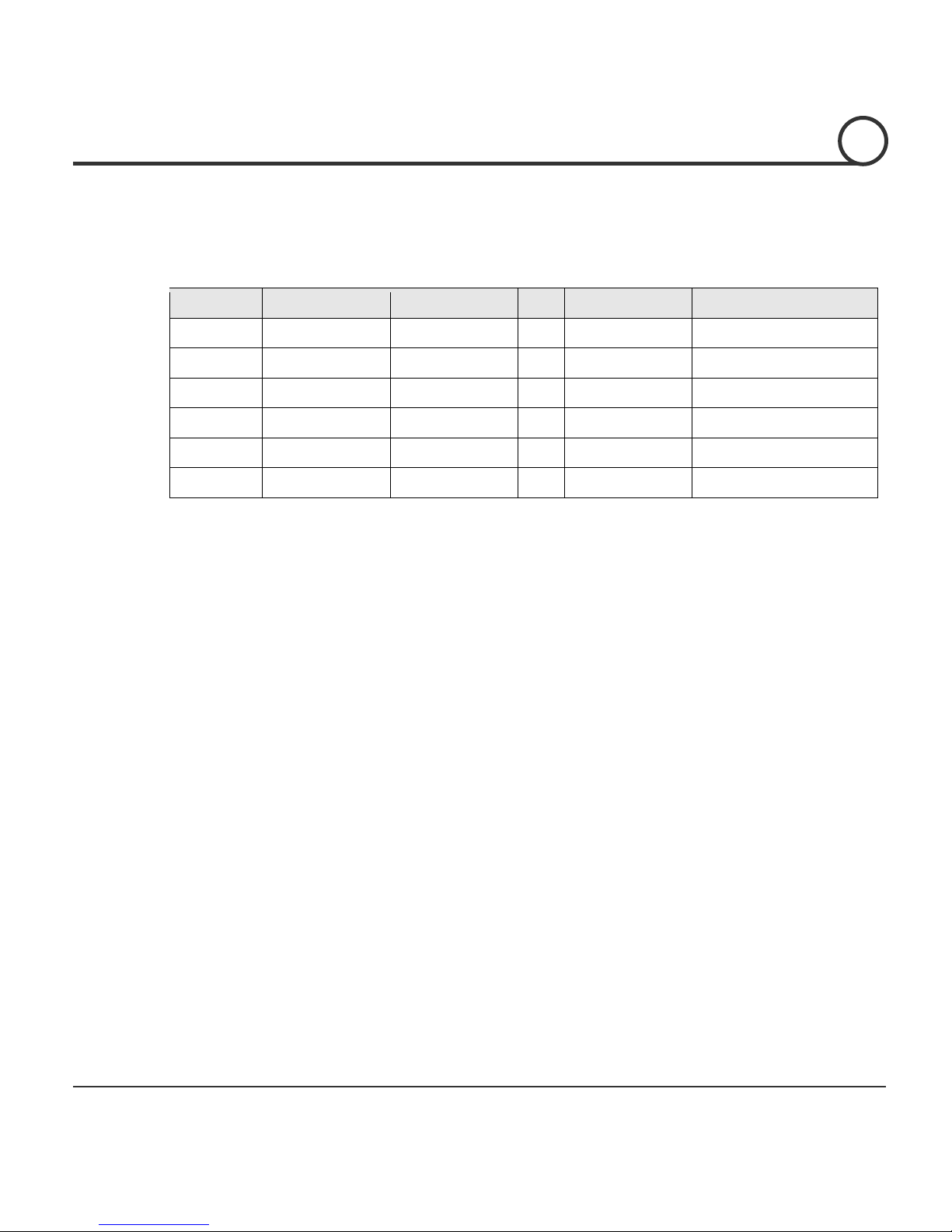
Preset, Pattern, Swing, Group, Schedule, Privacy Mask and More…
z MAX. 209 Presets are programmable and each preset can have its own parameter
values independently from the other presets.
For an example, refer to the below table.
Preset No. White Balanc
e
Auto Exposur
e
••• Label Remark
s
Preset 1 Case A Case 3 “ENTRANCE”
Preset 2 Case C Case 5 “WAREHOUSE”
•••
Preset 95
−−−
−
Reserved for OSDMen
u
•••
Preset 255 Case K Case 9 “TERRACE”
z MAX. 10 sets of Swing are programmable. This function is that a camera moves
repetitively between two preset positions at programmed speeds.
z MAX. 8 Patterns are programmable. This function is that a camera memorizes the path
(mostly curve path) by the joystick of the controller and revives the trajectory
operated by the joystick as closely as possible.
z MAX. 8 sets of Group are programmable. This function is that a camera memorizes the
combination of Presets, Pattern and/or Swings sequently and runs Presets, Pattern
and/or Swings repetitively. A Group can be combined upto 40 functions with any of
Preset/Pattern/Swing.
z MAX. 8 Privacy Masks are programmable, not to intrude on any other’s privacy.
z
MAX. 8 sets of Schedule are programmable. This function is that a camera runs a function
such as Preset, Pattern, Swing or Group at an assigned time. Also this function can be run
periodically by pre-defined schedules.
PTZ(Pan/Tilt/Zoom) Control
z With the RS-485 communication connection, MAX. 255 units of cameras can be
connected to a single controller.
z Pelco-D or Pelco-P protocols can be selected as a control protocol in the current
firmware version.
OSD(On Screen Display) Menu
z OSD menu is provided to display the status of camera and to configure the functions
interactively. A P
assword can be configured in OSD menu and OSD menu can be protected.
z The information such as Camera ID, Pan/Tilt Angle, Time/Date, Direction, Alarm Input
and Preset is displayed on screen.
z
Multi-Language OSD menu is supported.
INTRODUCTION
1

Speed Dome Camera Instruction Manual 9/82
Alarm In/Out Function
z 3 alarm sensor inputs and 1 alarm sensor outputs are available.
z Alarm sensor input is decoupled with photo-couplers to avoid external electric noise
and shock perfectly.
z Both of N.O.(Normal Open) sensors and N.C.(Normal Close) sensors can be used and
the signal range of the sensor input is from DC 5.0V to 12.0V for various applications.
z The camera can be set to move to a Preset position or to run functions such as Pattern,
Swing and Group when there are external sensor activations. Also “Post Alarm”
function is possible, which is supposed to activate after user-defined time period and
sequentially in succession to the action by external sensor activations.
Reserved Presets(Hot Keys)
z Most camera setup options can be set up easily and directly with the reserved presets
(Hot Keys), without entering into OSD menu. For more information, refer to “Reserved
Presets(Hot Keys)” in this manual.
Dual Power Input
z The input power source is DC 12 V or AC 24 V.
Perfect Outdoor Environment Compatibility and Easy Installation
z The fans and heaters are built-in in the camera for cold and hot temperature
environment. Also idealistic mechanical design protects the camera from water and
dust. (IP67 when installed properly with wall mount bracket only / Only for outdoor
models)
z It is easy to install and repair the camera.
INTRODUCTION
1

Speed Dome Camera Instruction Manual 10/82
Package Component
Product & Accessories
z Main Body & Dome Cover (Wa l l / C e i l i ng model
)
z Main Body & Dome Cover (In-ceiling model
)
Manual
z Default Accessorie
s
[
Main Cable, I/O Cable ,Wrench, Owner’s Manual
]
INTRODUCTION
1
Speed Dome Camera Instruction Manual 11/82
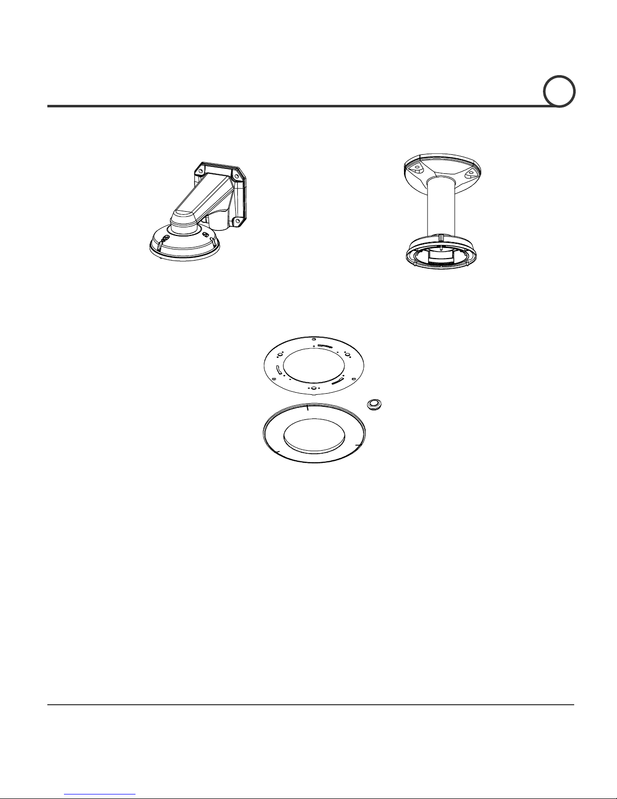
Brackets (Optional)
z Wa l l M o u n t B r a ck e
t
[Screws : TORX Machine M4×L18, H e x Lag
#14×50]
z Ceiling Mount Bracke
t
[Screws : TORX Machine M4×L18, A n chor Bol t
3/8"×70]
z In-Ceiling MountBracket
[Screws : Tapping FH Ø4×L20, Machine Sams M3×L8]
INTRODUCTION
1
Speed Dome Camera Instruction Manual 12/82
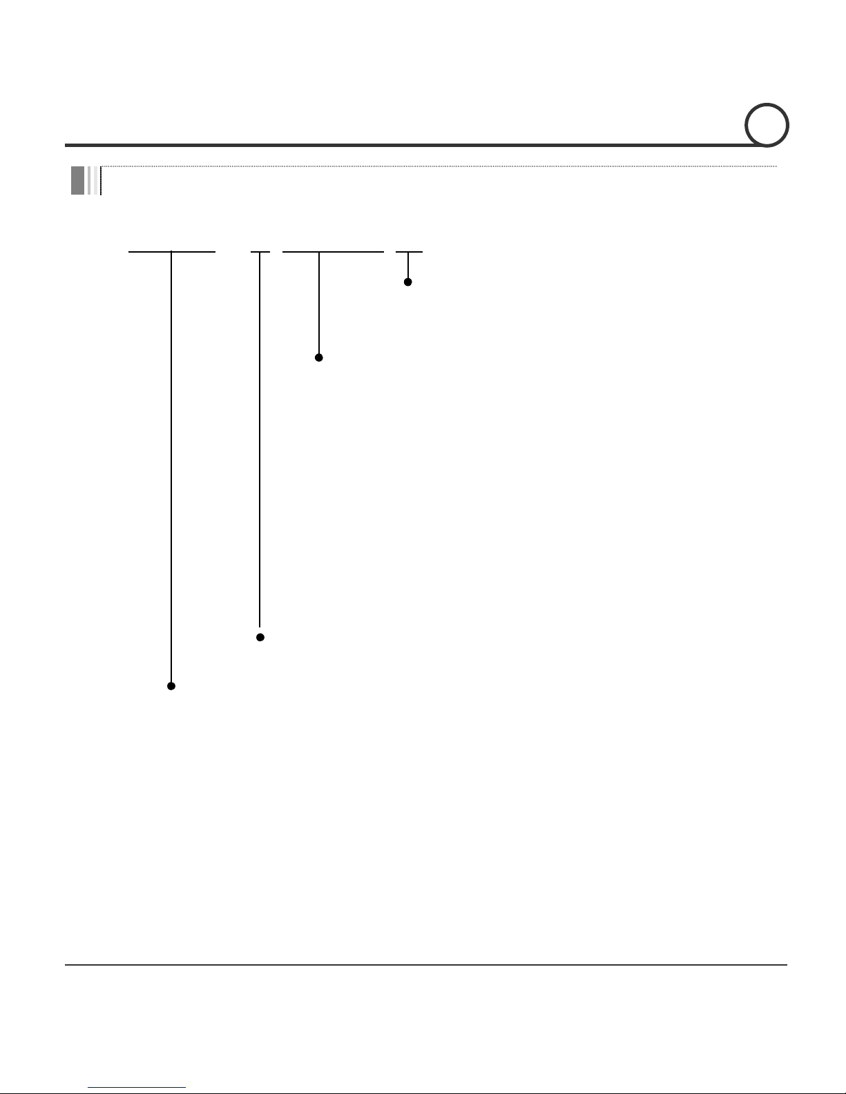
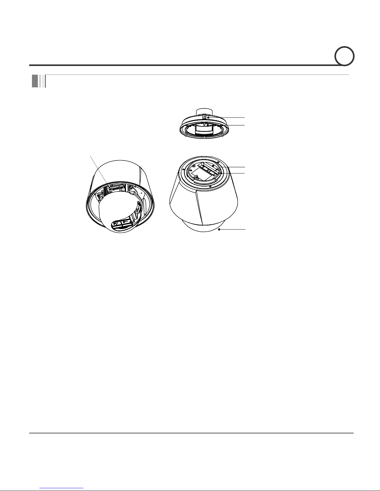
Main Part Description
DIP Switch
Main Connector
Sensor I/O Port
Dome Cover
Mounting Screw Hole
Drop Prevention Spring
z Dome Cover Do not detach the protection vinyl from the dome cover before
finishing all the installation process to protect the dome cover from
scratches or dust.
z DIP Switch Used to set u
p
camera IDs and protocols.
z Drop Prevention
Spring
This part keeps the camera from dropping during installation and
maintenance. After install the Bracket, please, hang the spring to
the drop prevention hook of main body as shown in picture for
further tasks.
z Mounting Screw Hole Used to assemble the main body with a bracket with screws.
z Main Connector Used for the power wi re, the video cable and th e R S -485
communication cable connection.
z Sensor I/O Por
t
Used for the sensor in/out connection.
INTRODUCTION
1
Speed Dome Camera Instruction Manual 13/82
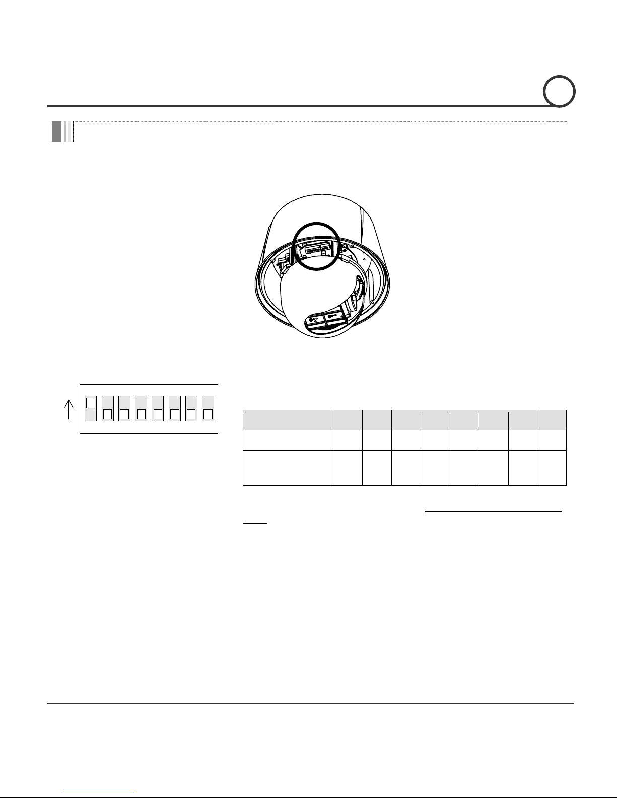
DIP Switch Setup
Before installing the camera, set up the DIP switch to configure the camera ID and the
communication protocol.
Camera ID Setup
ON
ON
12345678
z ID numbers of cameras are set up with binary numbers.
See the examples shown below.
Pin 1 2 3 4 5 6 7 8
Binary Value 1 2 4 8 16 32 64 128
ex) ID=5 on off on offoffoffoffof
f
ex) ID=10 offon offon offoffoffof
f
z The camera ID range is “1~255”. Camera ID must not be
“0”!
z The factory default of the camera ID is “1”.
z Match the camera ID with the Cam ID setting of your DVR
or Controller to control the camera.
z If you are connecting a single camera to a controller,
terminate the camera. When connecting more than one
camera to a single controller, terminate the last camera on
the communication line. The last camera means the camera
farthest in cable length from the controller.
z Note that the total length of the communication cable
between a controller and the camera(s) on the same
communication line must be less than 1.2Km.
INSTALLATION
2
Speed Dome Camera Instruction Manual 14/82
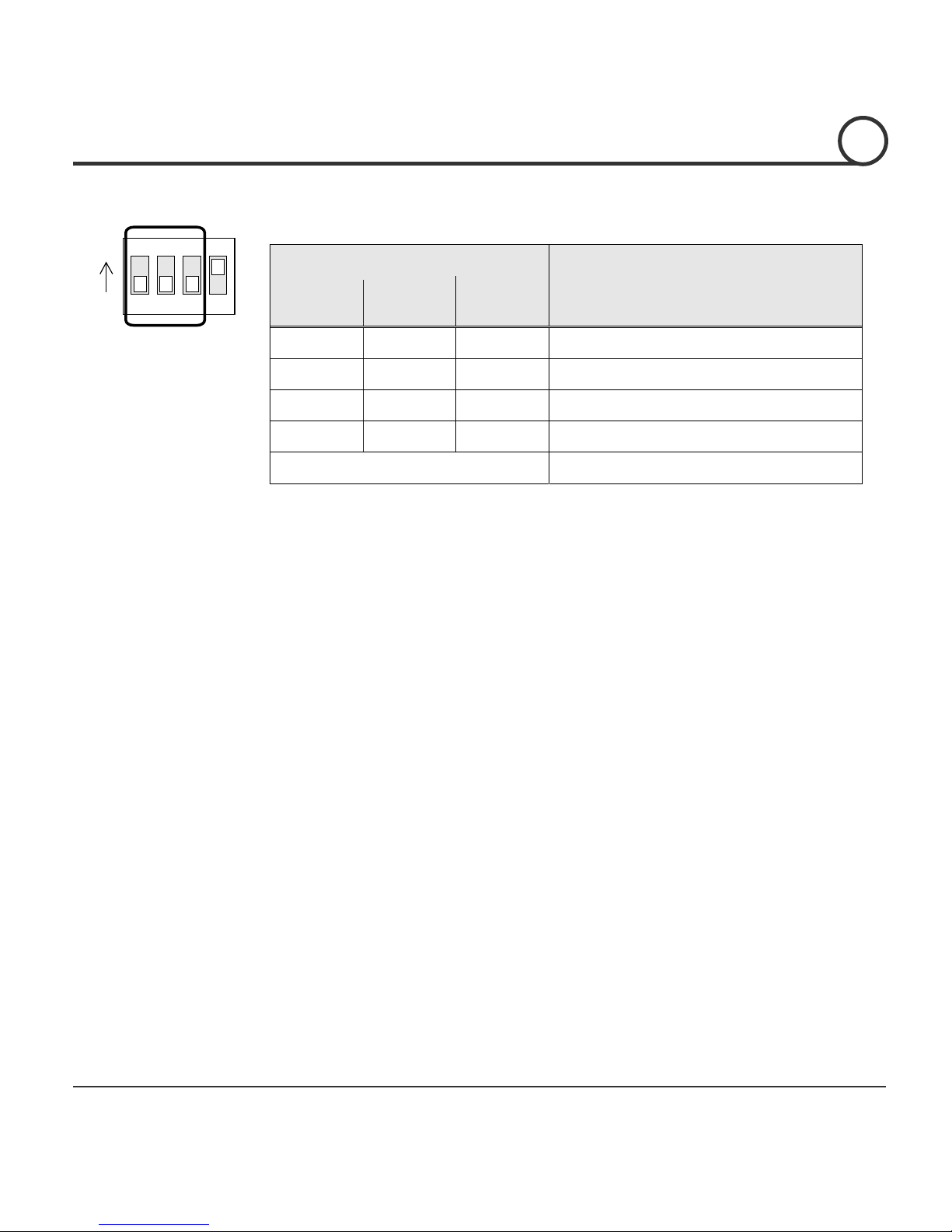
Communication Protocol Setup
1234
ON
ON
z Select an appropriate Protocol with the DIP switch combination.
Switch Mode
Protocol
P0
(Pin 1)
P1
(Pin 2)
P2
(Pin 3)
OFF OFF OFF PELCO-D, 2400 bps
ON OFF OFF PELCO-D, 9600 bps
OFF ON OFF PELCO-P, 4800 bps
ON ON OFF PELCO-P, 9600 bps
Others Reserved
z Match the camera protocol with the camera protocol in the setting of
your DVR or controller to control the camera.
z Adjust the DIP switch after turning off the camera. If you changed the
camera protocol by changing the DIP S/W, the change will be effective
after you reboot the camera.
z The factory default protocol is “Pelco-D, 2400 bps”.
INSTALLATION
2
Speed Dome Camera Instruction Manual 15/82
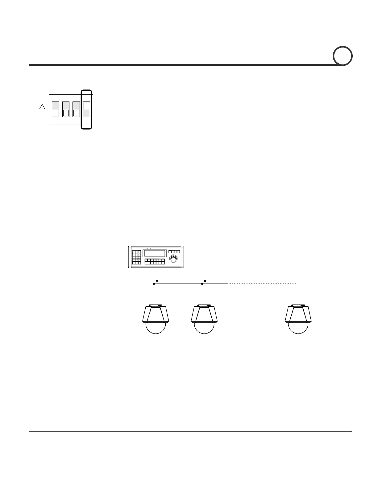
Terminal Resistor Setup
1234
ON
ON
T
he terminal resistor is used for the following cases.
z Case 1 : In case that the control cable length between a camera and
a controller is relatively very long (1:1 Connection)
If the communication cable length is very long, the electrical signal will
bound in the terminal point. This reflected signal causes distortion of
original signal. Accordingly, the camera can be out of control. In this
case, the terminal resistor of both sides i.e. the camera and the
controller must be set to ‘ON’ state.
z Case 2 : In case that multiple cameras are connected to a
controller.
Due to similar reasons with the case 1, the terminal resister of the
controller and the last camera must be set to ‘ON’ state. The last camera
means the camera farthest in cable length from the controller. Do not
turn on the terminal resistor of all the cameras on the same
communication cable.
Controller
#1 #2 #n
Terminal Resistor ON
RS-485
Terminal Resistor
OFF
Terminal Resistor
OFF
Terminal Resistor
ON
INSTALLATION
2
Speed Dome Camera Instruction Manual 16/82
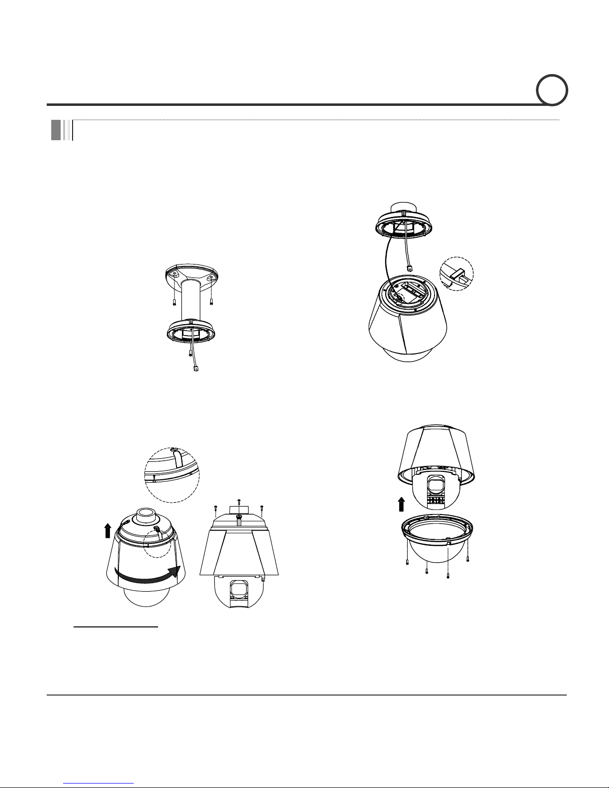
Installation with Ceiling Mount Bracket
①
Remove the ceiling tile from the ceiling
and cut a hole whose diameter is
30~40mm on the ceiling tile to pass the
wire(s) and cable(s) through to the upside
of the ceiling. (In case of the wiring and
cabling through the mounting surface
only) Then prepare the ceiling mount
bracket. Pull the wire(s) for the system as
below. (Anchor Bolt 3/8"×70)
②
Hook up “Drop Prevention Spring”on
main body to prevent camera from
unexpected drop and pull the wire(s) and
cable(s) for the system as below.
Spring Wire Hook
③
Line up the mold lines and assemble
main body to mount adaptor and turn it.
And assemble the main both with the
camera mount adaptor with the 3 screws.
(
TORX SCREW M4×18).
END
START
④
Screw the dome cover to the main body
and remove the protection vinyl from the
dome cover.
Important Notice
z Before starting the installation, make sure that the Camera ID and Protocol are set up properly.
z To adjust the installation height from the mounting surface, the pipe and coupler should be needed
between the surface mount part of the ceiling mount bracket and the camera mount part of the ceiling
mount bracket. Note that they are not supplied by the manufacturer.
INSTALLATION
2
Speed Dome Camera Instruction Manual 17/82
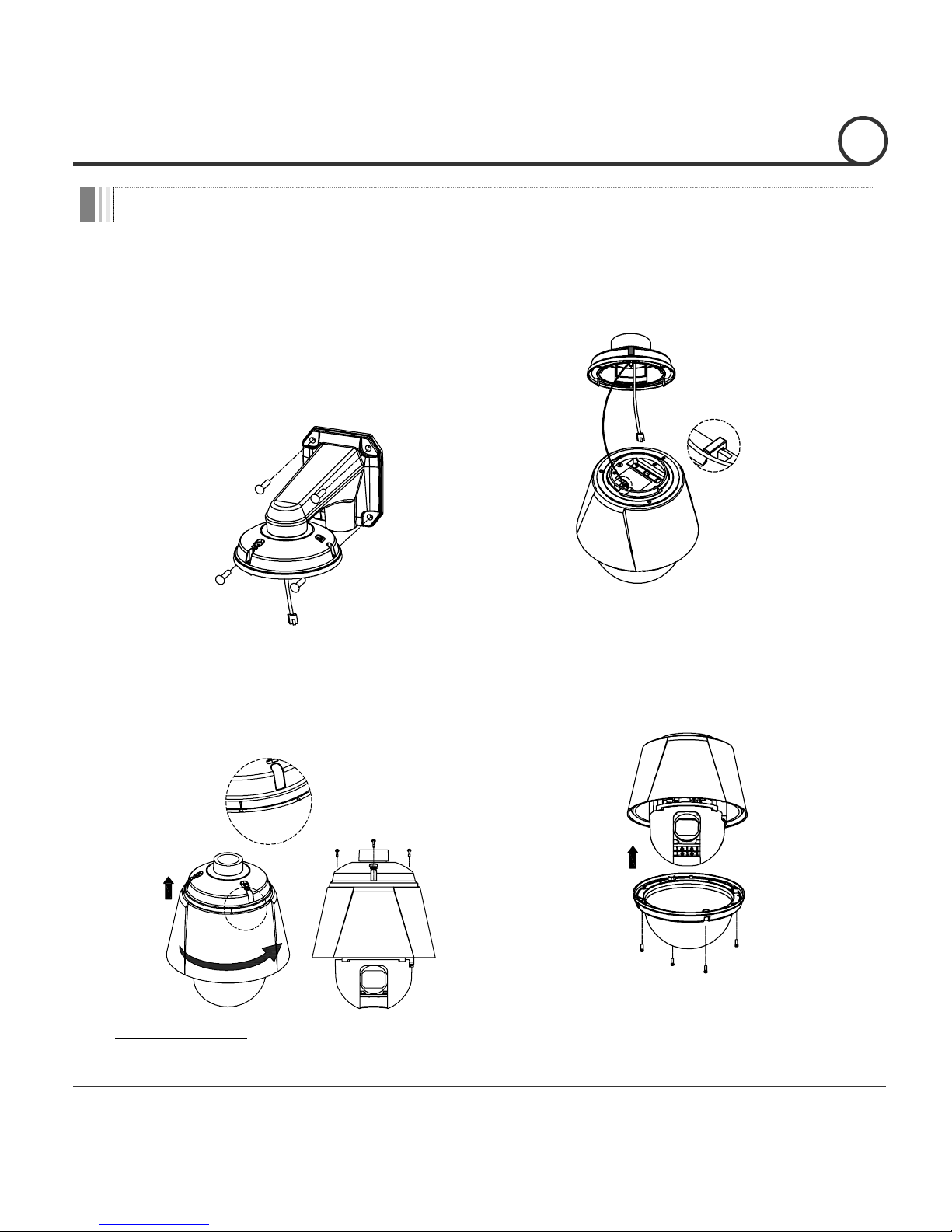
Installation with Wall Mount Bracket
①
Make a hole whose diameter is 30~40mm
on the mounting surface to pass the
wire(s) and cable(s) through the mounting
surface. (In case of the wiring and cabling
through the mounting surface only) Then
prepare the wall mount bracket. Pull the
wire(s) and cable(s) for the system as
below. Attach the wall mount bracket to
the mounting surface. (Hex Lag #14×50)
②
Hook up “Drop Prevention Spring”on
main body to prevent camera from
unexpected drop and pull the wire(s) and
cable(s) for the system as below.
Spring Wire Hook
③
Line up the mold lines and assemble
main body to mount adaptor and turn it.
And assemble the main both with the
camera mount adaptor with the 3 screws.
(
TORX SCREW M4×18).
END
START
④
Screw the dome cover to the main body
and remove the protection vinyl from the
dome cover.
Important Notice
z Before starting the installation, make sure that the Camera ID and Protocol are set up properly.
INSTALLATION
2
Speed Dome Camera Instruction Manual 18/82
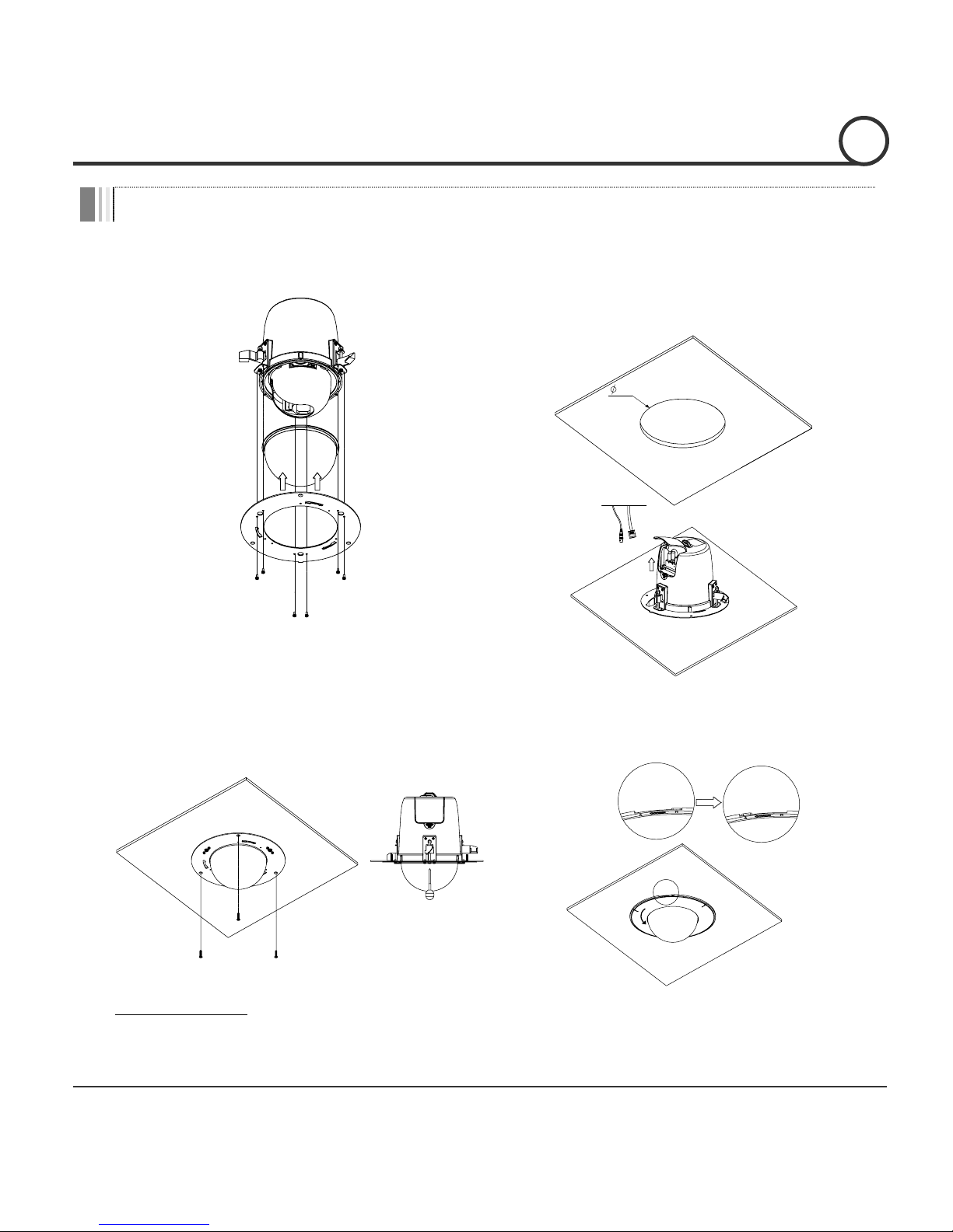
Installation with In-ceiling Bracket
①
Assemble the dome cover and the braket
with the main body
② Cut a hole whose diameter is 215mm on
the ceiling tile and insert the camera into
the hole. Open the cover and make all the
connections.
215
③
Install the ceiling tile to the ceiling. Fix
the camera to the ceiling tile with the
Guide Hook Screws.
④
Assemble the Deco-Ring with the camera by
spinning.
Important Notice
z Before starting the installation, make sure that the Camera ID and Protocol are set up properly.
INSTALLATION
2
Speed Dome Camera Instruction Manual 19/82
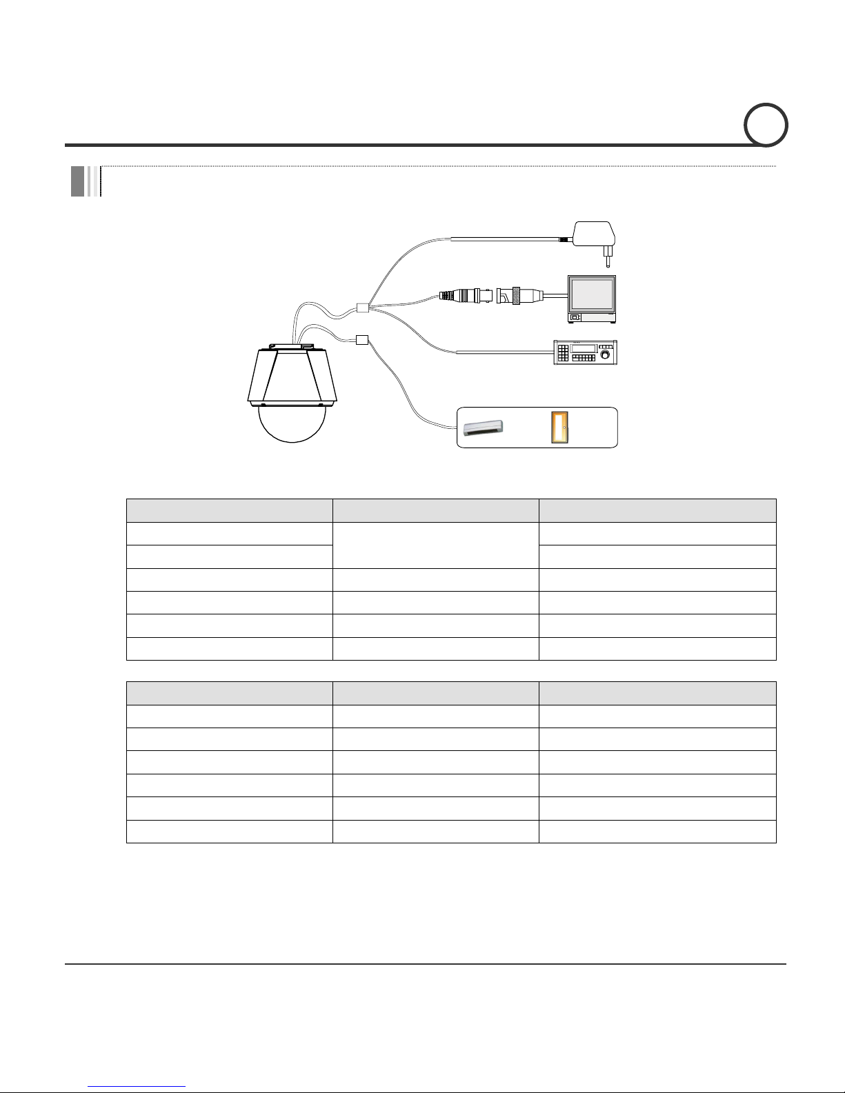
W
iring and Cabling
RS-485
BNC
SENSOR I/O
MAIN CABLE
I/O CABLE
POWER
MONITOR
CONTROLLER / DVR
IR
SENSOR
DOOR
SWITCH
Port Description
z Main Cable
Port Pin Number (RJ45) Connector / Wire Color Signal
1
BNC Connector
V
ideo +
2,4
V
ideo −
5 Red RS-485 +
3
Y
ellow RS-485 −
7 Orange Power +
6,8
W
hite Power −
z I/O Cable
Port Pin Number (RJ25)
W
ire Color Signal
1 Blue IN COM +
2
Y
ellow IN 1 −
3 Green IN 2 −
4 Red IN 3 −
5 Black OUT A
6
W
hite OUT B
INSTALLATION
2
Speed Dome Camera Instruction Manual 20/82
Power Description
z Carefully check the voltage and current capacity of the rated power.
Model Input Voltage Range
Current
Consumption
DC12V Input
Without F/
HECI
Serie
s
DC 11V ~ 18V
1.0 A
With F/
H
ECO Serie
s
1.8 A
AC24V Input
Without F/
H
ECISerie
s
AC 17V ~ 29V
0.8 A
With F/
H
ECO Serie
s
1.8 A
z For the DC input, be careful with the polarity of DC power. The system should be
permanentally damaged by wrong DC input.
z In case that the length of the power wire is very long, there may be voltage drop and the
syatem may not work properly. Make the length of the power wire as short as possible.
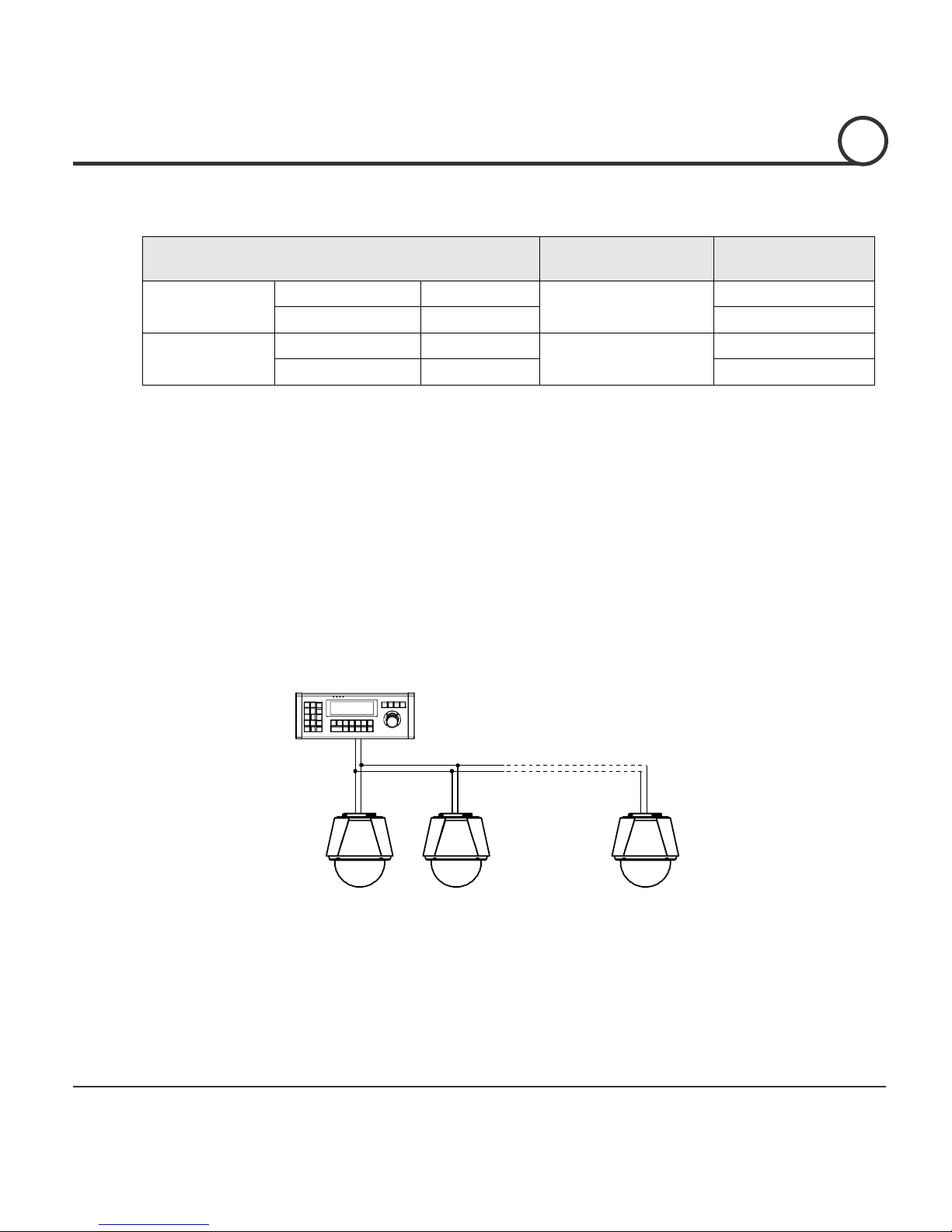
RS-485 Communication
z For PTZ control, connect the cable(s) to your keyboard or DVR. To connect multiple
cameras to a single controller, RS-485 communication should be connected in parallel as
shown below. If you are connecting a single camera to a controller, terminate the camera.
When connecting more than one camera to a single controller, terminate the last camera
on the communication line. The last camera means the camera farthest in cable length
from the controller. Note that the total length of the communication cable between a
controller and the camera(s) on the same communication line must be less than 1.2Km.
INSTALLATION
2
CONTROLLER / DVR
RS-485
+
-
#1
+
-
#2
+
-
#n
+
-
Speed Dome Camera Instruction Manual 21/82
Video
z Use BNC coaxial cable only.
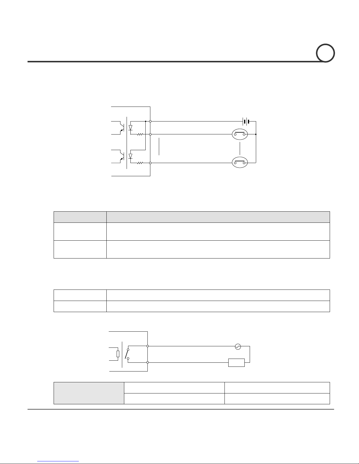
Alarm Input
Before connecting sensors, check driving voltages and output signal types of the sensors.
Since output signal types of the sensors are divided into Open Collector type and
Voltage Output type in general, the wiring must be done properly after considering
those types.
Signal Description
IN COM+ The electric power source to drive input circuit. Connect the (+) wire of electric
power source to drive the Sensors to this port as shown in the above circuit.
IN1 -, IN2 -, IN3 - Connect the outputs of sensors to each port as shown in the above
circuit.
If you want to use Alarm Input, the types of sensors must be selected in OSD menu. The
sensor types are divided into Normal Open and Normal Close. If wrong sensor types are
selected, alarms should be activated reversely to sensor inputs.
~ Normal Open Output Voltage is high state when sensor is activated
~ Normal Close Output Voltage is high state when sensor is not activated
Relay Output
Internal
OUT 1
AC or DC
LOAD
The maximum loads are as follows.
Power Type DC Power AC Power
Maximum Load MAX. DC 24V, 1A MAX. AC 125V, 0.5A
IN COM+
+5V~12V
IN 1-
IN 3-
+
+
-
-
+
-
Internal
Sensor 1
Sensor 3
INSTALLATION
2
Speed Dome Camera Instruction Manual 22/82
Check Points before Operation
z Before turning on the system, check if the wire(s) and cable(s) are connected properly.
z Check if the camera ID on the controller is properly selected. The camera ID must be
identical to that of the target camera. The camera ID can be checked by reading the DIP
switch of the camera or on OSD.
z If your controller supports multi-protocols, the protocol must be changed to match to that of
the camera.
z Adjust the DIP switch after turning off the camera. If you changed the camera protocol by
changing the DIP S/W, the change will be effective after you reboot the camera.
z Since the operation method can be different by controllers, refer to your controller manual
if the camera can not be controlled properly. The operation of this manual is based on the
standard Pelco® Controller.
Check Points for Preset and Pattern Function before Operation
z Check fully how to operate preset function and pattern function with your controller or DVR
in advance to operate the camera functions when using a controller or a DVR.
z Refer to the following table when using standard Pelco® protocol controllers.
< Go Preset > Input [Preset Number] and press [Preset] button shortly.
< Set Preset > Input [Preset Number] and keep pressing [Preset] button for more than 2 seconds.
< Run Pattern > Input [Pattern Number] and press [Pattern] button shortly.
< Set Patter n > Input [Pattern Number] and keep pressing [Pattern] button for more than 2 seconds.
z If your controller or DVR has no pattern button or function, use the Hot Keys with preset
numbers. For more information, refer to “Reserved Presets(Hot Keys)” in this manual.
OPERATION
3
Speed Dome Camera Instruction Manual 23/82
OSD Menu
z Function
W
ith OSD menu, the system can be properly configured for each
application.
z Entering into OSD Go Preset [95]
Reserved Presets (Hot Keys)
z Description Some Preset numbers are reserved to change some parameter
s
w
ithout entering into
OSD menu.
z Hot Key
s
Go Preset [95] : Entering into OSDmenu
Go Preset [131~13
8
] : Running Pattern Function 1 ~ 8
Go Prese
t
[141~150] : Running Swing Function 1 ~ 10
Go Preset [151~158] : Running Group Function 1 ~
8
Go Preset [161] : Turning off Relay Output
Set Preset [161] : Turning on Relay Outpu
t
Go Preset [167] : Setting Zoom Proportional Function to O
N
Set Preset [167] : Setting Zoom Proportional Function to OFF
Go Pre
s
et [170] : Setting Camera BLC/WDR Mode to OFF
Go Preset [171] : Setting Camera BLC/WD
R
Mode to O
N
Go Preset [174] : Setting Camera Focus Mode to AUTO
Go Preset [175] : Setting Camera Focus Mode to Manual
Go Preset [176] : Setting Camera Focus Mode to SEM
I
-
AUTO
Go Preset [177] : Setting Day & Night Mode to AUTO
Go Preset [178] : Setting Day & Night Mode to NIGHT
Go Preset [179] : Setting Day & Night Mode to DAY
Go Preset [190] : Setting OSD Display Mode to AUTO (Except Privacy Mask)
Go Pre
s
et [191] : Setting OSD Display Mode to OFF (Except Privacy Mask)
Go Preset [192] : Setting OSD Display Mode to ON (Except Privacy Mask)
Go Preset [193] : Setting all Privacy Mask Display to OFF
Go Preset [194] : Setting all Privacy Mask Display to O
N
OPERATION
3
Speed Dome Camera Instruction Manual 24/82
Preset
z Function MAX. 209 presets can be confi
g
ured except the Reserved Presets (Hot
Keys).
Camera parameters such as White Balance, Auto Exposure and
others can be set up independently and each preset can have its own
parameter values independently from the other persets. When
setting up presets with a controller, Label should be blank and
"Camera Adjust" should be set to "GLOBAL" as the default. To
change the parameters, enter into OSD menu.
z Setting Presets Set Preset [1~255]
z Running Presets Go Preset [1~255]
z Deleting Presets To delete Presets, enter into OSD menu.
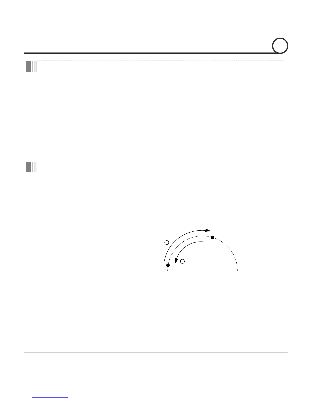
Swing
z Function This function is that the camera moves repetitively between two
preset positions at programmed speeds. When a swing function runs,
the camera moves from the preset assigned as the 1st point to the
preset assigned as the 2nd point in CW(Clockwise) direction. Then
the camera moves from the preset assigned as the 2nd point to the
preset assigned as the 1st point in CCW(Counterclockwise)
direction.
In case that the preset assigned as the 1st point and the preset
assigned as the 2nd point are same, the camera turns on its axis by
360° in CW(Clockwise) direction and then it turns back on its axis by
360° in CCW(Counterclockwise) direction. The Swing speed is
defined from 1°/sec to 180°/sec.
z Setting Swings To set Swin
g
, enter into OSD menu.
z Running Swings
Method 1) <Run Pattern> [Swing NO. + 10]
Method 2) <Go Preset> [Swing NO. + 140]
ex) Run Swing 3 : <Run Pattern> [13]
ex) Run Swing 3 : <Go Preset> [143]
z Deleting Swings To delete Swings, enter into OSD menu.
1st Preset
2nd Preset
1
C
W
D
ir
e
ct
io
n
2
CCW
D
ir
e
ct
io
n
OPERATION
3
Speed Dome Camera Instruction Manual 25/82
Pattern
z Function This function is that the camera memorizes the path (mostly curve
path) by the joystick of the controller and revives the trajectory
operated by joystick as closely as possible.
MAX. 8 Patterns are programmable and Maximum 880
communication commands can be programmed in a pattern.
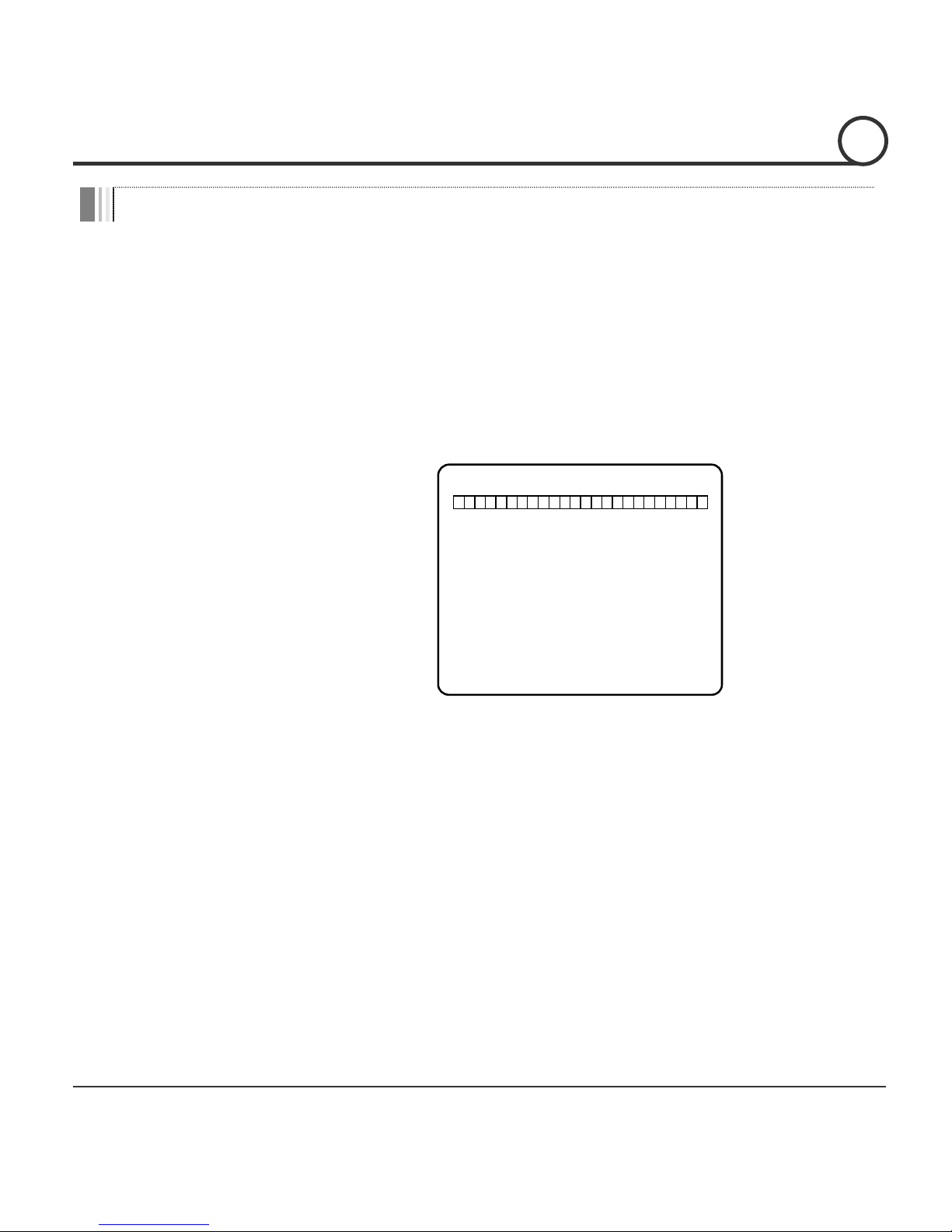
z Setting Patterns A Pattern can be created by the following methods.
Method 1) <Set Pattern> [Pattern NO.]
{ The Pattern programming window appears on the monitor as
below.
EDIT PATTERN 1
[NEAR:SAVE /FAR:DELETE]
0/0/x1/N
{ The movement by Joystick and the preset movement can be
memorized in a pattern.
{ After a pattern is programmed, the remaining storage is
displayed in progress bar on the screen.
{ To save the recording, press NEAR key and to cancel, press
FAR key.
Method 2) Programming in OSD Menu : See the section “How to use OSD Menu”.
z Running Patterns
Method 1) <Run Pattern> [Pattern NO.]
Method 2) <Go Preset> [Pattern NO. + 130]
ex) Run Pattern 2 : <Run Pattern> [2]
ex) Run Pattern 2 : <Go Preset> [132]
z Deleting Patterns To delete Patterns, enter into OSD menu.
Note) When the system memorizes Patterns, the commands are stored in the momories, not
the positions of Pan/Tilt/Zoom. Hence there might be small differences between the original
path and the revived path by path type of Patterns. Note that it is not a problem in position
precision.
OPERATION
3
 Loading...