

Hunt Electronic HTP?T2M20WXI User Manual
UserManual
ver.2.0
HuntElectronicInc
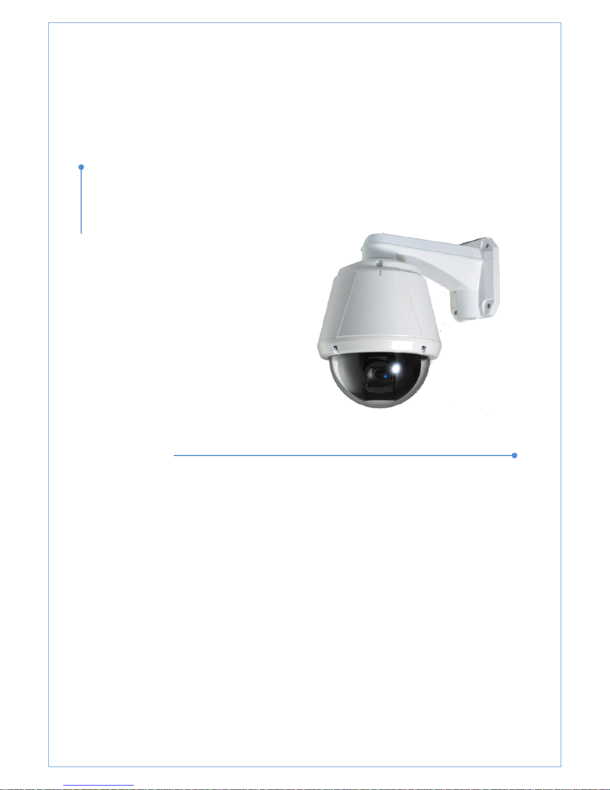
HTP‐T2M20WXI
2.0MegapixelIPPTZCamera
X20ZoomCMOS

2.0 Megapixel IP X20 PTZ Camera User Manual
2/67
Safety Precaution
Make sure to turn off the power before installing camera.
Do not install under the direct sunlight or in dusty areas.
Make sure to use the product within the temperature and humidity specified in the
specification.
Do not operate the product in presence of vibrations or strong magnetic fields.
Do not put electrically conducting materials in the ventilation hole.
Do not open the top cover of the products. It may cause a failure or electric shock on the
components.
To prevent from overheating, make sure to keep the distance at least 10cm from the
ventilation hole.
Make sure proper voltage before connecting the power.
We appreciate your purchasing Megapixel IP PTZ camera.
Before installing the product, please read the following with care
.

2.0 Megapixel IP X20 PTZ Camera User Manual
3/67
Table of Content
1. Introduction .......................................................................................................................... 4
About this manual ............................................................................................................... 4
Features ............................................................................................................................ 4
Product and Accessories ...................................................................................................... 6
Part Names and Functions .................................................................................................... 7
System Connections ............................................................................................................ 8
2. Installation .......................................................................................................................... 10
DIP Switch Setup .............................................................................................................. 10
Installation Camera with Brackets ........................................................................................ 12
Wiring/Cabling & Connecting .............................................................................................. 14
Check if it works ............................................................................................................... 17
3. System Operation ................................................................................................................ 18
Remote Video Monitoring ................................................................................................... 18
Initialization of IP address ................................................................................................... 21
4. Remote Configuration .......................................................................................................... 22
Using Web Brower ............................................................................................................. 22
System Configuration ......................................................................................................... 23
Video Configuration ........................................................................................................... 27
Audio Configuration ........................................................................................................... 32
Network Configuration ........................................................................................................ 34
Serial Configuration ........................................................................................................... 40
Event Configuration ........................................................................................................... 43
PTZ Configuration ............................................................................................................. 49
Record Configuration ......................................................................................................... 5 4
User Configuration ............................................................................................................ 61
Camera Configuration ........................................................................................................ 63

2.0 Megapixel IP X20 PTZ Camera User Manual
4/67
1. Introduction
About this manual
This User Manual provides information on operating and managing the megapixel IP PTZ camera. The
Manual includes instructions of installation, operation and configuration of megapixel IP PTZ camera as well
as how to make troubleshooting.
Features
This product is a megapixel PTZ network-based camera with remote live monitoring, audio monitoring and
control via an IP network such as LAN, ADSL/VDSL, and Wireless LAN.
Video
z Highly efficient compression algorithm, H.264 & MJPEG support
z Wide range of transmission rates: 32kbps ~ 10mbps
z Various transmission modes: CBR, VBR
z Motion detection
Audio
z Multi-transmission mode:
Simplex (IP PTZ camera Æ Client PC or Decoder, Client PC or Decoder Æ IP PTZ camera), Full Duplex
Network
z Fixed IP & Dynamic IP (DHCP) support
z 1:1, 1:N support
z Multicasting
z Various types of Protocol support : TCP/IP, UDP, Multicast, DHCP, SMTP, HTTP, SNMP, RTP, RTSP
z ONVIF, PSIA compliant
Serial Data
z RS-485 support
z Data pass-through mode : Serial data communication between megapixel IP PTZ camera and Decoder
Sensor and Alarm
z Support direct connections of external sensor and alarm devices
z Event Alarm notification.
z If an external sensor is activated, camera can be set to move to the corresponding Preset position.

2.0 Megapixel IP X20 PTZ Camera User Manual
5/67
User Interface
z Diagnose and upgrade through dedicated program called True Manager
z System configuration using Internet Explorer
High Reliability
z Reliable embedded system
Powerful Pan/Tilt Functions
z Max. 360°/sec high speed Pan/Tilt Motion
z Using Vector Drive Technology, Pan/Tilt motions are accomplished in a shortest path. As a result, time to
target view is reduced dramatically and the video on the monitor is very natural to watch.
z For jog operation using a controller, since ultra slow speed 0.05°/sec can be reached, it is very easy to
locate camera to desired target view. Additionally it is easy to move camera to a desired position with
zoom-proportional pan/tilt movement.
Preset, Pattern, Swing, Group
z MAX. 128 Presets are assignable and characteristics of each preset can be set up independently,
z Max. 8 set of Swing action can be stored. This enables to move camera repetitively between two preset
positions with designated speed.
z Max. 4 of Patterns can be recorded and played back. This enables to move camera to follow any
trajectory operated by joystick as closely as possible.
z Max. 8 set of Group action can be stored. This enables to move camera repetitively with combination of
Preset or Pattern or Swing. A Group is composed of max. 20 entities of Preset/Pattern/Swings.
PTZ(Pan/Tilt/Zoom) Control
z With RS-485 communication, max. 255 of cameras can be controlled at the same time.
z Pelco-D or Pelco-P protocol can be selected as a control protocol in the current version of firmware..
Easy Installation and Perfect Outdoor Environment Compatibility
z Fans and heaters are built-in in camera for cold and hot temperature environment. Also idealistic
mechanical design protects camera from water and dust
z It is easy to install and maintain camera with terminal for cable connection in brackets.
2.0 Megapixel IP X20 PTZ Camera User Manual
6/67
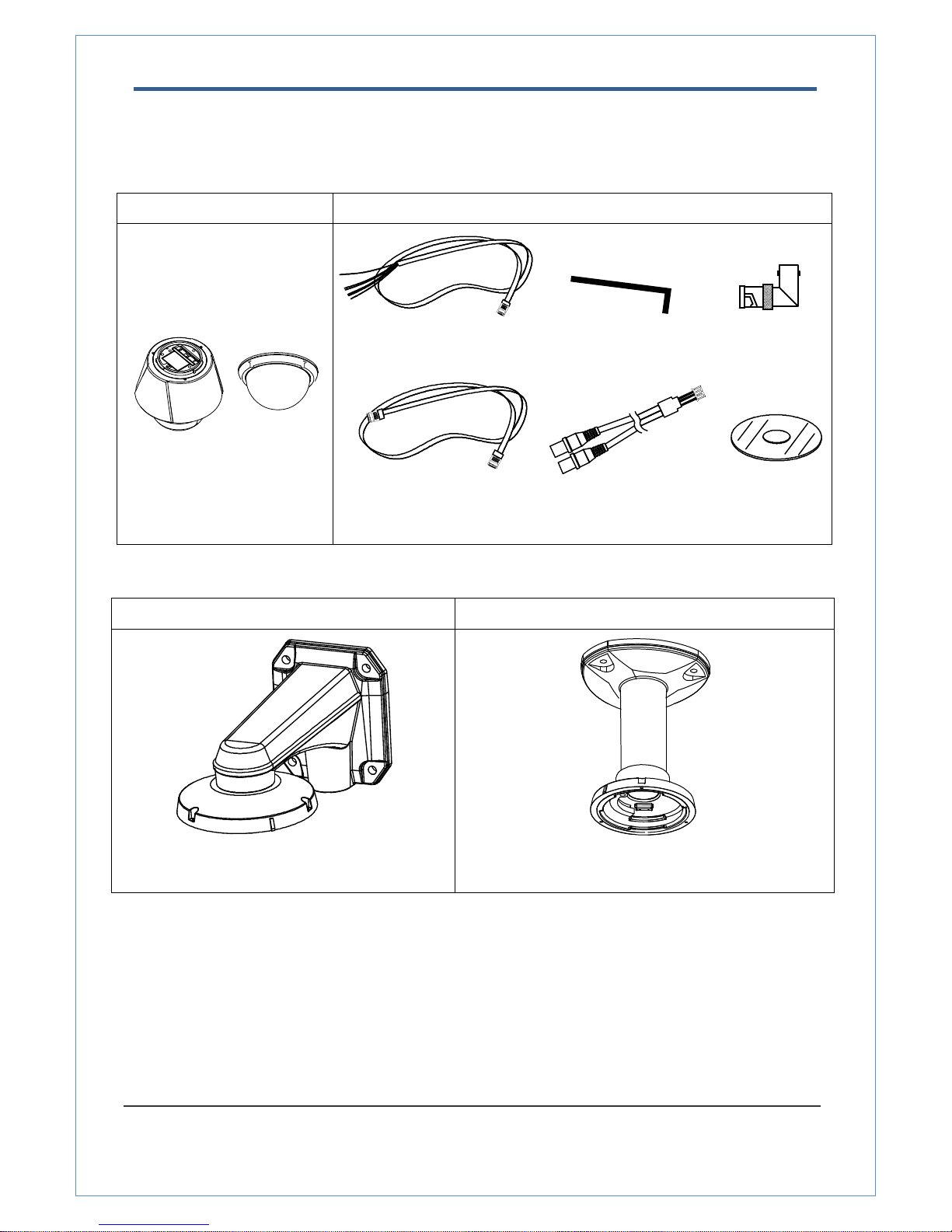
Product and Accessories
Note: Mount Brackets are optional.
z Wall Mount Bracket z Ceiling Mount Bracket
[Screws : Torx Secrew M4×18, Hex Lag #14×50] [Screws : Torx Screw M4×18, Anchor Bolt 3/8"×70]
z Main body & Dome Cover
z Accessories
Main Cable Wrench Driver 2EA of BNC
Cross LAN Cable Audio Cable CD
2.0 Megapixel IP X20 PTZ Camera User Manual
7/67
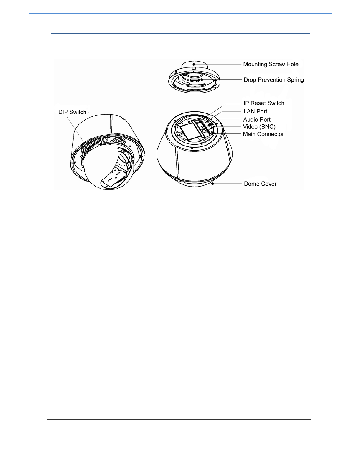
Part Names and Functions
• Dome Cover Do not detach protection vinyl from dome cover before finishing all
installation process to protect dome cover from scratches or dust.
• DIP Switch Sets up camera ID and protocol.
• Drop Prevention
Spring
This part keeps the camera from dropping during installation and
maintenance. After install the Bracket, please, hang the spring to
the drop prevention hook of main body as shown in picture for
further tasks.
• Mounting Screw
Hole
This hole is for screws that assembles the main body with a
bracket.
• IP Reset Switch Reset its network configuration to the factory defaults. You will lose
all data that had been entered previously. To initialize the system
to the factory default, press the reset button for more than 5
seconds.
• LAN Port Used for the Ethernet connection
• Audio Port Used for the audio in/out connection.
• Video (BNC) Used for the composite video out or HD-SDI video out connection
according to models
• Main Connector Used for the power wire, the RS-485 communication cable, alarm
in/out connection cable.
①
2.0 Megapixel IP X20 PTZ Camera User Manual
8/67
or
or
or
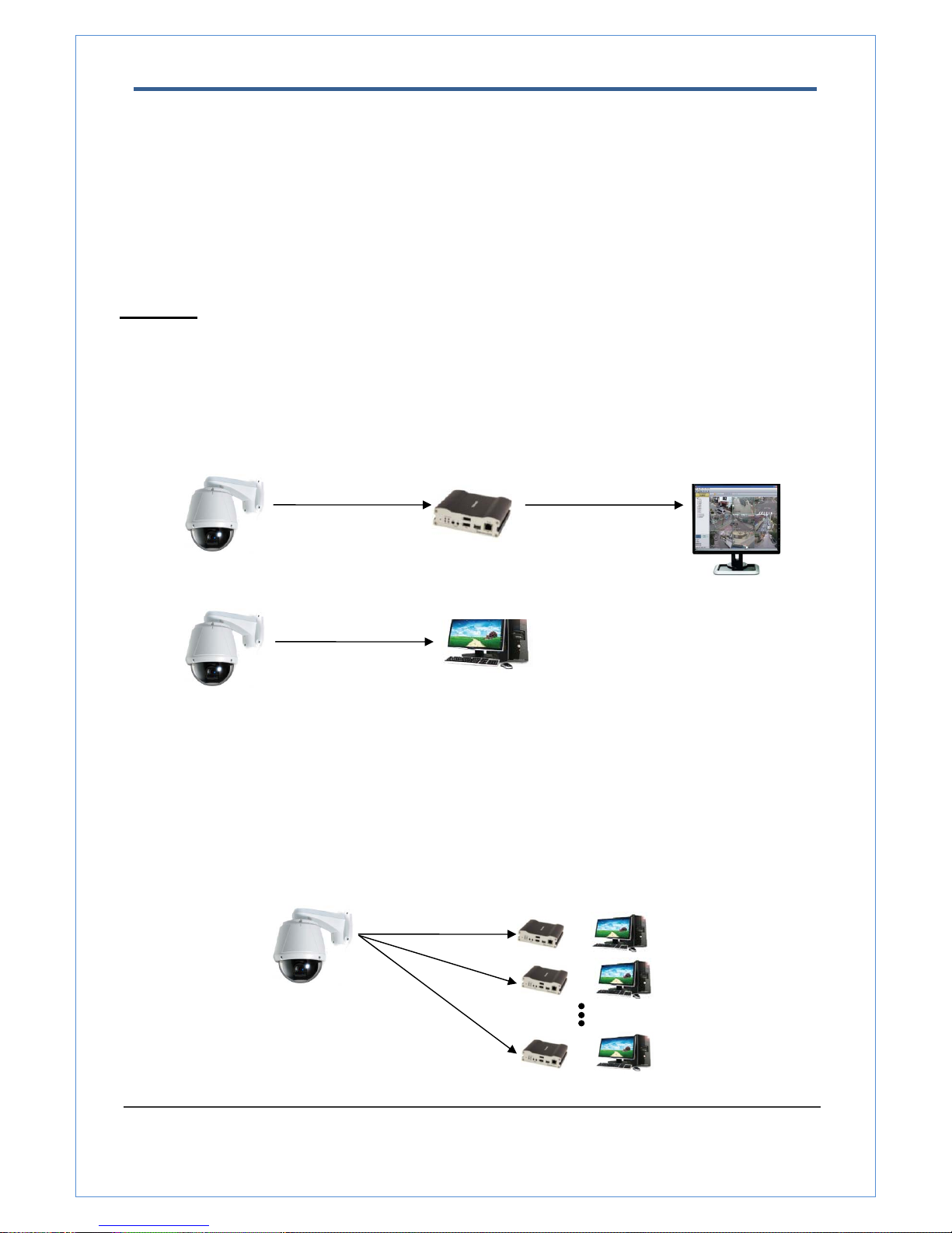
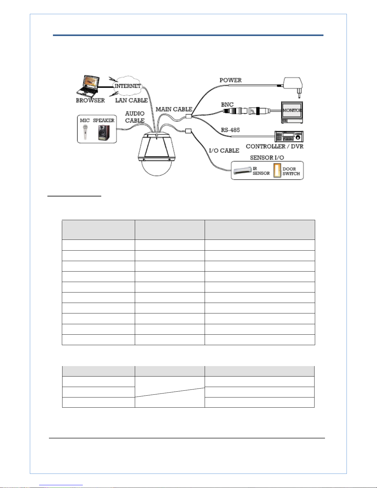
System Connections
IP Camera can be connected in either 1 to 1 connection where one camera is connected to one PC client or a
decoder system or 1 to many connections where one camera can be connected to several PCs and decoder
systems. (video server can work as a video decoder which takes the data from a video server or IP camera,
decodes and outputs analog video.)
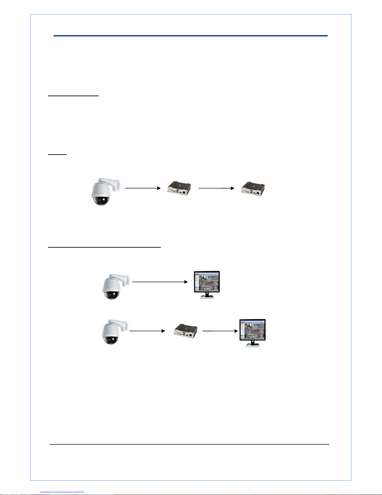
Topology
Generally, megapixel IP Camera and PC or a decoder is connected in 1-to-1 mode or 1-to many configuration.
z 1:1 Connection .
One camera is installed at a site where video images are transmitted. A PC or a decoder is installed at a
central location to receive and view the video images on an analog monitor. Audio and serial data are
transferred in either direction.
z 1:N Connection .
Site
Remote Center (Decoder)
Remote Center
Site
Remote Center (PC SW)
Site
Remote Center
2.0 Megapixel IP X20 PTZ Camera User Manual
9/67
In this configuration, a site can be monitored from many remote central locations. Although up to 64 PCs or
decoders can be connected to one camera, in the real network environment, network bandwidth can limit the
maximum connections. Functionally, the central monitoring system (CMS) software provided can replace the
decoder.
Multicast Mode
If the network supports multicasting, a large number of decoders can be used to receive video effectively from
a camera using a single streaming of video and audio. However, multicast mode is possible only when
network environment supports multicast.
Relay
Video and audio data can be retransmitted from a center to another center. The arrangement is useful when
the network bandwidth to the site is limited while there are more than one center want to monitor the site.
VMS (Video Management System)
VMS (Central Monitoring System) is a Window-based remote monitoring program in order to monitor or
control video, audio, and events in real time from several IP cameras or video servers. Please refer to the
VMS User Manual for more in detail.
Site
Remote Center
Site
Center 1(Decoder)
Center 2 (Decoder)
Site
Remote Center (Decoder)
CMS
2.0 Megapixel IP X20 PTZ Camera User Manual
10/67
2. Installation
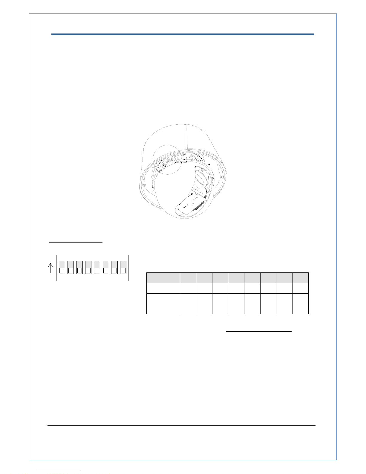
DIP Switch Setup
When you control the camera through RS-485, before installation, you should set the DIP switches to
configure the camera ID, communication protocol.
Camera ID setup
ON
ON
12345678
z ID numbers of camera are set up with binary numbers..
See the examples shown below
Pin 1 2 3 4 5 6 7 8
ID Value 1 2 4 8 16 32 64 128
ex) ID=5 on off On off off off off off
ex) ID=10 off on Off on off off off off
z The camera ID range is 1~255. Camera ID must not be 0
.
z Factory default of Camera ID is 1.
z Match the camera ID with Cam ID setting of your DVR or Controller
to control the camera.

2.0 Megapixel IP X20 PTZ Camera User Manual
11/67
Communication Protocol Setup
1234
ON
ON
z Select the appropriate Protocol with DIP switch combination.
Switch State
Protocol/Baud rate
P0
(Pin 1)
P1
(Pin 2)
P2
(Pin 3)
OFF OFF OFF PELCO-D, 2400 bps
ON OFF OFF PELCO-D, 9600 bps
OFF ON OFF PELCO-P, 4800 bps
ON ON OFF PELCO-P, 9600 bps
Otherwise Reserved
z If you want to control using DVR or P/T controller, their protocol must
be identical to camera. Otherwise, you can not control the camera.
z Adjust the DIP switch after turning off the camera. If you changed the
camera protocol by changing the DIP switch, the change will be effective
after you reboot the camera.
z Factory default of protocol is “Pelco-D, 2400 bps”.
2.0 Megapixel IP X20 PTZ Camera User Manual
12/67
Installation Camera with Brackets
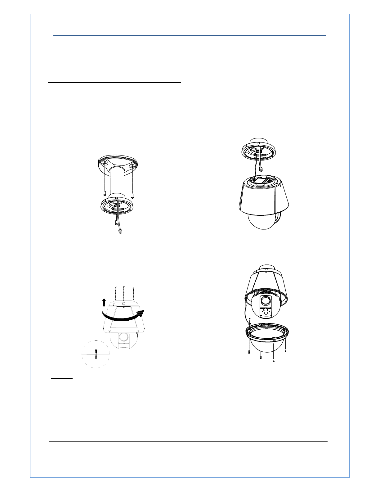
Installation using Ceiling Mount Bracket
① Remove the ceiling tile from the ceiling and cut a
hole whose diameter is 30~40mm on the ceiling tile
to pass the wire(s) and cable(s) through to the
upside of the ceiling. (In case of the wiring and
cabling through the mounting surface only) Then
prepare the ceiling mount bracket. Pull the wire(s)
for the system as below. (Anchor Bolt 3/8"×70)
② Hook up “Drop Prevention Spring” on main body
to prevent camera from unexpected drop and pull
the wire(s) and cable(s) for the system as below
③ Line up the mold lines and assemble main body
to mount adaptor and turn it. And assemble the
main both with the camera mount adaptor with
the screws. (Torx screw M4X18). Please make
sure the screws are tightly assembled for
waterproof.
④ Screw the dome cover to the main body and
remove the protection vinyl from the dome cover.
Notice
z Before starting the installation, make sure that the Camera ID and Protocol are set up properly.
z To adjust the installation height from the mounting surface, the pipe and coupler should be needed
between the surface mount part of the ceiling mount bracket and the camera mount part of the ceiling
mount bracket. Note that they are not supplied by the manufacturer.
2.0 Megapixel IP X20 PTZ Camera User Manual
13/67
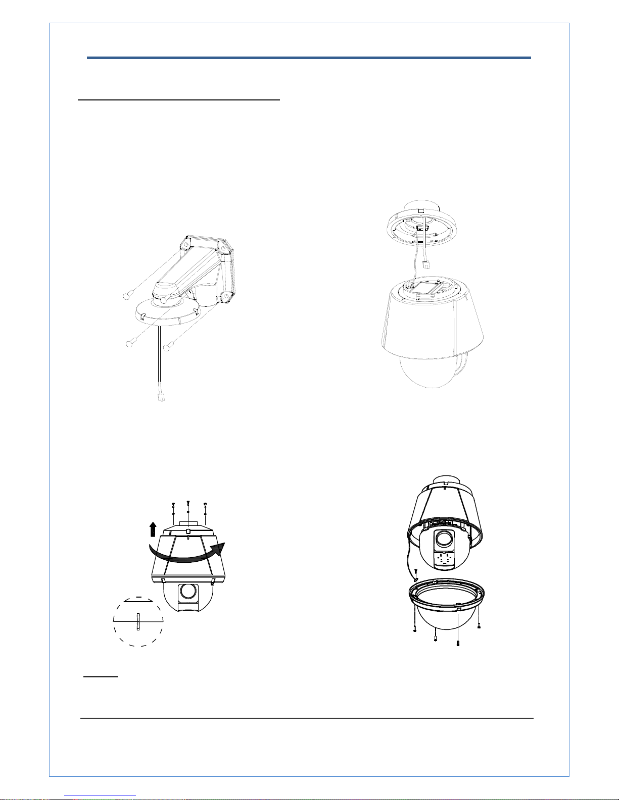
Installation using Wall Mount Bracket
① Make a hole whose diameter is 30~40mm on the
mounting surface to pass the wire(s) and cable(s)
through the mounting surface. (In case of the wiring
and cabling through the mounting surface only)
Then prepare the wall mount bracket. Pull the
wire(s) and cable(s) for the system as below. Attach
the wall mount bracket to the mounting surface.
(Hex Lag #14×50)
② Hook up “Drop Prevention Spring” on main body to
prevent camera from unexpected drop and pull the
wire(s) and cable(s) for the system as below.
③ Line up the mold lines and assemble main body to
mount adaptor and turn it. And assemble the main
both with the camera mount adaptor with the screws.
(Torx screw M4X18). Please make sure the screws
are tightly assembled for waterproof.
④ Screw the dome cover to the main body and
remove the protection vinyl from the dome
cover.
Notice
z Before starting the installation, make sure that the Camera ID and Protocol are set up properly.
2.0 Megapixel IP X20 PTZ Camera User Manual
14/67
Wiring/Cabling & Connecting
Port Description
z Main Cable
Port Pin Number (RJ45) Connector / Wire Color Signal
1
Black
RS485 +
2
Brown
RS485 −
3
Red
DC 12V
4
Orange
Ground
5
Yellow
OUT COM (Relay Output Common)
6
Green
OUT 2 (Relay Output 2)
7
Blue
OUT 1 (Relay Output 1)
8
Violet
IN COM (Sensor Input Common)
9
Gray
IN 1 (Sensor Input 1)
10
White
IN 2 (Sensor Input 2)
z Audio Cable
Port Pin Number Connector/ Wire Color Signal
1 RCA (Yellow) Audio IN
2 Audio GND
3 RCA (White) Audio OUT

2.0 Megapixel IP X20 PTZ Camera User Manual
15/67
Connecting Power
1. Carefully check the voltage and current capacity of the rated power. The rated power is indicated in the
back of main unit.
2. After confirming the power source, connect power adaptor and connect the 12V DC connector to the
system
z For the DC input models, be careful with the polarity of DC power. The system should be
permanently damaged by wrong DC input.
z In case that the length of the power wire is very long, there may be voltage drop and the system may
not work properly. Make the length of the power wire as short as possible.
Connecting Network
1. Plug network cable to Ethernet port (RJ-45 network port).
Connecting Video
1. To display video through the composite or HD-SDI port, connect each port to a monitor using BNC
coaxial cable
2. Set Enable Preview option “ON” on the Video tab of web page.
(Please refer to the Video Configuration part)
z Especially in case of using HD-SDI, video cannot be viewed if BNC coaxial cable is not used.
z In case that video transmission distance is long, video data may not be transmitted due to a
reduction in the video signal. In order to prevent it, install a repeater in the middle.
z In case of using HD-SDI, video can be viewed only on a HD-SDI monitor.
Connecting Audio
Audio is full-duplex. It is possible to set the mode as Tx-only, Rx-only or Tx-Rx.
1. Connect audio input and output ports to audio devices accordingly.
2. The Audio signal required is line level, so an audio equipment with an amp, mixer or other amplifier should
be used.
2.0 Megapixel IP X20 PTZ Camera User Manual
16/67
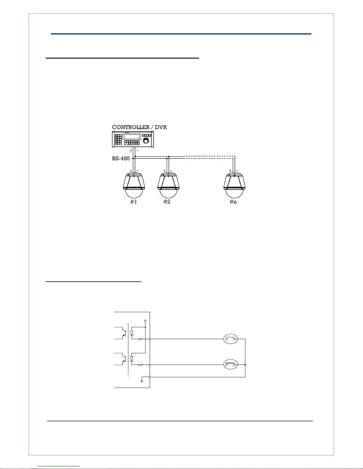
Connecting Serial Port (RS-485 Communication)
z For PTZ control, connect the cable(s) to your keyboard or DVR. To connect multiple cameras to a single
controller, RS-485 communication should be connected in parallel as shown below. If you are connecting
a single camera to a controller, terminate the camera. When connecting more than one camera to a
single controller, terminate the last camera on the communication line. The last camera means the
camera farthest in cable length from the controller. Note that the total length of the communication cable
between a controller and the camera(s) on the same communication line must be less than 1.2Km.
z RS-485 of Megapixel PTZ Camera can be connected to external equipment such as PT receiver etc. PC
client can send PT commands to the external equipment via the serial port.
When a decoder system instead of PC client is connected to Megapixel PTZ Camera, the serial port and
that of the decoder system works in pass-through mode. That is, data from at one port is delivered to the
other port, vice versa
Connecting Sensor and Alarm
Connect sensor and alarm devices to corresponding terminals accordingly.
z Sensor Input
IN COM
IN 1
IN 2
Sensor 1
Sensor 2
V+
2.0 Megapixel IP X20 PTZ Camera User Manual
17/67
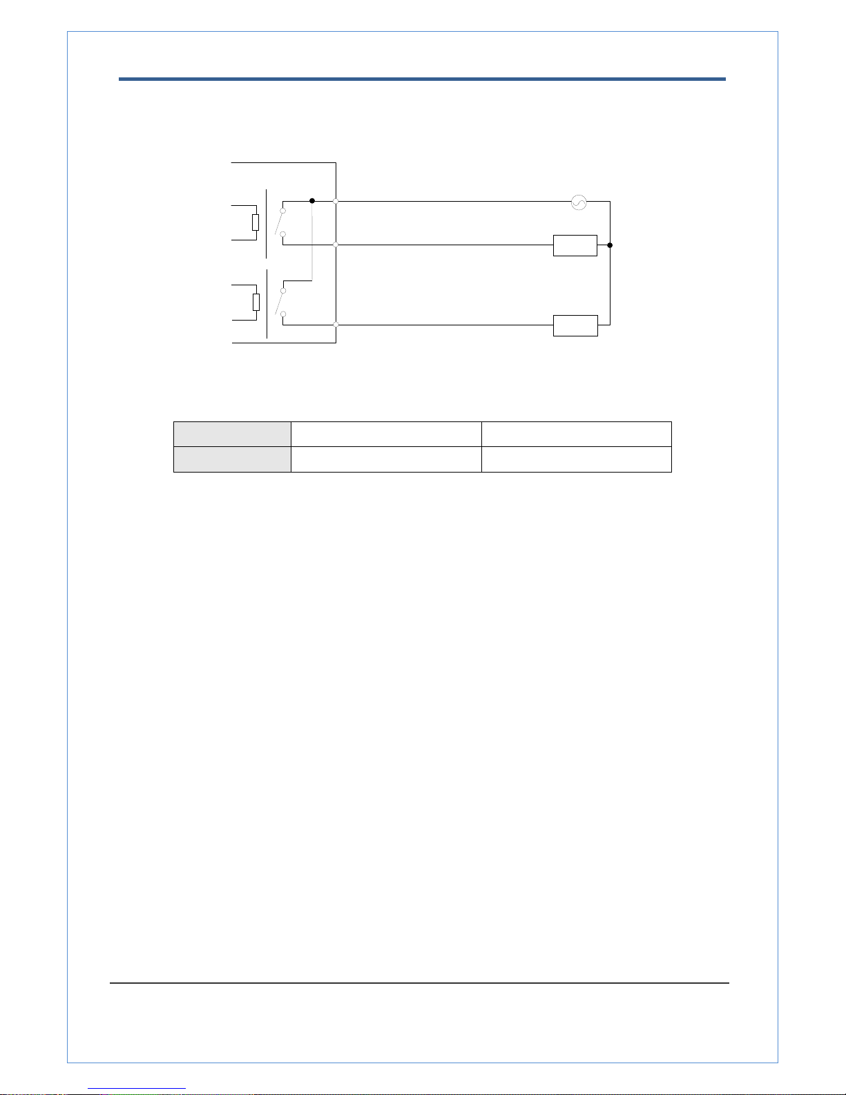
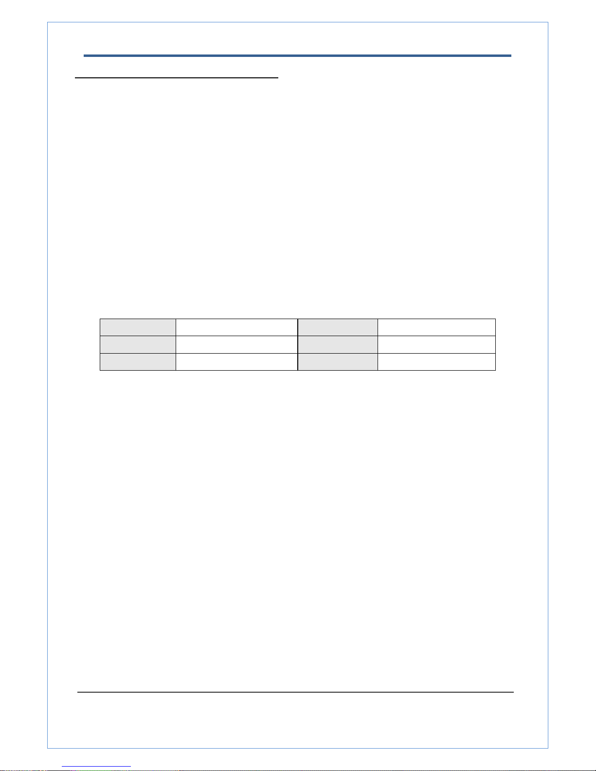
z Relay Output
Maximum allowable electrical load of relay is shown bellow table.
Drive Power DC Power AC Power
Max. Load Max DC 24V, 1A Max AC 125V, 0.5A
Check if it works
Once the power is supplied to the camera, it will start booting. The system will boot up to an operating mode
after approximately 40-60 seconds. The green LED on the Ethernet port will flash indicating the system is
ready.
The software provided in the CD called True Manager allows you to check the IP address and other network
details of the camera. Please refer to the True Manager manual for instructions on how to find the IP address
of the camera and change it if required.
OUT 1
AC or DC
LOAD
Internal
OUT 2
LOAD
OUT COM
2.0 Megapixel IP X20 PTZ Camera User Manual
18/67
3. System Operation
Remote Video Monitoring
There are two ways to monitor video when the center system and Megapixel PTZ Camera are connected. In
order for a proper operation, an IP address must be set accordingly. Please refer to True Manager in Chapter
3 or Remote Setting in Chapter 4 for further details.
Default ID : admin Default Password : 1234
.
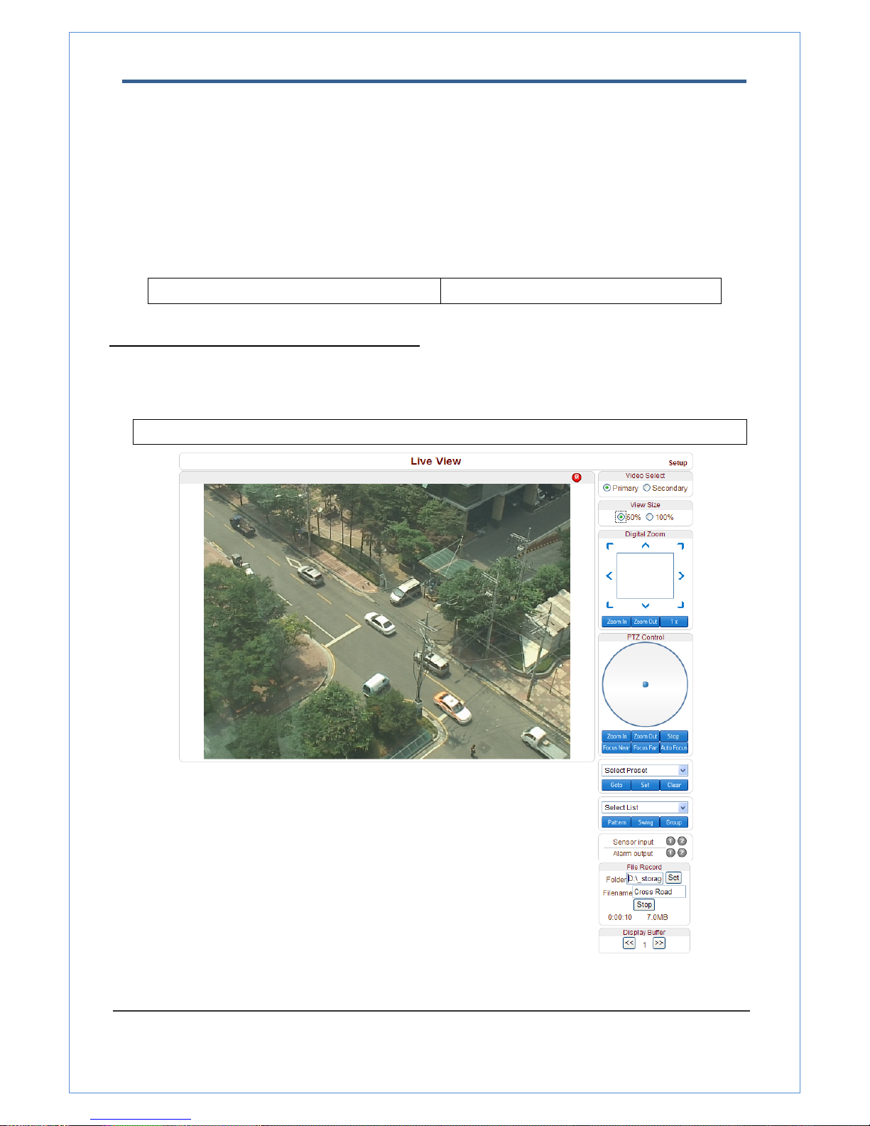
Video Monitoring using Internet Explorer
Open Internet Explorer and enter camera’s IP address. The system will ask for confirmation to install Active-X
control. Once authorized, the Internet Explorer will start to display video images from camera as shown below.
Default IP Address : http://192.168.10.100
2.0 Megapixel IP X20 PTZ Camera User Manual
19/67
z Video Select
Select the Video stream to be viewed: Primary or Secondary
This camera is capable of dual streaming; primary streaming and secondary streaming.
Video will be displayed according to the resolution set on video configuration. If dual streaming (“Use
Dual Encode” Menu in Video page) is not activated, secondary video is not available
z View Size
Adjust the Screen size
Screen size is initially adjusted according to the compression resolution. If you click 50% icon, the whole
screen size will be reduced to half size.
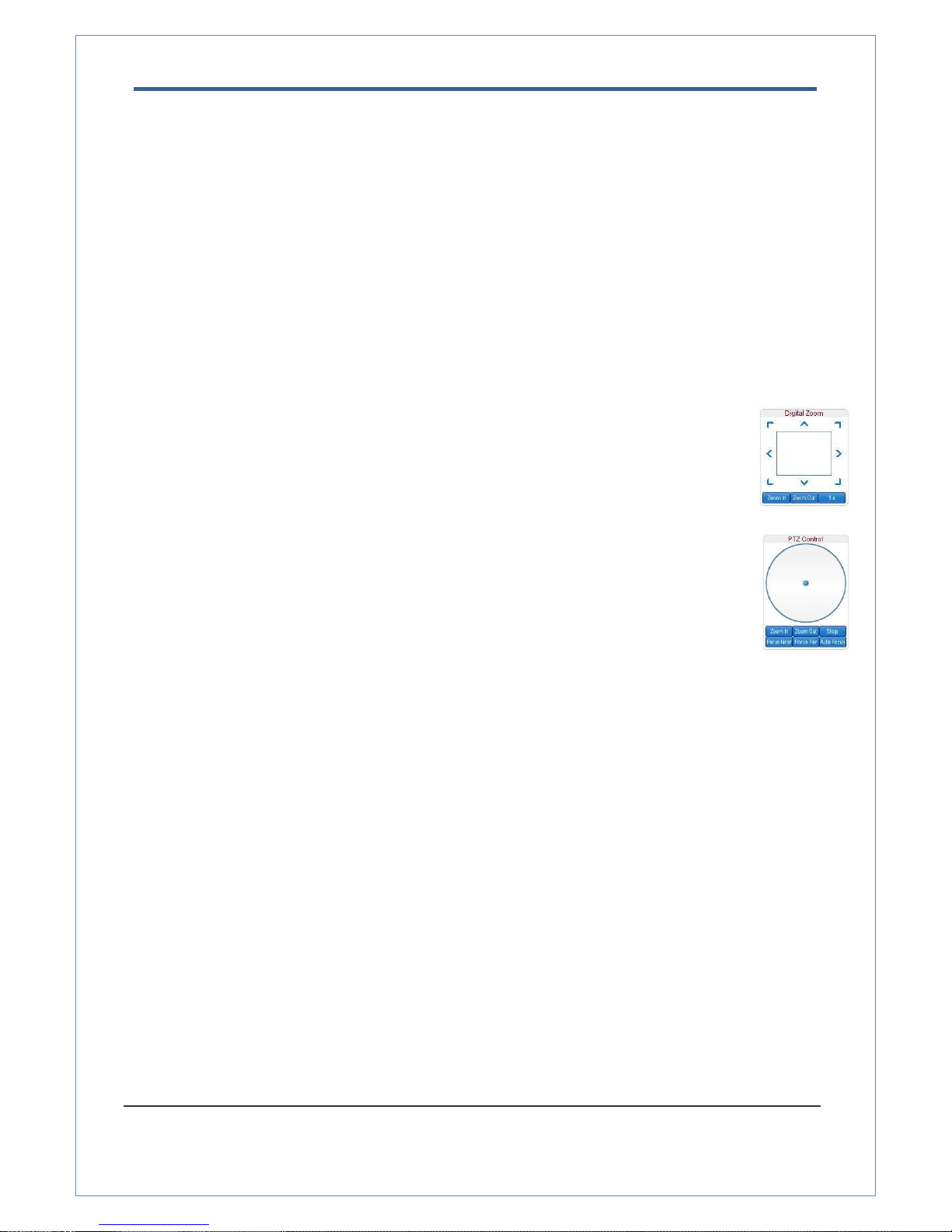
z Digital Zoom
Control the Digital zoom on the screen
The more the camera zooms in, the smaller the square of control panel is. Position of the
image can be changed by moving position of the square.
If you press x1, the screen will return to the normal size.
z PTZ Control (Optical Zoom & Digital zoom built-in the camera)
Control PTZ and PTZ Control Panel is used for controlling external PTZ devices when the
external PTZ devices are connected through serial port.
It is possible to make zooming control by Zoom in/out buttons of PTZ control Panel (In
order to use digital zoom, select Digital zoom ON in the Camera tab)
- Stop
Stop on-going PTZ action.
- Focus Near, Focus Far, Auto Focus
Adjust the focus of the lens
z Select Preset
Set preset position and move to the specific preset position.
- Goto: Move to the selected preset entry if the preset entry is set.
- Set: Set the current position to the selected preset entry.
- Clear: Delete the selected preset entry.
z Select List
Run a selected Pattern or Swing or Group.
After selecting an entry in the list, Pattern, Swing or Group button can be pressed. Then, corresponding
operation is executed for the selected list.
(Please refer to the PTZ tab to set Pattern, Swing and Group)
2.0 Megapixel IP X20 PTZ Camera User Manual
20/67
z Sensor Input
Display the status of the sensor in real time.
This camera supports two sensor inputs. When the sensor of the camera is working, the sensor light
turns red.
z Alarm Output
Operate the alarm device by pressing the number icon
This camera supports two alarm outputs. A number icon indicates status of the alarm device.
z Snapshot
Capture video images and store them as BMP or JPEG files.
z Talk
Transfer audio from PC’s mic to the camera.
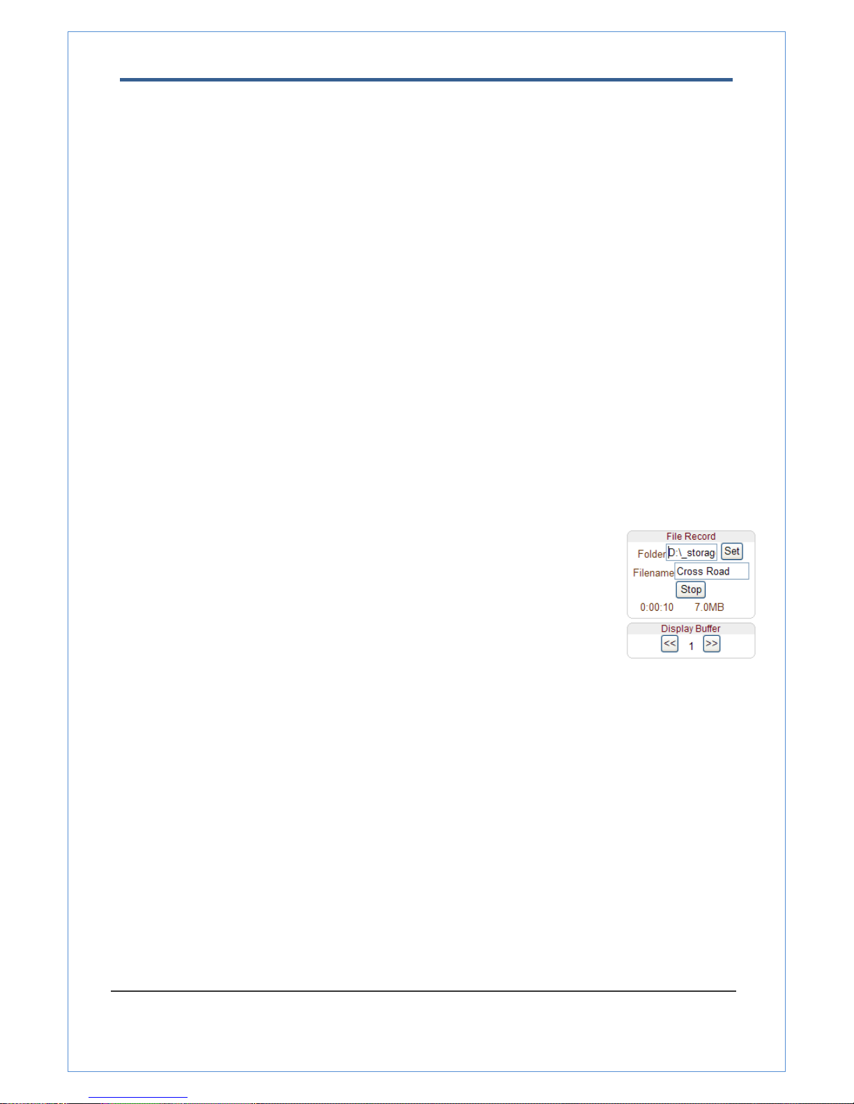
z File Record
Recording to an AVI file on Live View page is available. AVI files are generated in the specified folder or
in specified file name on the PC where web browser is running.
1. Press “Set” button to select folder or create a new folder. Enter the file name on
Filename field.
2. Press “Start” button to start to record.
3. Press “Stop” button to stop to record.
4. AVI file named “IP address_hh_mm_ss” or “File name_IP address_hh_mm_ss”
will be generated in the specified folder depending on whether the path specified
a folder or a prefix of the file name.
z Display Buffer
Set the number of video frames to be buffered before being displayed on web browser. Larger value
results in smoother video by sacrificing the latency. A setting of 10 ~ 15 frames can be used generally for
most situations.
z Other key function
- Click to Center On-screen PTZ control
TCAM-570 series support “Click to center” as a function of on-screen PTZ control. By double clicking a
position on the video area of web viewing, it is possible to move the clicked position to the center of the
video area and zoom in.
2.0 Megapixel IP X20 PTZ Camera User Manual
21/67
Video Monitoring with Decoder System
Once camera’s IP address is set in the remote IP address section of the decoder, the decoder system will
connect to camera and start receiving the video images. Normally, a monitor connected to the decoder will
display video images
Initialization of IP address
If a system IP address is lost, the system can be reset to the system default IP address using the reset button
in the back side of the system.
1. While system is in operation, press the reset button for more than 5 seconds.
2. The system will reboot automatically
3. Once the system reboots, IP address will be set to the system default as below.
• IP mode Fixed IP • IP address 192.168.10.100
• Subnet mask 255.255.255.0 • Gateway 192.168.10.1
• Base port 2222 • HTTP port 80
 Loading...