

Hunt Electronic HTC-230S Instruction Manual

HTC-230S
SPEED DOME CAMERA
INSTRUCTION MANUAL
Hunt Electronic USA, Inc.

CAUTION
□ Never install the unit with power supplied.
- Installation with power supplied could result in electrical shock.
□ Always handle the connecting cords properly.
- Never damage or modify the connecting cords.
- Never pull on the connecting cord, expose them to extreme heat and/or
place heavy objects on top of them.
- Failure to follow these warnings could result in fire, electrical shock or
other damage or injury.
□ Never disassemble or attempt to repair or modify the unit by yourself.
- Disassembly by untrained personnel could result in serious electrical shock,
fire and/or malfunction.
□ Never use in locations where combustible materials are used.
- The unit should never be used where combustible materials, such as gases
are being used. Fire, explosion or other serious accidents could occur.
□ Never touch electrical connections with wet hands.
- Touching electrical connections with wet hands could result in serious
electrical shock.
□ Never expose the unit to water.
- If the unit becomes wet, turn off the power and unplug it immediately.
□ Never place the unit in extremes of high or low temperatures.
- Extreme temperatures will damage the unit.
- Always use within an operating range of –15°C to 50°C (5℉ ~ 122℉).
□ Always use the designated power supply.
- Failure to use the proper power supply could result in fire, electrical shock,
serious injury and/or damage.
- Always use the designated power supply.
□ Never expose the unit to impact.
- Strong impact may seriously damage the unit.
□ Never place the unit near the magnetic.
2

Table of Content
Chapter 1. Introduction of the product 4
1.1 Product Features 4
Chapter 2. How to install and connect with equipments 5
2.1 Name and function of each part 5
2.1.1 The name of each part 5
2.1.2 How to install and wiring 6
2.2 Connecting with equipments 9
2.2.1 Basic connection diagrams 9
2.2.2 Connection diagrams in detail 10
Chapter 3. How to use functions in detail 12
3.1 How to set DIP switches 13
3.1.1 How to set optional DIP switches 13
3.1.2 How to set address of DIP switches 14
3.2 How to use OSD menu 15
3.2.1 How into the ODS menu 15
3.2.2 Functional description of each menu 16
3.3 OSD(On Screen Display) menu in detail 22
3.3.1 Preset Message 22
3.3.2 Swing Message 22
3.3.3 Group message 22
3.3.4 Tour Message 23
3.3.5 Spiral SEQ Message 23
3.3.6 Alarm Message(1) 23
3.3.7 Alarm Message(2) 24
3.3.8 Error Message 24
Chapter 4. Caution in use 25
4.1 Caution in use 25
4.2 Checking and Maintenance in use 26
Chapter 5. Dimensions 27
Chapter 6. Specification 28
3
Chapter 1. Introduction of the product
1.1 Product Features
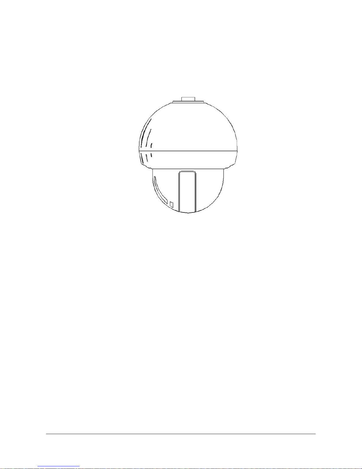
Figure 1.
1. 410K PIXELS CCD CAMERA : There is a camera that is lower illumination, High
resolution color with SONY CCD Chip.
2. HIGH MAGNIFYING ZOOM LENS : It can be realized max. 230x zoom function.
(23x Optical zoom, 10x Digital zoom)
3. MAX. 360° OF PANNING RANGE : It can be 360° per second of speed.(In preset
move)
4. MAX. 64 PRESETS MODE : It can be set preset position until 64 inputs.
5. 4CH ALARM INPUTS : It can be directly connected sensor and used with preset
owing to built-in 4-channel sensor input terminals. It can be also operated together
other equipment owing to built-in alarm output.(Relay normal output)
6. THE BUILT-IN DIGITAL FLIP FUNCTION : It can be track the moving object until
180° in vertical.
7. ADDTIONAL FUNCTIONS : It can be effectively used according to demand of user
because of included alarm, swing, group, tour, spiral surveillance, and so on.
8. IT CAN BE INSTALL FOR OUTDOORS : With the exclusive outdoor housing, it
can be installed at outdoor place.
9. RS485, RS422 OF COMMUNICATION SYSTEM : It can be controlled this product
by RS485 data or RS422 data.
4
Chapter 2. How to install and connect with equipments
2.1 Name and function of each part
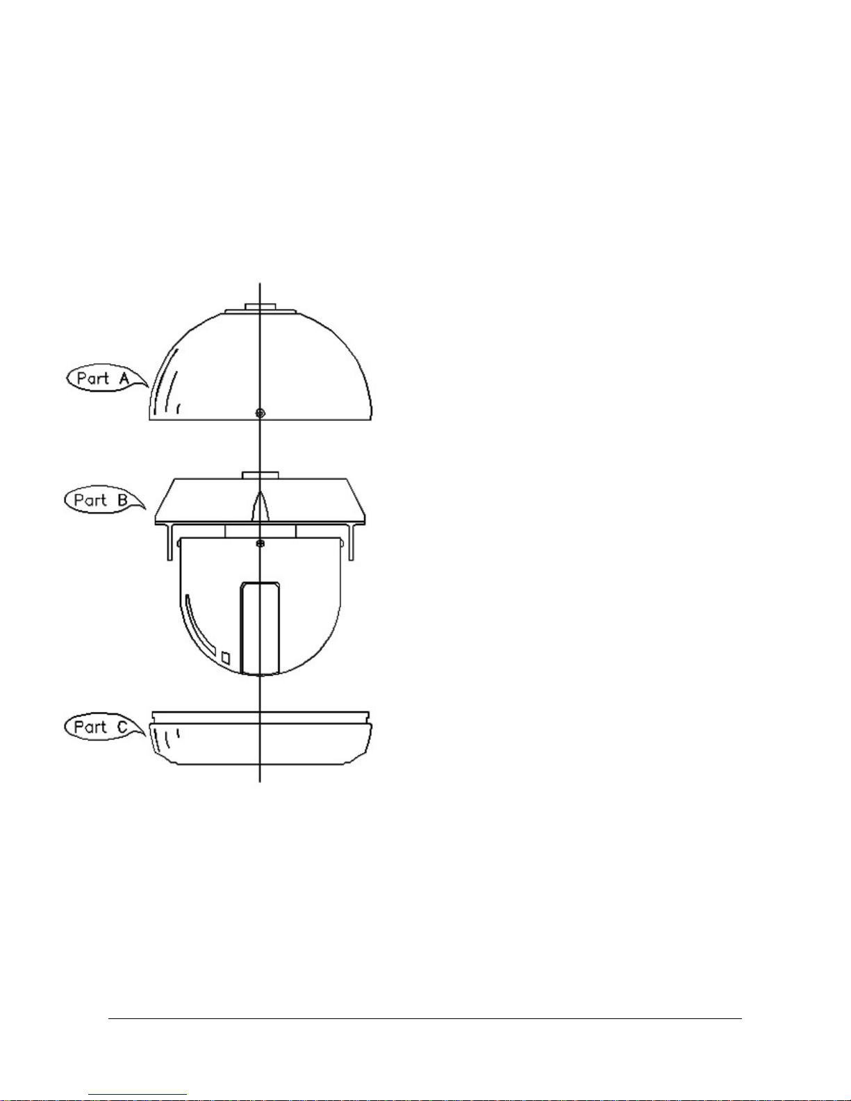
2.1.1 The name of each part
z Part A : HEAD COVER
There is a body of camera in it, connect
power cable, data cable and video-image
cable and sensors into it.
z Part B : BODY OF CAMERA
It is a main body of camera. There are
inside all of control equipments and
camera.
z Part C : LOWER COVER
Insert the body of camera into the upper
cover, then close to lower cover finally.
Figure 2.
5
2.1.2 How to install and wiring
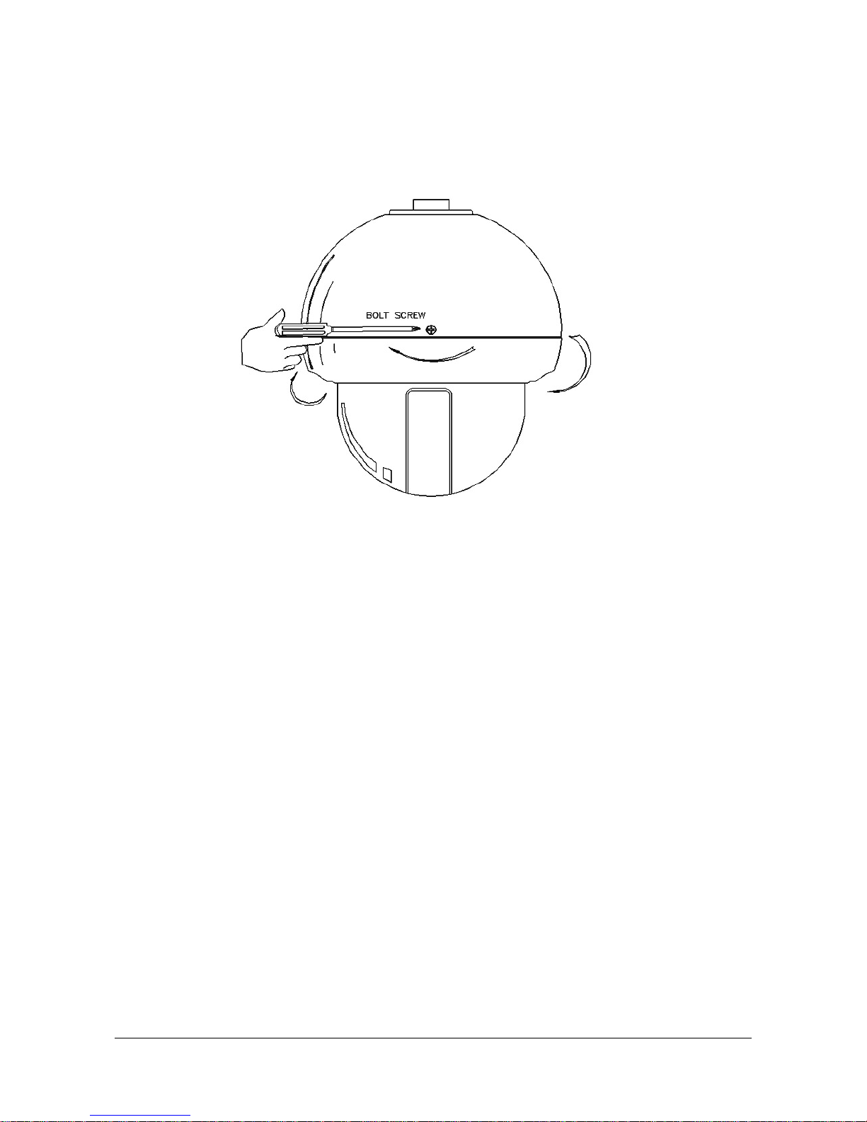
① Disassembly for installation
Figure 3
z In the installation, disassemble firstly the body of camera (Part B) from the head
cover. Loosen the bolt on the side of head cover (Part A) with a screw driver. And It
could be removed lower cover (Part C) in a way that turn left to lower cover (Part C)
softly with both hands then pull out it.
6
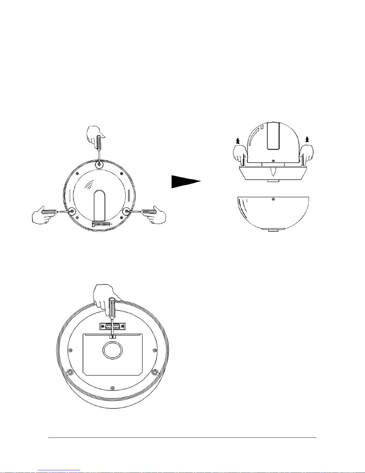
z Remove the body of camera from head cover.
z There are 3 bolts on the body of camera. They do not full pull out to prevent missing.
z Loosen three of round-headed bolts from the body of camera. If it was kept going to
loose the bolts, it can be out up to about 1 cm and it is that all. Loosen all of three
bolts, hold the rotation part of camera in both hands to pull up the body then it can be
removed.
Figure 4. Figure 5.
② Disassembly the body of camera for installation
z Open the connector cover, please
connect Data, Power, and Video cable.
z If you unscrew one of bolt(with ‘-‘ driver)
on the connector cover, it is opened.
Figure 6.
7
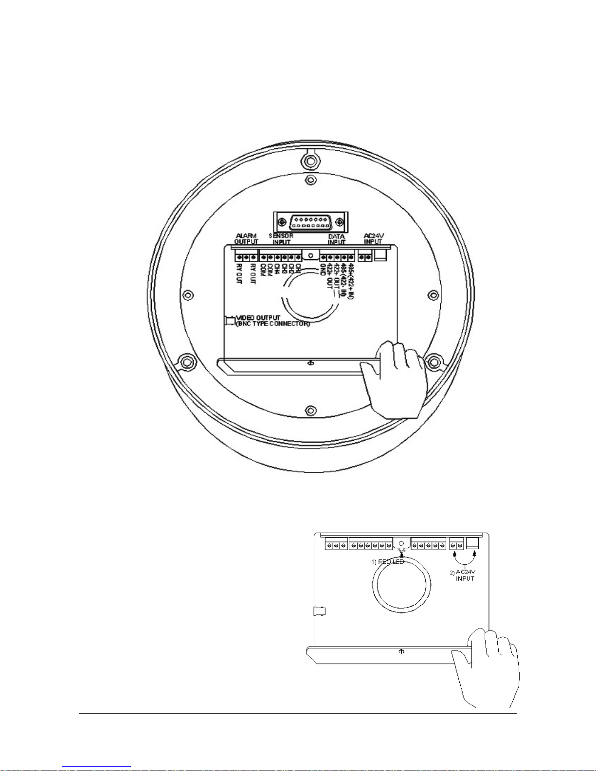
z Please be careful to wrong connect so that it is explained each connector of
function as below picture.
Figure 7.
z Did the power cable connect in normal?
z If yes, 1) the power is on, it is lit on the
RED LED in the middle of connector
2) The input power source is AC 24V
with a terminal and with a jack.
Both of them can be used.
Figure 8
8
2.2 Connecting with equipments
2.2.1 Basic connection diagrams
Figure 9.
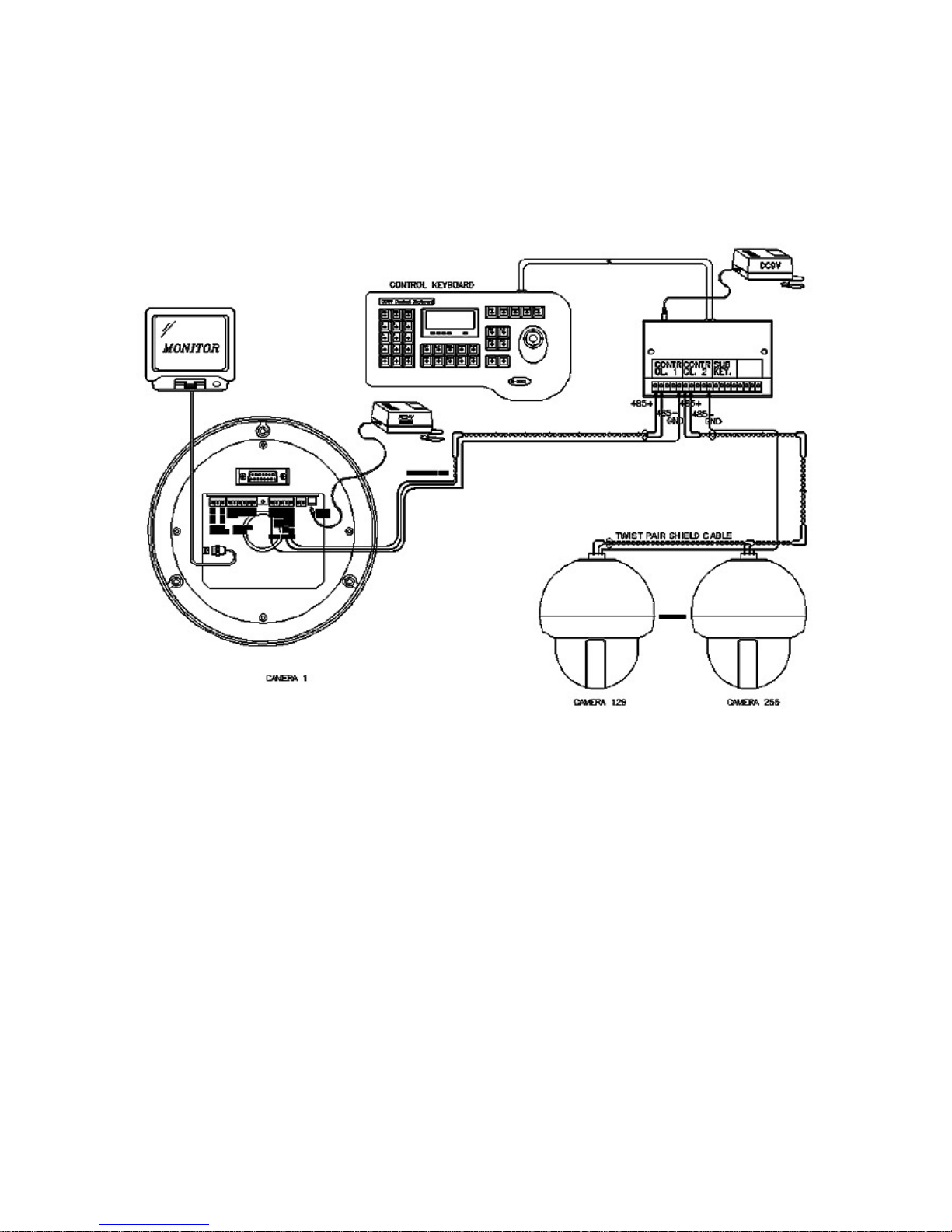
z Using exclusive keyboard controller, it can be controlled and connected with max.
255 cameras. In the data box of controller, there are two controlling ports and the
respective ports can be connected with max. 128 cameras.
z If it is used the twist pair shied cable (AWG23), can be connected until distance of
max. 1.2 Km. According to the condition of place, it is only whether to be long or to
be short.
z Firstly, it would be arranged the following:
- 1 PC of Power Adaptor using of AC 24V / 1.5A for Speed Dome Camera.
- 1 PC Of Power Adaptor using of DC 9V / 500 mA for Keyboard Controller.
- Wired Cables from monitor to camera for Image signals.
- Wired Cables from Keyboard Controller to camera for Data signals.
9
 Loading...