

Hunt Electronic HNR-04AF User Manual

USER MANUAL
04 CHANNELS
NETWORK VIDEO RECORDER
2
INSTRUCTION MANUAL
To obtain the best performance and ensure device function correctly, please read this instruction manual carefully and
completely.
FCC Compliance
USER-INSTALLER CAUTION: YOUR AUTHORITY TO OPERATE THIS FCC VERIFIED EQUIPMENT
COULD BE VOIDED IF YOU MAKE CHANGES OR MODIFICATIONS NOT EXPRESSLY APPROVED BY THE
PARTY RESPONSIBLE FOR COMPLIANCE TO PART 15 OF THE FCC RULES.
NOTE: THIS EQUIPMENT HAS BEEN TESTED AND FOUND TO COMPLY WITH THE LIMITS FOR A
CLASS A DIGITAL DEVICE, PURSUANT TO PART 15 OF THE FCC RULES. THESE LIMITS ARE
DESIGNED TO PROVIDE REASONABLE PROTECTION AGAINST HARMFUL INTERFERENCE WHEN THE
EQUIPMENT IS OPERATED IN A COMMERCIAL ENVIRONMENT. THIS EQUIPMENT GENERATES, USES,
AND CAN RADIATE RADIO FREQUENCY ENERGY AND IF NOT INSTALLED AND USED IN
ACCORDANCE WITH THE INSTRUCTION MANUAL, MAY CAUSE HARMFUL INTERFERENCE TO RADIO
COMMUNICATIONS.
OPERATION OF THIS EQUIPMENT IN A RESIDENTIAL AREA IS LIKELY TO CAUSE HARMFUL
INTERFERENCE IN WHICH CASE THE USER WILL BE REQUIRED TO CORRECT THE INTERFERENCE AT
HIS OWN EXPENSE.
THIS CLASS A DIGITAL APPARATUS MEETS ALL REQUIREMENTS OF THE CANADIAN
INTERFERENCE-CAUSING EQUIPMENT REGULATIONS.
WARNINGS, CAUTIONS & COPYRIGHT
WARINGS
TO REDUCE THE RISK OF FIRE OR ELECTRIC SHOCK, DO NOT EXPOSE THIS PRODUCT TO RAIN OR
MISTURE.
DO NOT INSERT ANY METALLIC OBJECT THROUGH VENTILATION GRILLS.
CAUTION
Explanation of Graphical Symbols
The lightning flash with arrowhead symbol, within an equilateral triangle, is intended to alert the
user to the presence of insinuated "dangerous voltage" within the products enclosure that may be of
sufficient magnitude to constitute a risk of electric shock to persons.
The exclamation point within an equilateral rhombus is intended to alert the user to the presence of
important operating and maintenance (servicing) instruction in the literature accompanying the
product.
USERS OF THE SYSTEM ARE RESPONSIBLE FOR CHECKING AND COMPLYING WITH ALL FEDERAL,
STATE, AND LOCAL LAWS AND STATUTES COIPCERNING THE MONITORING AND RECORDING OF
VIDEO AND AUDIO SIGNALS. ULTRAK SHALL NOT BE HELD RESPONSIBLE FOR THE USE OF THIS
SYSTEM IN VIOLATION OF CURRENT LAWS AND STATUTES.
COPYRIGHT
THE TRADEMARKS MENTIONED IN THE MANUAL ARE LEGALLY REGISTERED TO THEIR RESPECTIVE
COMPANIES.
CAUTION: TO REDUCE THE RISK OF ELECTRIC SHOCK.
DO NOT REMOVE COVER (OR BACK).
NO USER-SERVICEABLE PARTS INSIDE.
REFER SERVICING TO QUALIFIED SERVICE PERSONNEL.
RISK OF ELECTRIC SHOCK
DO NOT OPEN
CAUTION

3
TABLE OF CONTENTS
1 INTRODUCTION ...................................................................................................................... 4
1.1 FEATURE....................................................................................................................... 4
1.2 SPECIFICATION .......................................................................................................... 4
2 HARDWARE OVERVIEW ...................................................................................................... 8
2.1 FRONT PANEL ............................................................................................................. 8
2.2 BACK PANEL................................................................................................................ 9
2.3 ALARM TRIGGER ....................................................................................................... 9
2.4 IR REMOTE CONTROL ........................................................................................... 10
2.5 PTZ (PAN, TILT AND ZOOM) CAMERA ............................................................... 11
3 SYSTEM SETUP ..................................................................................................................... 12
3.1 MENU SETUP INTERFACE(GUI) ........................................................................... 12
3.2 LIVE VIEWING AND POP-UP MENU .................................................................... 14
3.3 CAMERA SETUP ........................................................................................................ 17
3.4 RECORD SETUP ........................................................................................................ 22
3.5 ALARM SETUP ........................................................................................................... 23
3.6 NETWORK SETUP .................................................................................................... 25
3.7 AUTHORITY SETUP ................................................................................................. 29
3.8 DISK MANAGEMENT ............................................................................................... 31
3.9 SYSTEM SETUP ......................................................................................................... 32
4 NVR PLAYBACK .................................................................................................................... 37
4.1 TIME SEARCH ........................................................................................................... 38
4.2 EVENT SEARCH ........................................................................................................ 38
4.3 BACKUP ....................................................................................................................... 39
4.4 SYSTEM LOG ............................................................................................................. 40
5 BACKUP PLAYBACK ........................................................................................................... 41
5.1 MAIN SCREEN SETTING......................................................................................... 41
5.2 PLAYBACK OPERATION ........................................................................................ 44
6 NETWORK VIEWING & PLAYBACK ............................................................................... 47
6.1 IP ADDRESS SETUP ON PC SITE ........................................................................... 47
6.2 OPTIONAL MICROSOFT INTERNET EXPLORER SETUP .............................. 48
6.3 LOGIN .......................................................................................................................... 51
6.4 REMOTE CONTROL ................................................................................................. 52
6.5 CONFIGURE ............................................................................................................... 57
APPENDIX A: RECORDING TIME LAPSE (HOURS) ............................................................. 68
APPENDIX B: HDD COMPATIBLE TABLE .............................................................................. 69
APPENDIX C: ERROR MESSAGE LIST .................................................................................... 71

4
1 INTRODUCTION
1.1 FEATURE
H264 decompression format support.
Real-time Display & Playback
Support Mega Pixel Camera for each channel.
Support CMS (Central Management System)
Audio Backup / Audio Streaming.
Graphic User Interface ( GUI )
Support time-point backup function under Ethernet remote control mode. User
can select any time period to process backup from remote side.
Support time-search & event-search function under Ethernet remote control
mode.
Up to four online clients for independent remote control; individual live-time,
play-back & time-search function available
Support PPPoE/ Static/ DHCP IP & DDNS.
Powerful mobile surveillance function, support i-Phone & Android
Support log function
1.2 SPECIFICATION
VIDEO
MODE
Multiplex
DISPLAY CHANNEL
4CH
SUPPORT IP CAM RESOLUTION
Up to 1600 x 1200 (2 M-pixel)
DISPLAY FRAME RATE
Up to 30 FPS @ NTSC per CH
SPLIT SCREEN
1, 4
VIDEO OUTPUT (VGA)
Yes
AUDIO
AUDIO OUTPUT
Phone Jack × 1
AUDIO INPUT
Phone Jack × 1
AUDIO BACKUP
Yes
AUDIO STREAMING
Yes
RECORDING
COMPRESSION TYPE
H.264
RECORDING RATE
Up to 30 FPS @ NTSC per CH

6
RECORDING MODE
Manual / Schedule / Alarm
PLAYBACK & SEARCH
PLAYBACK SPEED
Fast Forward X2 X4 X8 X16 X32 X64
Fast Backward X2 X4 X8
Frame by Frame Playback
Pause
TIME SEARCH
Yes
EVENT SEARCH
Yes
OSD & CONTROL INTERFACE
ON SCREEN DISPLAY & SETUP
Time / Date / Setup Menu
GRAPHIC USER INTERFACE
(GUI)
Yes
MOUSE
Yes
IE BROWSER
Yes
PLAYER
Yes
STORAGE & BACKUP DEVICE
INTERNAL HDD SUPPORT
SATA HDD x 2
EXTERNAL USB BACKUP
DEVICE
(HDD, BURNER)
Yes
NETWORK
ETHERNET
Yes
IE REMOTE CONTROL
Yes
DDNS
Yes
NTP
Yes
E-MAIL & FTP
Yes
NETWORK IP
Static/ DHCP/ PPPoE/DDNS
MULTI-REMOTE CLIENT
Yes ( 4 Clients at the same time available)
ALARM
ALARM INPUT
2 In
ALARM OUTPUT
2 Out (NO/ NC)
MOTION DETECTION
Yes
MOTION DETECTION AREA
Yes
MOTION DETECTION
SENSITIVITY
1-10
VIDEO LOSS DETECTION
Yes
ALARM RECORDING
Yes

7
PRE-ALARM RECORDING
Yes
BUZZER
Yes
SETUP & OTHER FUNCTIONS
DAYLIGHT SAVING TIME
Yes
WATER MARK
Yes
PRIVACY MASK
Yes
PTZ CONTROL
Yes
RS-485
Yes
DIGITAL ZOOM
Yes
PASSWORD CONTROL
Two levels, one for system and the other for HDD
format
KEY-LOCK
Yes
MULTI-LANGUAGE
Yes
FIRMWARE UPDATE
USB Host & Update on line
OTHERS
POWER INPUT
DC 12V
DIMENSIONS (W x H x D)
370mm X 60mm X 311mm
OPERATION TEMPERATURE
0 - 40 ℃
* SPECIFICATIONS ARE SUBJECT TO CHANGE WITHOUT NOTICE
8
2 HARDWARE OVERVIEW
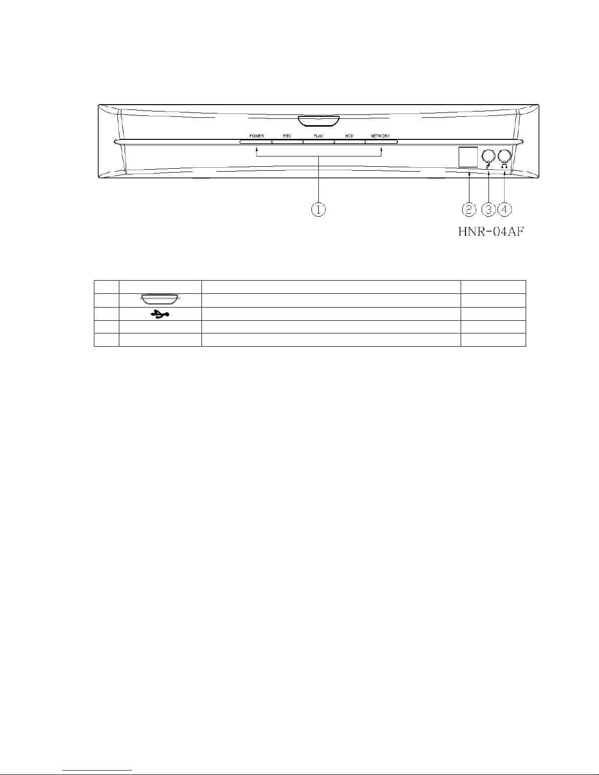
2.1 FRONT PANEL
NVR OPERATION
NO.
LABEL
OPERATION
PTZ
1
IR Sensor For Remote Control.
2
4321
76 8
10 11 12
22
USB Connector
3
MIC IN
Mic phone input(Phone Jack)
4 AUDIO OUT
3.5mm Audio output(Phone Jack)
9
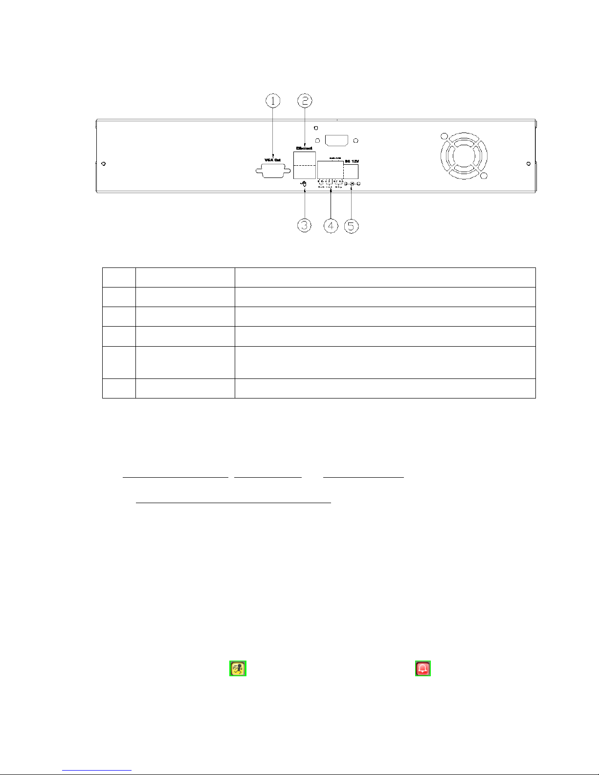
2.2 BACK PANEL
NO.
LABEL
OPERATION
1
VGA D-SUB OUT
Connect to CRT or LCD monitor。
2
ETHERNET
RJ-45 connector。
3
MOUSE
USB Mouse Connector
4
RS-485/ ALARM
IN/ RELAY OUT
2 pin RS-485/ 2 pin alarm input connector; 1 pin GND
connector/ 2 pin Relay connector, 1 pin COM connector
5
POWER
Power switcher: DC 12V/ 5A input
2.3 ALARM TRIGGER
There are three types of alarms that the system can be configured to handle. They are
Motion detection Alarm, External Alarm and Video Loss Alarm.
A. Motion detection Alarm and External Alarm:
When motion detection or External Alarm was triggered, there are 4 possible actions
will be taken.
a. Monitor will display corresponding full screen alarm channel, it will switch
automatic mode to manual mode if buttons pressing activity occurred in 5 seconds.
b. Relays can be activated by motion detection or external alarm when turning on.
c. External alarm will be recorded in the event list. Motion detection can be set to yes
or no.
d. On the top right of the channel which the alarm triggered, the icons pop up to
remind the user. stands for motion detection alarm. stands for external
alarm.
10
B. Video Loss Alarm:
The default setting of Video Loss alarm is enabled and cannot be changed. Although
buzzer action can be disabled, an ALM record will still be added to the Event List that
indicates the precise time of video loss. On the top right of the channel which the alarm
triggered, the icon pop up to remind the user.
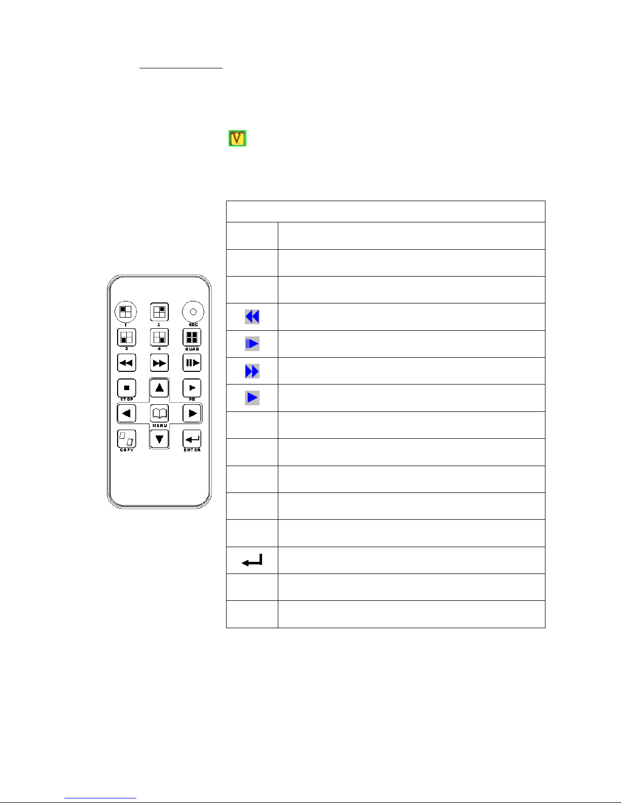
2.4 IR REMOTE CONTROL
ITEM
REC
Press REC to start recording and press twice to
stop.
1 - 4
Select channel 1-4 with full screen.
QUAD
Fast backward.
Picture by picture backward.
Picture by picture forward.
Fast Forward.
Play video forward.
COPY
Switch channel format.
▲
Move upward or increase the number.
►
Move rightward or increase the number.
▼
Move downward or decrease the number.
◄
Move leftward or decrease the number.
Enter selected items.
MENU
Enter or Exit Main Menu.
STOP
Stop the playback.
11
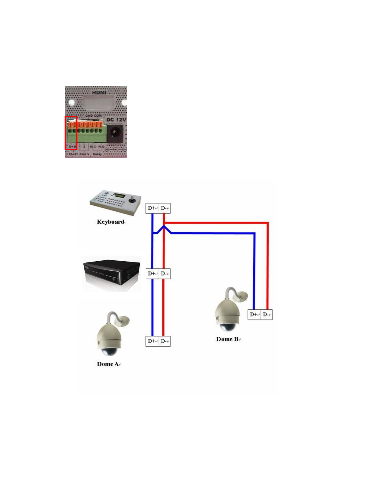
2.5 PTZ (PAN, TILT AND ZOOM) CAMERA
Following diagram for NVR connect between PTZ camera & joystick controller, for NVR to
control PTZ camera please make sure the CAMERA ID, BANDRATE (default at 9600 bps)
and RS-485 cable.
2 CORE
Under “Two Core” connection, controller can control speed dome without integrated protocol
into NVR. Moreover, one keyboard can connect MAX 256 units of speed dome.
12
3 SYSTEM SETUP
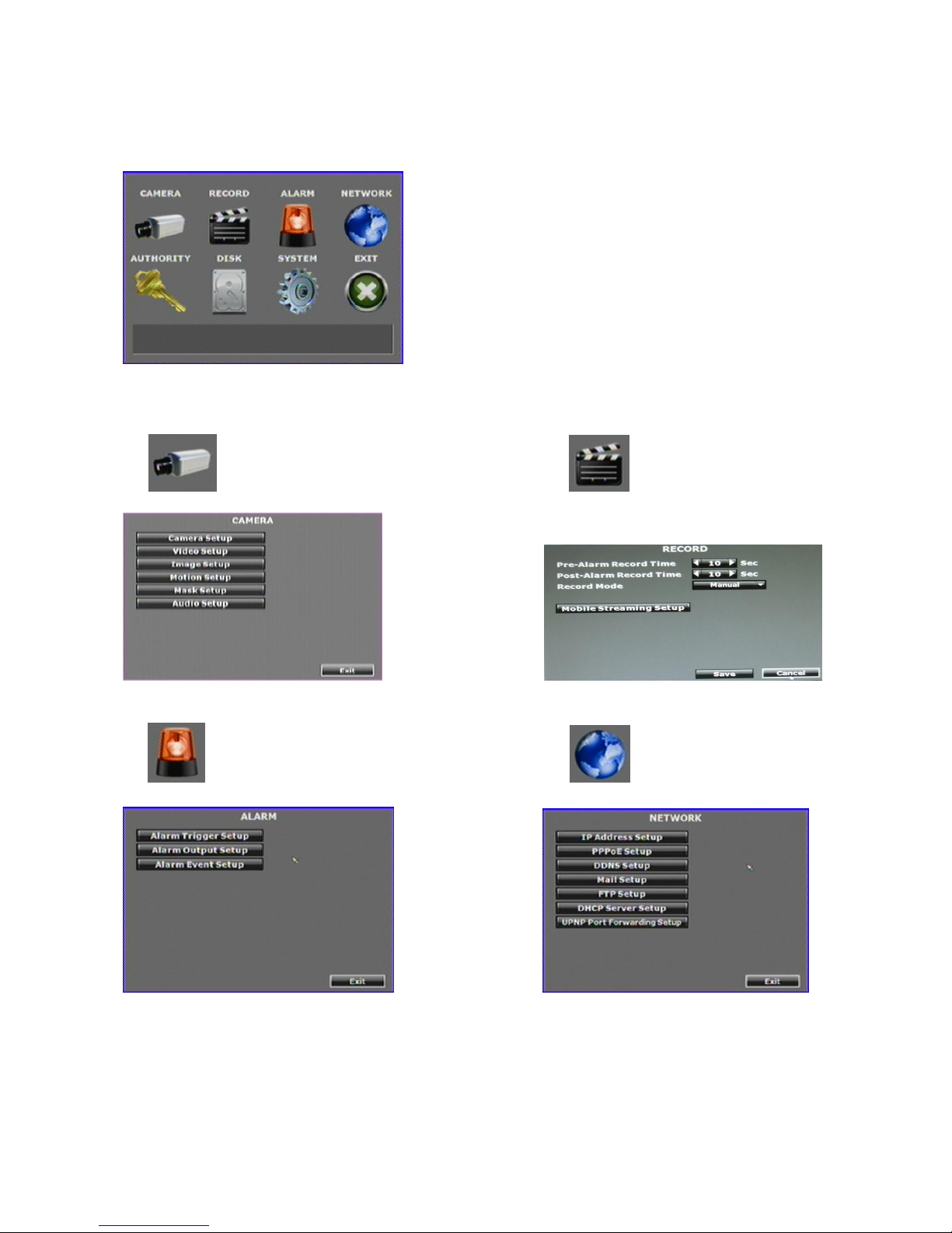
3.1 MENU SETUP INTERFACE(GUI)
A. CAMERA SETUP B. RECORD SETUP
C. ALARM SETUP D. NETWORK SETUP
13
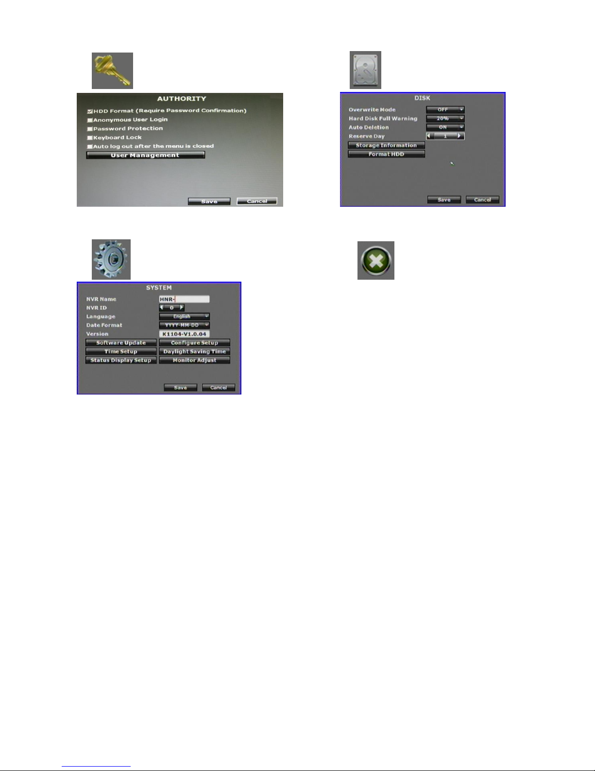
E. AUTHORITY SETUP F. DISK MANAGEMENT
G. SYSTEM SETUP H. EXIT
14
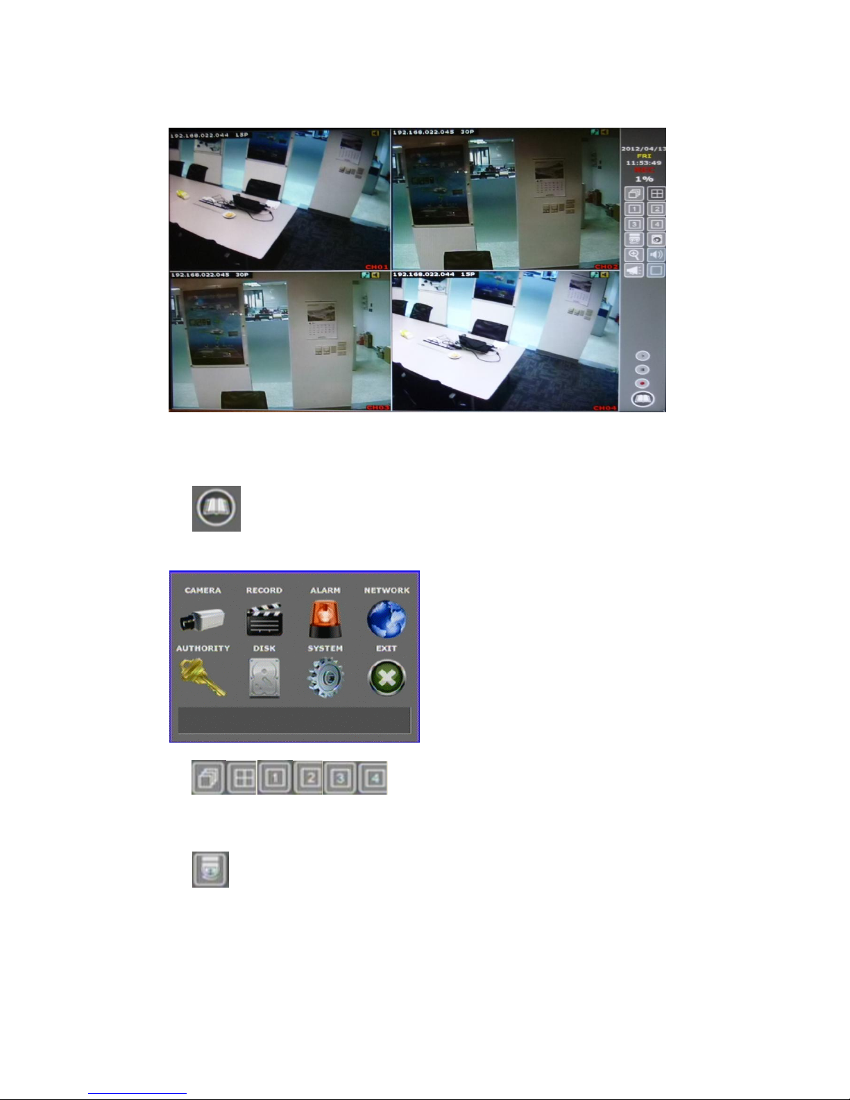
3.2 LIVE VIEWING AND POP-UP MENU
NOTE:The pop-up menu can be activated by moving the mouse cruise to the bottom
of the live viewing screen.
A. GUI MENU BAR
With live viewing mode, press this button to get into the GUI menu.
B. DISPLAY CONTROL
Within live-viewing or playback mode, use display control to switch the camera
channel.
C. PTZ CONTROLLER
Within live-viewing mode, Clicks this button to get into the PTZ setup menu. User can
right-click the button of the mouse to exit PTZ Setup.
NOTE: Only for the camera supported PTZ function.
PTZ CONTROL
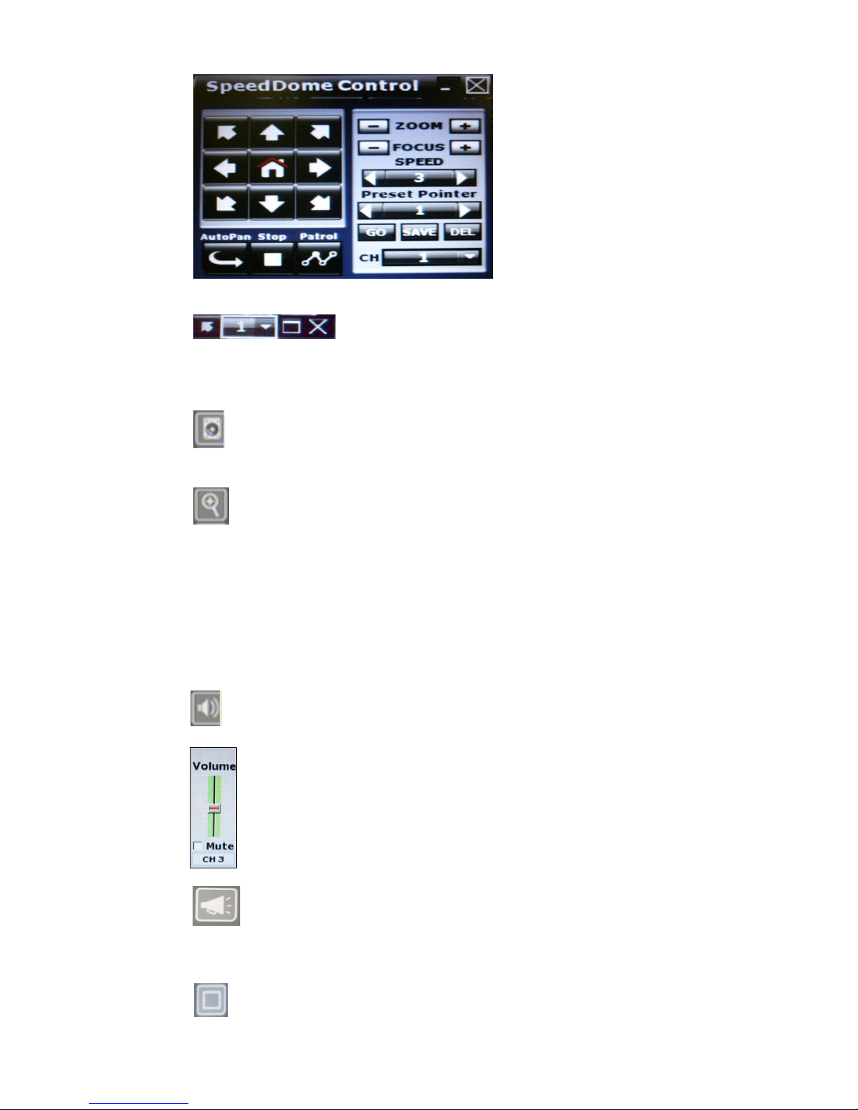
15
Press the minimization icon then the control panel becomes smaller:
Move the mouse and the arrow will follow the mouse and change direction. In this
mode user can click on the live view to control direction instead of the direction
key on control panel.
D. DISK INFORMATION
With live viewing mode, press this button to display disk information.
E. DIGITAL ZOOM
In the live full screen mode, left-click the button of the mouse to pull a range to zoom
in or zoom out the image. User can right-click the button of the mouse to disable this
function. (NOTE: Using the mouse to operate digital zoom can zoom in to max. 16
times.) Moreover, user can also use ZOOM key on the front panel to perform this
function. (First, click ZOOM Key and then click ▲▼◄► key to select zoom in or
zoom out position. Finally, click ENTER key to complete the setting. Moreover, click
ZOOM Key again can disable digital zoom function. Using the panel key to perform
zoom in function is fixed at 2 times.)
F. AUDIO CONTROL
Press this button, and the audio volume control board will pop up.
G. BOARDCASTING
Press the bottom to enable or disable the one way audio. Broadcasting can be applied
to multiple channels simultaneously.
H. FULL SCREEN

16
Press the bottom for full-screen mode.
I. RECORD AND PLAYBACK CONTROL
Same as front panel controller and remote controller.
J. SOUND INPUT/ SOUND OUTPUT / PTZ CONTROL
There are little icon on the right top of the live vide of every channel. Click to
enable the two ways audio. Click to enable the sound output. Click to
PTZ call out the control board. Note that if those functions are not support by the
camera linked, you will not see the corresponding icons.
The sound options do not affect the audio recorded into playback video. As long as the
audio setup is enabled, the playback video includes audio even the sound output here
is turned off.
17
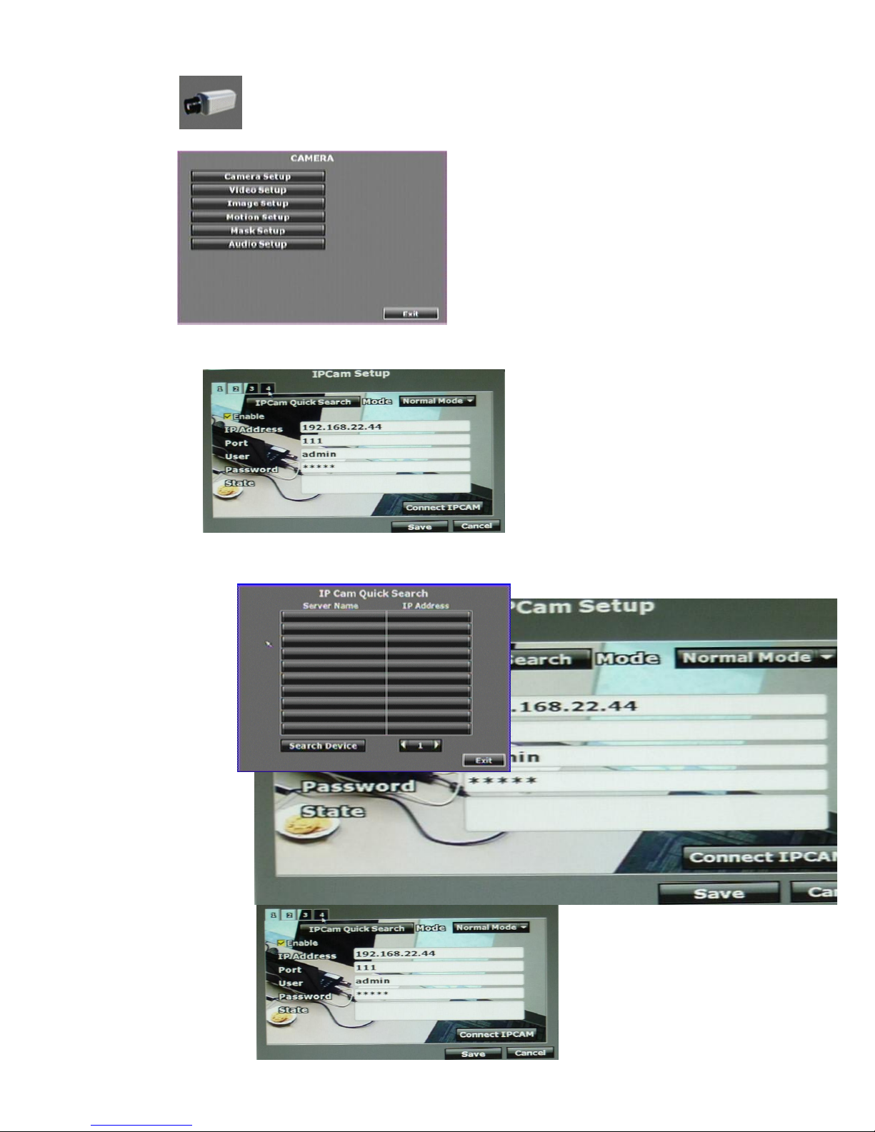
3.3 CAMERA SETUP
A. IPCam Setup
A-1. IPCam Quick Search
Press the “IPCam Quick Search” button and click “Search Device” button in the
following, NVR will search the IPCAM devices which IP address are setup as
the same domain as NVR IP address. Moreover, click the IPCam device which
from the list can import the device information to the channel automatically
without any manual key-in step.
a. Normal Mode
18
1. Enable: Choose “Normal Mode”
2. IP Address:Insert the IP address of the connecting device.
3. Port:Insert the port number of the connecting device. Default port: 80
4. User:Insert the user name of the connecting device.
5. Password:Insert the password of the connecting device.
6. State:After click the “connect IPCAM” button to test the IPCAM device,
the connection state will reveal among this column.
Note: To the camera connected via ONVIF protocol, the PTZ control function
is not supported.
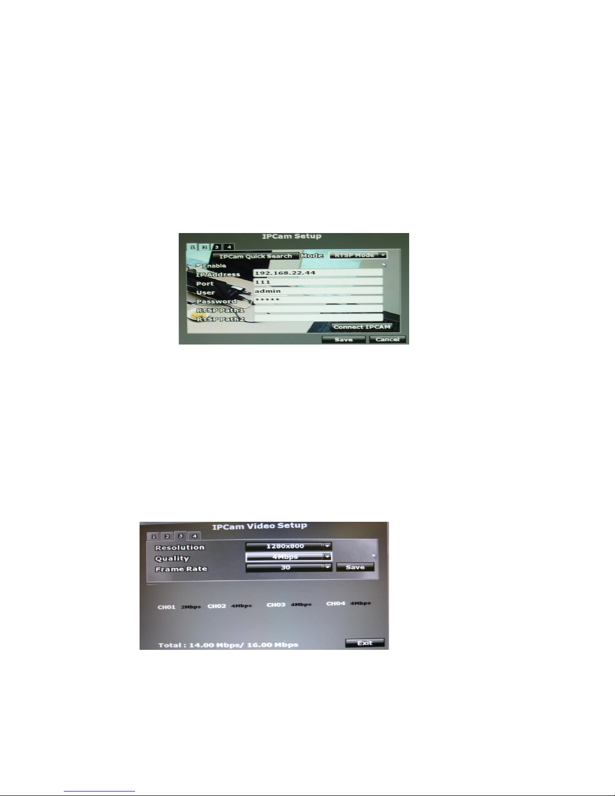
b. RSTP Mode
Under RTSP Mode, the NVR only support the IP address indication, the live
video, and video recording. Other functions like motion detection are not
supported.
1. Enable: Choose “RTSP Mode”
2. IP Address:Insert the IP address of the connecting device.
3. Port:Insert the port number of the connecting device. Please key in “554”
here.
4. User:Insert the user name of the connecting device.
5. Password:Insert the password of the connecting device.
6. RTSP Path:To link to the IP camera, check the RTSP Path settings of your
IP camera, and key in the corresponding value here.
A-2. Connect IPCAM:After insert the IPCAM related information, click this button
to test the connection circumstances.
B. IPCam Video Setup
B-1. Resolution
Click drop down list to change the resolution of connecting device.
B-2. Quality
Click drop down list to change the image quality.
For H.264 IPCam above 1 Megapixel, the resolution options support “4Mbps,

19
3Mbps, 2Mbps, 1.5Mbps, 1Mbps”.
For H.264 IPCam less than 1 Megapixel, the resolution options support” 2Mbps,
1.5Mbps, 1Mbps, 512Kbps, 256Kbps”
For MPEG IPCam, the resolution options support “Standard, Medium, Low”.
(The highest resolution option is “standard” due to the chip performance limits
of IPCam)
B-3. FrameRate
Click drop down list to change the frame rate of connecting device.
C. IPCam Image Setup
C-1. Display
Use the mouse to enable or disable the camera display on the screen or not.
C-2. Title
Use the mouse to setup the title of connecting IP device.
C-3. Switch Dwell
Press ◄ or ► to change auto switch second. The value is between 0~99 sec.
C-4. Contrast
Press ◄ or ► to change contrast level. The adjustment value is between 0~255
C-5. Brightness
Press ◄ or ► to change brightness level. The adjustment value is between
0~255
C-6. Hue
Press ◄ or ► to change hue level. The adjustment value is between 0~255
C-7. Saturation
Press ◄ or ► to change saturation level. The adjustment value is between
0~255
C-8. Sharpness
Press ◄ or ►/ mouse wheel to change sharpness level. The adjustment value is
between 0~15
D. Motion Setup
20
D-1. Relay Dwell
Press ◄ or ► to change the relay time or disable relay function.
D-2. Buzzer Dwell
Press ◄ or ► to change the buzzer time or disable buzzer function.
D-3. Area1 Sensitivity
Press ◄ or ► to change the sensitivity of setup motion area in Area1. Click
“Motion Area Setup” and drag a blue area for motion detection.
D-4. Area2 Sensitivity
Press ◄ or ► to change the sensitivity of setup motion area in Area2. Click
“Motion Area Setup” and drag a green area for motion detection.
D-5. Area3 Sensitivity
Press ◄ or ► to change the sensitivity of setup motion area in Area3. Click
“Motion Area Setup” and drag a red area for motion detection.
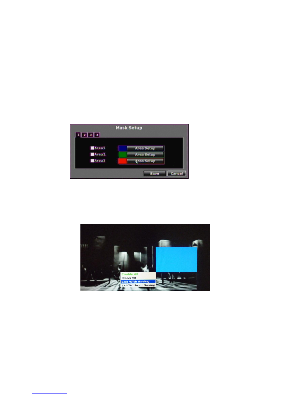
E. Mask Setup
The masked area will not show on the live video and video playback.
E-1. Area1
Tick the “Area1” box and click “Area Setup” to drag a blue area for masking.
E-2. Area2
Tick the “Area1” box and click “Area Setup” to drag a green area for masking.
E-3. Area3
Tick the “Area1” box and click “Area Setup” to drag a red area for masking.
F. Audio Setup
The channel ticked means the sound from camera will be recorded into the playback
video. Vise versa. No sound will be recorded in the playback video of the channel
which is not ticked.

21
22
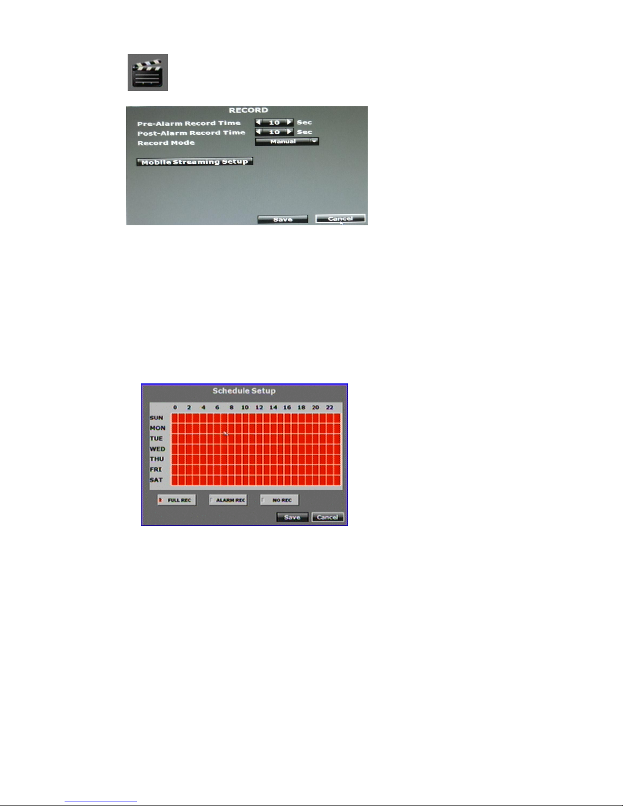
3.4 RECORD SETUP
A. Pre-Alarm Record Time
Press ◄ or ► to switch the recording time of pre-alarm. The adjusting value is from
5~99 sec.
B. Post-Alarm Record Time
Press ◄ or ► to switch the recording time of post-alarm. The adjusting value is from
5~99 sec.
C. Record Mode
Use the drop down list to switch the recording mode. There are manual, schedule and
alarm trigger three varieties of mode.
Schedule Setup
Click the “Schedule Setup” button to set the schedule recording time.
D. Mobile Streaming Setup
Press on to record the streaming for mobile viewing
 Loading...